EP0157630B1 - Force motor - Google Patents
Force motor Download PDFInfo
- Publication number
- EP0157630B1 EP0157630B1 EP19850302306 EP85302306A EP0157630B1 EP 0157630 B1 EP0157630 B1 EP 0157630B1 EP 19850302306 EP19850302306 EP 19850302306 EP 85302306 A EP85302306 A EP 85302306A EP 0157630 B1 EP0157630 B1 EP 0157630B1
- Authority
- EP
- European Patent Office
- Prior art keywords
- armature
- assembly
- magnetic
- spring
- force
- Prior art date
- Legal status (The legal status is an assumption and is not a legal conclusion. Google has not performed a legal analysis and makes no representation as to the accuracy of the status listed.)
- Expired - Lifetime
Links
Images

Classifications
-
- H—ELECTRICITY
- H01—ELECTRIC ELEMENTS
- H01F—MAGNETS; INDUCTANCES; TRANSFORMERS; SELECTION OF MATERIALS FOR THEIR MAGNETIC PROPERTIES
- H01F7/00—Magnets
- H01F7/06—Electromagnets; Actuators including electromagnets
- H01F7/08—Electromagnets; Actuators including electromagnets with armatures
- H01F7/16—Rectilinearly-movable armatures
- H01F7/1607—Armatures entering the winding
- H01F7/1615—Armatures or stationary parts of magnetic circuit having permanent magnet
-
- H—ELECTRICITY
- H01—ELECTRIC ELEMENTS
- H01F—MAGNETS; INDUCTANCES; TRANSFORMERS; SELECTION OF MATERIALS FOR THEIR MAGNETIC PROPERTIES
- H01F7/00—Magnets
- H01F7/06—Electromagnets; Actuators including electromagnets
- H01F7/08—Electromagnets; Actuators including electromagnets with armatures
- H01F7/121—Guiding or setting position of armatures, e.g. retaining armatures in their end position
- H01F7/122—Guiding or setting position of armatures, e.g. retaining armatures in their end position by permanent magnets
-
- Y—GENERAL TAGGING OF NEW TECHNOLOGICAL DEVELOPMENTS; GENERAL TAGGING OF CROSS-SECTIONAL TECHNOLOGIES SPANNING OVER SEVERAL SECTIONS OF THE IPC; TECHNICAL SUBJECTS COVERED BY FORMER USPC CROSS-REFERENCE ART COLLECTIONS [XRACs] AND DIGESTS
- Y10—TECHNICAL SUBJECTS COVERED BY FORMER USPC
- Y10T—TECHNICAL SUBJECTS COVERED BY FORMER US CLASSIFICATION
- Y10T137/00—Fluid handling
- Y10T137/8593—Systems
- Y10T137/86493—Multi-way valve unit
- Y10T137/86574—Supply and exhaust
- Y10T137/86622—Motor-operated
Description
- The invention relates to force motors as used in fluid power systems and, more particularly, to force motors wherein electro-magnetic coils are used to bias the field strength of a permanent magnet.
- Controls for hydraulic power systems have had a long history of development. Early control systems were primarily mechanical linkages. These systems were reliable, but tended to be heavy, bulky and somewhat limited in capabilities. Also, as mechanical control systems grew in size and complexity they became increasingly costly to manufacture and maintain.
- As an alternative to mechanical systems, electrical control systems became increasingly popular, particularly in aviation and related fields. Electrical control systems generally could be made smaller, lighter and more versatile than mechanical systems. However, electrical control systems had other disadvantages. For example, the quiescent leakage of electro-hydraulic valves was relatively high.
- Consequently, such systems required more power, generated more heat, and were generally more costly. Applications requiring redundancy in the control system, such as aviation applications, merely compounded these factors with a multiplicity of components in complex redundancy management systems.
- Accordingly, it was recognized in the prior art that a mechanism that directly controlled hydraulic valves would be more efficient in terms of quiescent leakage and thus have many advantages over hydraulic control systems known in the prior art. Moreover, such use of direct drive valves would increase reliability and decrease bulk and weight of the hydraulic system. In addition, it was also recognized that direct drive valves would require only limited failure monitoring for the control system, resulting in a correlative improvement in redundancy management.
- Early direct drive valves employed force motors in which a magnetic assembly comprising electrical coils was used to control the position of an armature. Subsequently the electrical coils were replaced by a permanent magnet in combination with several smaller electrical coils that were used to bias the field of the permanent magnet. It was found that this provided a magnetic assembly that was lighter and had lower power requirements than prior magnetic assemblies having no permanent magnets.
- Previously, direct drive valves were developed having much-improved quiescent leakage characteristics typically in the range of 10% to 1%. One example is shown in a paper entitled "Application and Use of Rare Earth Magnets" by M. F. Marx, prepared for SAE Aerospace Control and Guidance Systems Committee, meeting No. 41, Palo Alto, California. However, several disadvantages remained in force motors known to the prior art. For example, some force motors had no mechanism for isolating the electrical coils of the magnetic assembly from the fluid of the hydraulic system. This exposure to hydraulic fluid made the magnetic assembly subject to premature failure. Other persistent problems with force motors have included a requirement for relatively high threshold command signals to initiate movement of the armature from a stationary position, as well as hysteresis in the armature movement relative to control current. These problems adversely effected the performance characteristics of the force motor, particularly sensitivity and stability.
- Patent specification DE-A-20 24 024 discloses a double stroke magnet comprising an armature and magnetic coils connectable with a hydraulic valve. The armature is axially movable in a housing and is supported at both ends by respective flat springs comprising annular shaped discs with a single tongue member projecting radially inwards and provided with a central opening arranged to permit mounting on a central shaft of the armature. The tongue member of each spring is bent slightly out of the annular disc plane to provide a pre-tensioning on the armature.
- Patent specification DE-A-14 14 815 discloses a somewhat similar arrangement but wherein a casing contains a permanent magnet having electrical coils on each side thereof. Energizing voltages may be applied to the coils to move the armature from a centrally located position in the casing, such location being maintained by a pair of coil springs, one disposed at each end of the armature and acting on housing end flanges.
- Patent specification DE-A-29 19 667 discloses springs cut from discs and comprising a plurality of radial arms each widened at its outer end to give a generally triangular shaped portion.
- According to the invention there is provided a force motor comprising:
- a casing;
- first and second pole pieces disposed at opposite ends of the casing;
- a magnetic assembly located within the casing and between the pole pieces, the magnetic assembly including a permanent magnet and one or more electrical coils;
- an armature that is movable between the pole pieces in response to an input signal to the magnetic assembly; and
- a spring assembly including first and second cantilevered springs in complementary arrangement with the deflection of the first spring being of opposite sense from the deflection of the second spring, the spring assembly being connected to the armature and opposing movement of the armature from a reference position and the opposing force of the spring assembly when the armature is out of the reference position being greater than the force of the permanent magnet of the magnetic assembly with no input current to the coils, characterised in that each of the cantilevered springs is formed as a disc with an aperture at the centre forming an inner edge and with slots extending from the aperture to form a plurality of triangularly shaped petals circumjacently arranged along the inner edge.
- The connection of the springs to the armature can be by contact between a mechanical extension of the armature and a respective face of each spring adjacent an inner edge thereof.
- Preferably, the armature is concentrically maintained in the magnetic assembly by a plurality of balls that contact the surfaces of both the armature and a tube assembly that is sleeved inside the magnetic assembly.
- The invention is diagrammatically illustrated by way of example with reference to the accompanying drawings, in which:
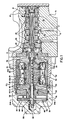
- Figure 1 is a cross-sectional view of a direct drive valve showing a force motor according to the invention;
- Figure 2 is a cross-section of the direct drive valve of Figure 1 taken on line 2-2 and showing a cantilevered spring;
- Figure 3 is an enlarged partial cross-section of the direct drive valve of Figure 1 showing a portion of the spring assembly;
- Figure 4 is an enlarged partial cross-section of the direct drive valve of Figure 1 showing the balls and retainers that support the armature in the tube assembly;
- Figure 5 is a perspective view of the retainer of the ball and retainer assembly shown in Figures 1 and 4; and
- Figure 6 shows a perspective view of an alternative embodiment of the retainer shown in Figure 5.
- Referring to the drawings, a force motor 10 controls the position of a valve 12 through a
direct linkage 14. - The valve 12 includes a
manifold 16 that is provided with appropriate porting for connection to a hydraulic system. Avalve sleeve 18 that includesmetering orifices 19 is fitted within an internal bore of themanifold 16. Avalve slide 20 is slidably maintained in thesleeve 18. Thevalve slide 20 is provided with a plurality oflands 24 and grooves 22 that, in conjunction with themetering orifices 19, control the fluid flow to the sleeve ports in accordance with the position of thevalve slide 20. - The force motor 10 is connected to the
valve slide 20 through thelinkage 14 that includes a self-aligningjoint 26. Amagnetic pin 28 is provided adjacent the self-aligningjoint 26 to collect metallic particles in the fluid. - The force motor 10 includes a
casing 30 concentrically arranged about a magnetic assembly 32. The magnetic assembly 32 includes apermanent magnet 34 and electro-magnetic coils coils annular frames 40 and 42. The coils are electrically connected in series or in parallel with the number of coil turns being determined, in part, by the strength of thepermanent magnet 34. - Also included in the force motor 10 are
pole pieces casing 30 and the magnetic assembly 32. Atube assembly 47 is sleeved within the magnetic assembly 32 and between thepole pieces tube assembly 47 includes a magnetic central band 47a that engages longitudinally aligned, non-magentic outer bands 47b and 47c on opposite ends thereof. An armature 48 is located adjacent to the magnetic assembly 32 within thetube assembly 47 and between thepole pieces pole pieces - A
rod 50 extends longitudinally through the armature 48 and is secured to the end faces of the armature 48 byretainers rod 50 is connected at one end to the self-aligningjoint 26 of thedirect linkage 14. At the opposite end therod 50 extends from the armature 48 into a chamber 56 that is defined by anannular spacer 58 in co-operation with acover 60. Thecover 60 engages one end of ahousing 61 that supports thecasing 30 and thepole pieces passageways 51 extend longitudinally through the armature 48 such that the chamber 56 is in fluid communication with the valve 12 by a flow path through thepassageways 51 and around theretainers direct linkage 14. - An o-ring 62a is provided between the outer band 47b and the
pole piece 44 and an o-ring 62b is provided between the outer band 47c and thepole piece 46. The o-rings 62a and 62b form a seal between thetube assembly 47 and thepole pieces tube assembly 47 and thepole pieces - In the chamber 56, the
rod 50 is connected to spacers 64 and 66 which co-operate with therod 50 to form a mechanical extension of the armature 48 that mechanically couples the armature to aspring assembly 62. Thespring assembly 62 includes cantilevered springs 68 and 70 which are maintained in spaced-apart, parallel relationship by anannular spacer 76. As particularly shown in Figure 2, thesprings petals 72 that are circumjacently arranged along aninner edge 74. Thespring assembly 62 is secured in cantilevered fashion against ashoulder 78 of thecover 60 by compression between theshoulder 78 and theannular spacer 58. As specifically used herein, thesprings inner edge 74. - As best shown in Figure 3, the faces of the
spacers springs annular flanges annular flanges springs inner edge 74. The contact surfaces of theannular flanges annular flanges springs flanges flanges springs flanges - As particularly shown in Figures 4 and 5, a plurality of
balls 84 supports the armature 48 concentrically within the magnet assembly 32 and thetube assembly 47 in a longitudinally movable manner. In the preferred embodiment, the armature 48 is provided with annular grooves 86 and 88 having base surfaces 90 and 91. Theballs 84 contact the base surfaces 90 and 91 and thetube assembly 47 to maintain the armature 48 in a fixed radial position within thetube assembly 47 such that it is substantially aligned with the longitudinal central axis of the magnetic assembly 32. - The
balls 84 are circumferentially maintained in regularly spaced relationship in theannular grooves 84 and 88 byretainers retainers retainers balls 84 located in the respective holes of the retainer protrude radially through the sides thereof and contact thetube assembly 47 and the base surfaces 90 and 91 of the armature 48. The width of theretainers retainers pole pieces retainers - Figure 6 shows an alternative embodiment of a retainer for the
balls 84. In that embodiment, a retainer 94 is provided with elongate holes corresponding to therespective balls 84. In contrast to theretainer 92 of Figure 5, the retainer 94 is secured to the armature 48 and does not move freely with respect thereto. Instead, the major axes of the elongate holes are generally aligned with the longitudinal movement of the armature 48 and, as the armature 48 moves between thepole pieces balls 84 traverse the elongate holes. The width of the retainer 94 and the dimension of the elongate holes along their major axis is sized with respect to the stroke of the armature 48. Thus, as the armature 48 moves between thepole pieces balls 84 move freely along the elongate holes. - In the operation of the preferred embodiment, the armature 48 is connected through the
direct linkage 14 to thevalve slide 20. Thus, the movement of the armature 48 results in a corresponding movement of thevalve slide 20 to determine the flow of fluid through the valve 12. The force motor 10 controls the position of the armature 48 by balancing the magnetic force exerted on the armature 48 by the magnetic assembly 32 against the opposing spring force of thespring assembly 62. - The magnetic assembly 32 provides a magnetic field having a permanent field component and a variable field component. The non-magnetic outer bands 47b and 47c of the
tube assembly 47 co-operate with the central band 47a to channel the magnetic field through the end of the armature 48 and thepole pieces permanent magnet 34 and the variable field component is developed by thecoils coils - The spring force of the
spring assembly 62 is greater than the magnetic forces between the armature 48 and thepole pieces permanent magnet 34 alone. Thus, with no input current to thecoils spring assembly 62 maintains the armature 48 at a reference position as shown in Figure 1. However, when input current is supplied to thecoils pole pieces spring assembly 62 at the reference position. The armature 48 then moves toward thepole piece coils - As the armature 48 moves from the reference position, the spring force of the
spring assembly 62 increases substantially in proportion to the mechanical displacement of thespring pole pieces - As specifically shown in Figure 2, to provide redundancy in the
spring assembly 62, the cantilevered springs 68 and 70 each include the plurality of triangularly shapedpetals 72. Thepetals 72 are of an angular size such that the loss of a specified number of petals does not substantially affect the spring force of thespring assembly 62 with respect to displacement of thesprings - To limit the required thickness of the
springs spring assembly 62 in view of the petal structure of thesprings springs respective spacer spring 70 operates against thespacer 66 to oppose this movement and thespring 68 moves out of contact withspacer 64. Conversely, as the armature 48 moves from the reference position in a direction toward the valve 12, thespring 70 moves away from thespacer 66, but thespring 68 operates against thespacer 64 to oppose the armature movement. - The use of the two
springs spacers spacers rod 50. Thus the mechanical extension between the armature 48 and thespring assembly 62 provides for adjustment to compensate for variations within tolerances, in thespring assembly 62 and elsewhere in the force motor 10. - The force motor of the invention can have low threshold friction and low mechanical hysteresis. Fluid at the end of the armature 48 that is adjacent the
linkage 14 communicates through thepassageways 51 with the opposite end of the armature 48, the chamber 56, and thespring assembly 62. Thus, no dynamic seals are required between the armature 48 and thetube assembly 47, eliminating the frictional effects of any dynamic fluid seal on the armature. - As specifically shown in the cross-sectional view of Figure 3, further to limit threshoid friction in the force motor, the
flanges spacers flanges springs flanges spacers springs spacers spacers springs - The
balls 84 are circumferentially maintained in theretainers balls 84 maintain the armature 48 concentrically within thetubular assembly 47 and concentrically within the magnetic assembly 32. Theballs 84, which contact both thetubular assembly 47 and the armature 48, operate as free- rolling guides for the armature. Thus theballs 84 also operate in a manner that limits frictional effects on the armature 48 and produces more linear movement and greater sensitivity of the force motor 10 in response to input current. - Attention is directed co-pending applications 85302208.3 published under number EP-A-157632 and 85 302 307. 5 published under number EP-A-157 651 which have substantially the same disclosure as this application but claims of different scope.
Claims (6)
characterised in that each of the cantilevered springs (68,70) is formed as a disc with an aperture at the centre forming an inner edge (74) and with slots extending from the aperture to form a plurality of triangularly shaped petals (72) circumjacently arranged along the inner edge (74).
Applications Claiming Priority (2)
| Application Number | Priority Date | Filing Date | Title |
|---|---|---|---|
| US06/596,489 US4525695A (en) | 1984-04-04 | 1984-04-04 | Force motor with ball mounted armature |
| US596489 | 1984-04-04 |
Publications (3)
| Publication Number | Publication Date |
|---|---|
| EP0157630A2 EP0157630A2 (en) | 1985-10-09 |
| EP0157630A3 EP0157630A3 (en) | 1986-09-17 |
| EP0157630B1 true EP0157630B1 (en) | 1990-06-27 |
Family
ID=24387487
Family Applications (1)
| Application Number | Title | Priority Date | Filing Date |
|---|---|---|---|
| EP19850302306 Expired - Lifetime EP0157630B1 (en) | 1984-04-04 | 1985-04-02 | Force motor |
Country Status (4)
| Country | Link |
|---|---|
| US (1) | US4525695A (en) |
| EP (1) | EP0157630B1 (en) |
| JP (1) | JPH0755039B2 (en) |
| DE (1) | DE3578478D1 (en) |
Families Citing this family (31)
| Publication number | Priority date | Publication date | Assignee | Title |
|---|---|---|---|---|
| US4651118A (en) * | 1984-11-07 | 1987-03-17 | Zeuner Kenneth W | Proportional solenoid |
| DE3507441A1 (en) * | 1985-03-02 | 1986-09-04 | Robert Bosch Gmbh, 7000 Stuttgart | ELECTROMAGNETICALLY ACTUABLE FUEL INJECTION VALVE AND METHOD FOR THE PRODUCTION THEREOF |
| DE3527423A1 (en) * | 1985-07-31 | 1987-02-12 | Bso Steuerungstechnik Gmbh | ELECTROMAGNET |
| US4635683A (en) * | 1985-10-03 | 1987-01-13 | Ford Motor Company | Variable force solenoid |
| US4835503A (en) * | 1986-03-20 | 1989-05-30 | South Bend Controls, Inc. | Linear proportional solenoid |
| US4787412A (en) * | 1986-12-24 | 1988-11-29 | Hagglunds Denison | Cartridge valve |
| US5257639A (en) * | 1988-12-23 | 1993-11-02 | Dresser Industries, Inc. | Electropneumatic positioner |
| US4926896A (en) * | 1988-12-23 | 1990-05-22 | Dresser Industries, Inc. | Sensitive electrical to mechanical transducer |
| US5159949A (en) * | 1988-12-23 | 1992-11-03 | Dresser Industries, Inc. | Electropneumatic positioner |
| DE4214284A1 (en) * | 1992-04-30 | 1993-11-04 | Schneider Co Optische Werke | ELECTROMAGNETIC LINEAR MOTOR |
| US5249603A (en) * | 1992-05-19 | 1993-10-05 | Caterpillar Inc. | Proportional electro-hydraulic pressure control device |
| GB9218610D0 (en) * | 1992-09-03 | 1992-10-21 | Electro Hydraulic Technology L | Linear motor valve |
| US5252939A (en) * | 1992-09-25 | 1993-10-12 | Parker Hannifin Corporation | Low friction solenoid actuator and valve |
| US5355108A (en) * | 1992-10-05 | 1994-10-11 | Aura Systems, Inc. | Electromagnetically actuated compressor valve |
| EP0664861B1 (en) * | 1992-10-15 | 1998-01-14 | Parker Hannifin Corporation | Expansion valve for air conditioning system with proportional solenoid |
| DE19531444A1 (en) * | 1995-08-26 | 1997-02-27 | Hydraulik Ring Gmbh | Actuating unit for an adjustment device, preferably for a valve lift adjustment device of motor vehicles |
| JP2004092741A (en) * | 2002-08-30 | 2004-03-25 | Honda Motor Co Ltd | Electromagnetic brake |
| EP1420321A3 (en) * | 2002-11-15 | 2005-04-20 | HydraForce, Inc. | Dual proportional pressure reducing valve |
| US7007925B2 (en) * | 2004-08-05 | 2006-03-07 | Husco International, Inc. | Electrohydraulic valve having an armature with a rolling bearing |
| US8056576B2 (en) | 2007-08-27 | 2011-11-15 | Husco Automotive Holdings Llc | Dual setpoint pressure controlled hydraulic valve |
| US8186378B2 (en) * | 2008-04-15 | 2012-05-29 | Husco Automotive Holdings, LLC | Filter band for an electrohydraulic valve |
| US7992839B2 (en) * | 2008-04-15 | 2011-08-09 | Husco Automotive Holdings Llc | Electrohydraulic valve having a solenoid actuator plunger with an armature and a bushing |
| US8006719B2 (en) * | 2008-04-15 | 2011-08-30 | Husco Automotive Holdings Llc | Electrohydraulic valve having a solenoid actuator plunger with an armature and a bearing |
| DE102010039711A1 (en) * | 2010-08-24 | 2012-03-01 | Bucher Hydraulics Gmbh | detent device |
| EP2872958B1 (en) | 2012-07-11 | 2018-05-02 | Flextronics AP, LLC | Direct acting solenoid actuator |
| US9322416B2 (en) | 2013-03-11 | 2016-04-26 | Hydraforce, Inc. | Multi-functional proportional control valve for hydraulic suspension system for vehicle |
| US9704636B2 (en) | 2015-02-17 | 2017-07-11 | Enfield Technologies, Llc | Solenoid apparatus |
| CN204886625U (en) * | 2015-06-15 | 2015-12-16 | 瑞声光电科技(常州)有限公司 | Linear vibration motor |
| JP6991987B2 (en) * | 2016-03-07 | 2022-01-13 | フスコ オートモーティブ ホールディングス エル・エル・シー | Electromagnetic actuator with integrated magnetic pole piece |
| US10578226B2 (en) * | 2016-12-22 | 2020-03-03 | Mac Valves, Inc. | Valve with two-piece adjustable can with integral pole piece |
| US11459220B2 (en) * | 2017-11-30 | 2022-10-04 | Danfoss Power Solution II Technology A/S | Hydraulic system with load sense and methods thereof |
Family Cites Families (14)
| Publication number | Priority date | Publication date | Assignee | Title |
|---|---|---|---|---|
| US1293052A (en) * | 1914-08-01 | 1919-02-04 | John L Dinsmoor | Electromagnetic mechanism. |
| US3022450A (en) * | 1958-09-15 | 1962-02-20 | Bendix Corp | Dual position latching solenoid |
| DE1414815A1 (en) * | 1960-10-24 | 1968-10-03 | List Dipl Ing Heinrich | Polarized double stroke magnet |
| US3119940A (en) * | 1961-05-16 | 1964-01-28 | Sperry Rand Corp | Magnetomotive actuators of the rectilinear output type |
| DE2024024A1 (en) * | 1970-05-15 | 1971-12-02 | Elektroteile Gmbh | DC plunger magnet |
| JPS4883356U (en) * | 1972-01-14 | 1973-10-11 | ||
| GB1578021A (en) * | 1976-05-01 | 1980-10-29 | Expert Ind Controls Ltd | Solenoid devices |
| GB2014795B (en) * | 1978-02-20 | 1982-06-16 | Jidosha Kiki Co | Electro-mechanical converters and control apparatus for power steering units utilizing the same |
| DE2823257A1 (en) * | 1978-05-27 | 1979-11-29 | Bosch Gmbh Robert | MAGNETIC VALVE |
| DD136814A1 (en) * | 1978-06-30 | 1979-08-01 | Walter Mandel | SPRING ELEMENT FOR DIVING ANCHOR MAGNETS |
| JPS58632A (en) * | 1981-06-23 | 1983-01-05 | Atsugi Motor Parts Co Ltd | Plate spring |
| JPS5889059A (en) * | 1981-11-16 | 1983-05-27 | ム−グ・インコ−ポレ−テツド | Electromechanical actuator |
| JPS58121326A (en) * | 1982-01-08 | 1983-07-19 | ル−ク・ラメレン・ウント・クツプルングスバウ・ゲゼルシヤフト・ミツト・ベシユレンクテル・ハフツング | Counter-sunk spring used for unit such as friction clutch |
| US4463332A (en) * | 1983-02-23 | 1984-07-31 | South Bend Controls, Inc. | Adjustable, rectilinear motion proportional solenoid |
-
1984
- 1984-04-04 US US06/596,489 patent/US4525695A/en not_active Expired - Lifetime
-
1985
- 1985-04-02 DE DE8585302306T patent/DE3578478D1/en not_active Expired - Lifetime
- 1985-04-02 EP EP19850302306 patent/EP0157630B1/en not_active Expired - Lifetime
- 1985-04-04 JP JP7184685A patent/JPH0755039B2/en not_active Expired - Lifetime
Also Published As
| Publication number | Publication date |
|---|---|
| US4525695A (en) | 1985-06-25 |
| EP0157630A2 (en) | 1985-10-09 |
| EP0157630A3 (en) | 1986-09-17 |
| JPS60229661A (en) | 1985-11-15 |
| DE3578478D1 (en) | 1990-08-02 |
| JPH0755039B2 (en) | 1995-06-07 |
Similar Documents
| Publication | Publication Date | Title |
|---|---|---|
| EP0157630B1 (en) | Force motor | |
| US5559378A (en) | Three-pole electromagnetic actuator for pneumatic distributing devices | |
| EP0157632B1 (en) | Force motor | |
| US5249603A (en) | Proportional electro-hydraulic pressure control device | |
| US4378031A (en) | Electrohydraulic servovalve | |
| US6422533B1 (en) | High force solenoid valve and method of improved solenoid valve performance | |
| US7455075B2 (en) | Servo valve with miniature embedded force motor with stiffened armature | |
| EP0157631B1 (en) | Force motor | |
| EP0740096A2 (en) | Valve actuator | |
| KR950002534B1 (en) | Solenoid vlave | |
| CA2441997A1 (en) | Actuator that functions by means of a movable coil arrangement | |
| JP7191297B2 (en) | servo valve | |
| CA1192249A (en) | Electro-magnet equipped with a moving system including a permanent magnet and designed for monostable operation | |
| EP0218430B1 (en) | Magnetic actuator | |
| EP0181056B1 (en) | Proportional solenoid | |
| US20180062491A1 (en) | Interstructural and Inertial Actuator | |
| US5012144A (en) | Linear direct drive motor | |
| US4286767A (en) | Solenoid actuated valve device | |
| US5341054A (en) | Low mass electromagnetic actuator | |
| US4473751A (en) | Non-conventional reciprocating hydraulic-electric power source | |
| CA1129470A (en) | Multi-stage solenoid actuator for extended stroke | |
| US5264813A (en) | Force motor having temperature compensation characteristics | |
| US3223104A (en) | Electro-hydraulic servo valve | |
| US4464978A (en) | Servovalve apparatus | |
| US4578604A (en) | Solenoid actuators |
Legal Events
| Date | Code | Title | Description |
|---|---|---|---|
| PUAI | Public reference made under article 153(3) epc to a published international application that has entered the european phase |
Free format text: ORIGINAL CODE: 0009012 |
|
| AK | Designated contracting states |
Designated state(s): DE FR GB IT |
|
| RAP1 | Party data changed (applicant data changed or rights of an application transferred) |
Owner name: PARKER HANNIFIN CORPORATION |
|
| PUAL | Search report despatched |
Free format text: ORIGINAL CODE: 0009013 |
|
| AK | Designated contracting states |
Kind code of ref document: A3 Designated state(s): DE FR GB IT |
|
| RHK1 | Main classification (correction) |
Ipc: H01F 7/16 |
|
| 17P | Request for examination filed |
Effective date: 19870202 |
|
| 17Q | First examination report despatched |
Effective date: 19880504 |
|
| ITF | It: translation for a ep patent filed |
Owner name: STUDIO D'ORIO |
|
| GRAA | (expected) grant |
Free format text: ORIGINAL CODE: 0009210 |
|
| AK | Designated contracting states |
Kind code of ref document: B1 Designated state(s): DE FR GB IT |
|
| REF | Corresponds to: |
Ref document number: 3578478 Country of ref document: DE Date of ref document: 19900802 |
|
| ET | Fr: translation filed | ||
| PLBE | No opposition filed within time limit |
Free format text: ORIGINAL CODE: 0009261 |
|
| STAA | Information on the status of an ep patent application or granted ep patent |
Free format text: STATUS: NO OPPOSITION FILED WITHIN TIME LIMIT |
|
| 26N | No opposition filed | ||
| ITTA | It: last paid annual fee | ||
| REG | Reference to a national code |
Ref country code: GB Ref legal event code: IF02 |
|
| PGFP | Annual fee paid to national office [announced via postgrant information from national office to epo] |
Ref country code: FR Payment date: 20030311 Year of fee payment: 20 |
|
| PGFP | Annual fee paid to national office [announced via postgrant information from national office to epo] |
Ref country code: GB Payment date: 20040316 Year of fee payment: 20 |
|
| PGFP | Annual fee paid to national office [announced via postgrant information from national office to epo] |
Ref country code: DE Payment date: 20040330 Year of fee payment: 20 |
|
| PG25 | Lapsed in a contracting state [announced via postgrant information from national office to epo] |
Ref country code: GB Free format text: LAPSE BECAUSE OF EXPIRATION OF PROTECTION Effective date: 20050401 |
|
| REG | Reference to a national code |
Ref country code: GB Ref legal event code: PE20 |