EP0157575B1 - Method for reduction in width of slabs by pressing and press for the same - Google Patents
Method for reduction in width of slabs by pressing and press for the same Download PDFInfo
- Publication number
- EP0157575B1 EP0157575B1 EP85302071A EP85302071A EP0157575B1 EP 0157575 B1 EP0157575 B1 EP 0157575B1 EP 85302071 A EP85302071 A EP 85302071A EP 85302071 A EP85302071 A EP 85302071A EP 0157575 B1 EP0157575 B1 EP 0157575B1
- Authority
- EP
- European Patent Office
- Prior art keywords
- slab
- anvils
- width
- pressing
- slabs
- Prior art date
- Legal status (The legal status is an assumption and is not a legal conclusion. Google has not performed a legal analysis and makes no representation as to the accuracy of the status listed.)
- Expired - Lifetime
Links
- 238000003825 pressing Methods 0.000 title claims description 75
- 230000009467 reduction Effects 0.000 title claims description 67
- 238000000034 method Methods 0.000 title claims description 30
- 238000005096 rolling process Methods 0.000 claims description 52
- 230000010355 oscillation Effects 0.000 claims description 4
- 210000002105 tongue Anatomy 0.000 description 20
- 238000010008 shearing Methods 0.000 description 7
- 210000000988 bone and bone Anatomy 0.000 description 6
- 238000010438 heat treatment Methods 0.000 description 6
- 238000004513 sizing Methods 0.000 description 6
- 230000007547 defect Effects 0.000 description 5
- 238000004519 manufacturing process Methods 0.000 description 5
- 238000009749 continuous casting Methods 0.000 description 4
- 230000000694 effects Effects 0.000 description 4
- 238000009434 installation Methods 0.000 description 4
- 230000001419 dependent effect Effects 0.000 description 3
- 230000012010 growth Effects 0.000 description 2
- 238000005098 hot rolling Methods 0.000 description 2
- 241000251468 Actinopterygii Species 0.000 description 1
- 230000015572 biosynthetic process Effects 0.000 description 1
- 238000005266 casting Methods 0.000 description 1
- 238000005336 cracking Methods 0.000 description 1
- 238000009826 distribution Methods 0.000 description 1
- 238000002474 experimental method Methods 0.000 description 1
- 230000001788 irregular Effects 0.000 description 1
- 238000012986 modification Methods 0.000 description 1
- 230000004048 modification Effects 0.000 description 1
Images


Classifications
-
- B—PERFORMING OPERATIONS; TRANSPORTING
- B21—MECHANICAL METAL-WORKING WITHOUT ESSENTIALLY REMOVING MATERIAL; PUNCHING METAL
- B21B—ROLLING OF METAL
- B21B15/00—Arrangements for performing additional metal-working operations specially combined with or arranged in, or specially adapted for use in connection with, metal-rolling mills
-
- B—PERFORMING OPERATIONS; TRANSPORTING
- B21—MECHANICAL METAL-WORKING WITHOUT ESSENTIALLY REMOVING MATERIAL; PUNCHING METAL
- B21J—FORGING; HAMMERING; PRESSING METAL; RIVETING; FORGE FURNACES
- B21J1/00—Preparing metal stock or similar ancillary operations prior, during or post forging, e.g. heating or cooling
- B21J1/04—Shaping in the rough solely by forging or pressing
-
- B—PERFORMING OPERATIONS; TRANSPORTING
- B21—MECHANICAL METAL-WORKING WITHOUT ESSENTIALLY REMOVING MATERIAL; PUNCHING METAL
- B21B—ROLLING OF METAL
- B21B1/00—Metal-rolling methods or mills for making semi-finished products of solid or profiled cross-section; Sequence of operations in milling trains; Layout of rolling-mill plant, e.g. grouping of stands; Succession of passes or of sectional pass alternations
- B21B1/02—Metal-rolling methods or mills for making semi-finished products of solid or profiled cross-section; Sequence of operations in milling trains; Layout of rolling-mill plant, e.g. grouping of stands; Succession of passes or of sectional pass alternations for rolling heavy work, e.g. ingots, slabs, blooms, or billets, in which the cross-sectional form is unimportant ; Rolling combined with forging or pressing
- B21B1/024—Forging or pressing
-
- B—PERFORMING OPERATIONS; TRANSPORTING
- B21—MECHANICAL METAL-WORKING WITHOUT ESSENTIALLY REMOVING MATERIAL; PUNCHING METAL
- B21J—FORGING; HAMMERING; PRESSING METAL; RIVETING; FORGE FURNACES
- B21J13/00—Details of machines for forging, pressing, or hammering
- B21J13/02—Dies or mountings therefor
-
- B—PERFORMING OPERATIONS; TRANSPORTING
- B21—MECHANICAL METAL-WORKING WITHOUT ESSENTIALLY REMOVING MATERIAL; PUNCHING METAL
- B21J—FORGING; HAMMERING; PRESSING METAL; RIVETING; FORGE FURNACES
- B21J5/00—Methods for forging, hammering, or pressing; Special equipment or accessories therefor
-
- B—PERFORMING OPERATIONS; TRANSPORTING
- B21—MECHANICAL METAL-WORKING WITHOUT ESSENTIALLY REMOVING MATERIAL; PUNCHING METAL
- B21B—ROLLING OF METAL
- B21B2263/00—Shape of product
- B21B2263/20—End shape; fish tail; tongue
Landscapes
- Engineering & Computer Science (AREA)
- Mechanical Engineering (AREA)
- Metal Rolling (AREA)
Description
- This invention relates to a method of reducing the widths of hot slabs by pressing without causing defects such as cracks and more particularly to a press for such a reduction in width of hot slabs.
- In rolling hot strips, ingots as blanks have been rolled by blooming mills to obtain slabs. The slabs were once heated in heating furnaces and thereafter rolled by strip mills. Recently, however, it has been well known to use continuous casting apparatus to produce hot slabs directly without heating the slabs in order to save energy and shorten the steps of production. In order to save more energy and improve the efficiency in respective production processes, how to unify widths of castings in the continuous casting and how to reduce widths of slabs greatly have recently been investigated for more closely associating the continuous casting apparatus with hot strip mills.
- For example, it has been proposed to roll hot slabs to reduce their widths by vertical rolls having calibers or by vertical caliberless rolls. In this case, the edges of the slabs are prone to rise to exhibit "dog bones" in cross-section and extend in longitudinal directions to form "fishtails". If the slabs having such "dog bones" are rolled by horizontal rolls, the slabs increase their widths greatly so as to cancel the reduction in width by the vertical rolls, so that the energy required in the rolling by the vertical rolls is wasteful. In case of large reduction in width, moreover, it is required to pass the slabs through a number of rolling mills which would increase energy loss and lower the efficiency in production and the yield rate because the fishtails become large in proportion to the reduction in width.
- Moreover, the rolling of the hot slabs to reduce their widths causes significant irregular deformations in the edges of the slabs which in turn cause great tensile stresses in centres of the slabs. Furthermore, if in rolling by horizontal rolls after the reduction in width, only the "dog bones" of the slabs are rolled in order to reduce the enlargement of the width in the horizontal rolling, large tensile stresses occur in the centres of the slabs. Moreover, as a number of rolling mills are required usually in this method, such tensile stresses occur repeatedly, so that there is a risk of defects occurring such as cracks in surfaces and inside of the slabs which greatly lower the quality of the products.
- GB-A-2 062 522 discloses a method of reducing the width of a hot slab by vertical rolling wherein the ends of the slab are preformed by pressing prior to rolling. Whilst this method avoids the formation of "fish tails" the problems of "dog bones" and tensile stresses causing cracking will still occur.
- In order to eliminate these disadvantages of the above methods using the vertical rolls, it has been proposed to use presses to greatly reduce the widths of hot slabs. In this method, the slabs are deformed in section relatively uniformly, so that even if the reduction in width is relatively large, great "dog bones" do not occur and therefore the enlargement of the width in horizontal rolling is comparatively small. However, when a slab is continuously pressed to reduce its width from its preceding end to its trailing end, comparatively large tongues occur at the trailing end which would lower the yield rate of the slab.
- The inventors of this application have studied the continuous pressing of hot slabs to reduce their widths in order to completely eliminate the disadvantages of the prior art. This invention resides in the discovery that anvils having a long contacting length when brought into contact with hot slabs in the reduction of width of the slabs by a press, make uniform the deformation in section of the slabs to remarkably reduce the tensile stresses therein. The enlargement in width in the following horizontal rolling is therefore small.
- It is an object of the invention to provide an improved method of reducing widths of hot slabs by pressing with a pair of anvils, which method eliminates all the disadvantages of the prior art and can considerably decrease tongues to improve the configuration of the slab in plan view without lowering the high productivity.
- According to one aspect of the present invention there is provided a method of reducing the width of a hot slab by pressing said slab with. a pair of anvils characterised in that each of said anvils comprises an inclined entrance portion having an inclined angle of more than 10° and less than 18° relative to the advancing direction of the hot slab and a parallel portion parallel to the advancing direction of the hot slab and contiguous with the inclined entrance portion, and in that the hot slab is advanced between the anvils so that it is pressed by said anvils along its entire length to reduce its width.
- In a first embodiment of the invention each anvil further comprises an inclined exit portion contiguous with the parallel portion on an exit side of the hot slabs relative to the advancing direction of the hot slabs, and when the anvils are near to the trailing end of the slab, the slab is advanced to preform the trailing end of the slab by means of said inclined exit portions and thereafter said slab is retracted and the remaining portion of the slab which has not been pressed is subjected to the pressing by means of the inclined entrance portions. The slab may advanced to preform the trailing end of the slab when the length of the slab which has not been pressed is substantially equal to one half of the original width of the slab. The reduction on preforming of the trailing end of the slab may be determined such that the tongue which would occur at the trailing end of the slab were the slab to be simply pressed over its length, and the fishtail which occurs at the trailing end of the slab on pressing the trailing end with the inclined exit portions of the anvils substantially cancel one another. The reduction on preforming of the trailing end of the slab may be substantially 0.3 times the total reduction in width of the slab.
- In a second embodiment of the invention when the anvils are near to the trailing end of the slab the minimum distance between said anvils when pressing is adjusted such that the remaining portion of the slab which has not been pressed is pressed to reduce the width with a larger minimum distance than that of the already pressed portion of the slab and thereafter said slab is rolled by vertical rolls of roughing rolling mills to a desired width of the slab. The length of the remaining portion of the slab may be more than approximately 25% of the contact length of the slab with the inclined entrance portions of the anvils. On pressing the leading end of the slab, the amplitude and frequency of oscillation of the anvils may be different from those on pressing the trailing end of the slab and on pressing an intermediate portion of the slab said amplitude and frequency may be further varied. When the pressing of the leading end of the slab is effected with a minimum distance W between said anvils oscillated with an
amplitude 2a and a frequency f, the pressing of the remaining portion of the slab may be effected with a minimum distance W'=W+a, anamplitude 2a'=2a-a/2 and a frequency f'=a. f/a', where a is the trailing end compensation width which is determined such that the crop occurring at the trailing due to the pressing and the fishtail occurring at the trailing due to the rolling the vertical rolls substantially cancel one another. - According to a second aspect of the present invention, there is provided a press for reducing widths of a hot slab comprising a pair of anvils characterised in that each anvil comprises an inclined entrance portion having an inclined angle more than 10° but less than 18° on an entrance side relative to the advancing direction of the slabs and a parallel portion contiguous with the inclined portion. Each anvil may further comprise an inclined exit portion contiguous to the parallel portion on an exit side relative with the advancing direction of the hot slabs.
- Reference will now be made, by way of example only, to the accompanying drawings in which:-
- Fig. 1a is an explanatory view illustrating anvils for a press for reducing widths of slabs according to the invention;
- Fig. 1 b illustrates the amplitude of the oscillated anvils;
- Fig. 2a shows the anvils pressing the slab to reduce the width;
- Fig. 2b shows the opened anvils;
- Fig. 2c shows the anvils pressing the slab;
- Fig. 3a illustrates the relation between the inclined entrance angles θ of the anvils and sectional configuration T/To of the slab;
- Fig. 4 illustrates a zone of the slab at its edges rolled by horizontal rolls after pressing, said zone being subjected to tensile stresses;
- Fig. 5 illustrates a zone of the slab at its center rolled by horizontal rolls after pressing, said zone being subjected to tensile stresses;
- Fig. 6 illustrates the slab being rolled by horizontal rolls;
- Fig. 7 is a schematic plan view illustrating one example of series of width reducing apparatuses including the press according to the invention;
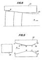
- Fig. 8 is an explanatory view illustrating growths of tongues occurring at a trailing end of a slab;
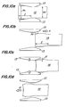
- Fig. 9 is a view showing one example of anvils according to the invention;
- Figs. 10a-10d are views illustrating successive steps of pressing a non-uniform deformation zone of a slab to reduce its width;
- Fig. 11 is a side view of a press reducing the width of slabs according to the invention;
- Fig. 12 is an explanatory view for the method according to the invention using the press shown in Fig. 11;
- Fig. 13 is a view illustrating the configuration of a trailing end of a slab after preforming according to the invention;
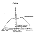
- Fig. 14 is a view illustrating the configuration of trailing ends of a slab after reducing in width, in which "trailing end preforming+continuous pressing" illustrates the present invention and "continuous pressing" illustrates the prior art;
- Fig. 15 is a schematic view illustrating shearing deformations at a leading end of a slab by vertical rolls;
- Fig. 16 is a schematic view illustrating shearing deformations at a trailing end of a slab by vertical rolls;
- Fig. 17 is an explanatory outline view of a slab leading and trailing end pressing preforming apparatus and its preforming process;
- Fig. 18a is an explanatory outline view of a press for pressing overall length of a slab and its pressing;
- Fig. 18b illustrates conditions of the pressing;
- Figs. 19a-19c illustrate steps of producing a crop at a trailing end of a slab;
- Fig. 19d illustrates the crop;
- Fig. 20 is a view illustrating one example of a slab in plan view pressed according to the invention;
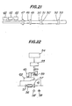
- Fig. 21 illustrates a hot strip mill roughing rolling line used in carrying out the invention;
- Fig. 22 illustrates a controller used in carrying out the invention;
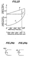
- Fig. 23 is a graph illustrating the relation between reductions and crops at trailing ends by presses and vertical rolls; and
- Figs. 24a and 24b respectively illustrate crops produced in the prior art and the present invention.
- Fig. 1a illustrates a sectional configuration of anvils for a press for reducing widths of slabs according to the invention. In the drawing a
hot slab 2 is transferred relatively to a pair of anvils 1 in a direction shown by an arrow R. The sectional configuration of the anvils comprises an inclined portion AB on an entrance side at a predetermined angle θ to the advancing direction of the slab and a parallel portion BC contiguous with the inclined portion AB. The pair of the anvils 1 is oscillated with anamplitude 2a (Fig. 1 b), while thehot slab 2 is moved to reduce its width by the press-forming. - Referring to Figs. 2a, 2b and 2c illustrating the principal operation for reducing the width of the slab by means of the anvils 1, after the press-forming of the
hot slab 2 has been effected by the anvils 1 (Fig. 2a), thehot slab 2 is advanced by a distance of 2a/tan 8 in the direction R when the anvils 1 are opened (Fig. 2b). The width of the hot slab 1 is then reduced by the anvils when they are closed, so that the reduction areas W are press- formed with wide contact areas of the inclined and parallel portions of the anvils 1 with the hot slab 2 (Fig. 2c) to form one cycle. By repeating such a cycle, the width of thehot slab 2 is continuously reduced from the leading end to the trailing end of the slab 1. - As above mentioned, the inventors of this application have carried out the following experiments to investigate the relationship between tensile stresses and contacting areas of the anvils 1 with
hot slabs 2 affecting the sectional shapes of the slabs. - Widths of hot slabs having initial widths of 1,500 mm and thicknesses of 220 mm were reduced with reduction amounts ΔW (initial widths of the slabs minus widths after press-forming) of 330 mm, with varying inclined angles of the anvils on the entrance side, by means of the continuous width reduction press as shown in Figs. 1a and 1b and Figs. 2a-2c. Fig. 3a illustrates the relationship between the
inclined angles 8 of the anvils and various parameters T/To of sectional shapes of the reduced slabs. In the graph, To indicates the initial thicknesses of the slabs, T the thicknesses after reduction, Tmax the maximum thicknesses of the slabs, Tc and the thicknesses of the slabs at central portions and Te the thicknesses of the slabs at the ends (Fig. 3b). - As can be seen from Fig. 3a, with the anvils having small
inclined angles 6, the thicknesses Te at the ends of the slabs are smaller than the thicknesses Tc at the centres. For example, in the event that after slabs have been pressed by theanvils having angles 8=7.5°, the slabs are horizontally pressed with rolling reductions yH=10%, tensile stresses act on ends 5' of the slabs as shown in Fig. 4. In other words, when the pressed slabs 2' are horizontally rolled in the rolling direction Rr, there are in the ends 5' of the slab from theroll entrance 3 to the roll exit 4zones 6 subjected to large tensile stresses in the rolling direction andzones 7 near to thecenter 5 subjected to compressive stresses. - On the other hand, with the anvils having large inclined angles θ, the thicknesses Te at the ends of the slabs rapidly increase when the θ is more than 18° as shown in Fig. 3a, so that the sections of the slabs become like dog bones having very large ends. Accordingly, when such pressed slabs are horizontally rolled, the centres of the slabs are subjected to large tensile stresses (3 kg/mm2) as shown in Fig. 5.
- Figs. 4 and 5 illustrate internal stresses occurring in the rolled material 2' in rolling directions at right angles to axes of
horizontal rolls 12 horizontally rolling the material 2' therebetween as shown in Fig. 6. - In contrast herewith, with anvils having inclined angles of 10°≦θ≦18°, large tensile stresses did not occur in the slabs even if horizontal rolling was effected after the pressing.
- In more detail, it has been found that in the event that after the widths of hot slabs have been reduced with anvils having
inclined angles 8 of 10°≦θ≦18° on entrance sides, the slabs are horizontally rolled, any large tensile stresses do not occur in the slabs in spite of the initial shapes of the slabs although the shapes after pressing vary somewhat dependent upon the initial shapes of the slabs before pressing. With the large reduction AW of the order of 300-400 mm in press-forming, the slabs exhibit the same results as the above. On the other hand, with the small reduction △W of 50-100 mm, Tmax, Te and Tc become smaller as a whole, so that tensile stresses are smaller than those when the △W is large. However, the distributions of the tensile stresses are substantially the same as in the large △W as shown in Fig. 3a. - It is clearly evident from the above results that there are the optimum values of the
inclined angles 0 of the anvils. If theinclined angles 0 are less than 10°, the thickness at the centre of the slabs increases to a larger extent than that in ends of the slabs, so that the following horizontal rolling causes larger tensile forces in the ends of the slabs, which may cause cracks in the ends. If theinclined angles 0 are more than 18°, large tensile stresses occur in the centers of the slabs resulting in cracks therein. It has been found that with the inclined angles of 10°≦θ≦18°, the horizontal rolling after pressing does not cause any large tensile stresses in the slabs and in width reduction, slabs devoid of defects can be produced. - Fig. 7 illustrates one example of the width sizing series including a press for reducing widths of slabs according to the invention. In the drawing, a pair of anvils 1 are mounted slidably in a
press housing 8. The anvils 1 have the shape comprising inclined portions ofangles 8 on an entrance side in the advancing direction (R) of hot slabs and parallel portions contiguous therewith. The anvils are oscillated with anamplitude 2a by means of hydraulic cylinders 9 for reducing widths of slabs. Pinch rolls 10 intermittently transfer the slabs. A horizontal rolling mill 11 horizontally rolls the slabs after pressing. - With the arrangement of the width sizing series, a hot slab is transferred by the pinch rolls 10 in the direction R into a space between the pair of anvils 1. Then the anvils 1 are pressed into the closed position by the hydraulic cylinders 9 to press the slab so as to reduce its width. Thereafter, while the anvils 1 are being opened, the hot slab is advanced by a predetermined pitch, and the width of the hot slab is reduced in the same manner. By repeating such an operation the reduction in width of the slab is continuously effected and then the hot slab is horizontally rolled by means of the horizontal rolling mill 11.
- Hot slabs having widths of 1,000 mm and thicknesses of 250 mm and widths of 2,200 mm and thicknesses of 220 mm were pressed to reduce their widths with reductions AW=330 mm by means of the width sizing series shown in Fig. 7 using anvils having inclined angles θ=15° on the entrance side oscillated with
amplitudes 2a=80 mm. Thereafter the slabs were horizontally rolled with rolling reduction YH=10%. The quality of the rolled slabs was examined by metallurgical microscopes and supersonic flaw detectors. There was no defect in these slabs. - On the other hand, similar width sizing was effected with anvils which did not have inclined angles or parallel anvils. There were fine cracks in ends of slabs. With anvils having
inclined angles 8=22°, moreover, there were fine cracks in the centres of the slabs. - As can be seen from the above description, according to the invention the width sizing of hot slabs can be continuously effected with any desired widths without any defects such as cracks in the surfaces and the insides of the slabs. As the widths of the slabs can be varied, the invention has significant effects in accomplishing synchronization and continuity of continuous casting installations and hot rolling mills.
- Referring back to Figs. 2a-2c, when a slab is continuously pressed to reduce its width from its leading end to its trailing end, comparatively large tongues occur at the trailing end which lower the yield rate of the slab. It has been found that such tongues occur as shown in Fig. 8. Fig. 8 illustrates deformations of the trailing end of a slab with the lapse of time when
anvils 13 havinginclined angles 8 of 12° are operated withamplitudes 2a of 60 mm with reductions AW of 300 mm. As can be seen from Fig. 8, although tongues do not occur at the stage where the trailing end of the slab is in the proximity of the inclined portions of theanvils 13 so as not to be pressed, tongues start to occur at the stage where theslab 14 has been advanced in the advancing direction R until its traililng end has been advanced to aboutone halfofthewidth of the slab from the rear ends of the inclined portions of theanvils 13. As the slab is advanced, the tongues progressively grow. - In view of the occurrence and growth of the tongues, a first embodiment of the invention uses a particular configuration of anvils. Fig. 9 illustrates one example of such anvils each having pressing surfaces comprising an inclined portion AB on an entrance side in the advancing direction R of a
hot slab 14, a parallel portion BC at an intermediate position and a further inclined portion CD on an exit side. The entrance inclined portion AB is at anangle 6 to the advancing direction R of the slab and the inclined exit portion CD is at an angle θ'. The inclined entrance portion AB and parallel portion BC form pressing surfaces for forming uniform deformed zones including the leading end of the slab. The inclined exit portion CD forms a pressing surface for preforming non-uniform deformed zones by pressing only the trailing end of the slab. - In pressing a slab by means of a press including such anvils, first the slab is pressed to reduce the width starting from the preceding end of the slab with the aid of the inclined entrance portion AB and the parallel portions BC according to the basic operation as above described.
- When the reduction in width arrives at the non-uniform deformed zones at the trailing end of the slab, a treatment of the trailing end of the slab is effected. In other words, for example, referring to Figs. 10a-10d, the slab is pressed to reduce its width in the above manner until the length I of the zone which has not been pressed becomes about one half of the width of the slab (Fig. 10a).Thenthe anvils 13 are opened more than the initial width of the slab and the
slab 14 is further advanced in the direction shown by an arrow R to bring the trailing end into a position enabling the trailing end to contact theinclined exit portions 16 of the anvils (Fig. 10b). In this position of the slab, it is pressed with the aid of theinclined exit portions 16 in directions shown by arrows in Fig. 10c so as to deform the trailing end of the slab into a fishtail to complete a preforming. - The reduction d in the preforming of the trailing end of the slab is dependent upon the reduction ΔW in width and the like. In general, the reduction d is preferably in the range 0.3xΔW to AW. To be exact, however, the reduction d should be determined so as to cancel the tongues at the trailing end of the stab in simply pressing over its length by means of the fishtail at the trailing end caused by the exit inclined portions of the anvils according to the invention. In other words, the reduction d should be determined by the following equation.

- In case of further rolling the pressed slab by the use of a continuous hot rolling mill, it is of course preferable to determine the reduction d in consideration of conditions of roughing rolling so as to make minimum the crops of the roughing rolled material to be cut off.
- After the preforming (Fig. 10c), the
anvils 13 are again opened more than the initial width of the slab and theslab 14 is retracted in a direction shown by an arrow R' (Fig. 10d). Thereafter, while theslab 14 is being advanced, the trailing end is continuously pressed to reduce its width in the same manner as the reduction before the pressing the trailing end as shown in Fig. 10a until the trailing end leaves theanvils 13. In this manner, the tongue at the trailing end of the slab is minimised by treating the trailing end. - Fig. 11 illustrates one example of a press for continuously pressing slabs to reduce their widths.
Anvils 13 are arranged onanvil blocks 18 slidable in a frame of the press and are adapted to be oscillated by means of hydraulic cylinders 19. Theanvils 13 have the configuration as shown in Fig. 9. In the drawing, the advancing direction of theslab 14 is shown by the arrow R.A reference numeral 17 denotes pinch rollers for transferring the slab. - The operation of this aspect of the invention including the control of the transferring of slabs will be explained hereinafter.
- In Fig. 12, a
slab 14 having a width Ws is transferred in a direction shown by an arrow R. When theslab detector 31 detects the leading end of the slab,pinch rollers 30 are lowered. While apulse generator 32 connected to thepinch rollers 30 is tracking the slab, the slab is pressed from the leading end so as to reduce its width to a predetermined width Wp to form a uniform deformed zone. - When the slab detector 31' detects the trailing end of the
slab 14, pinch rollers 30' are lowered and the pulse generator 32' is tracks the trailing end. When the trailing end 14a arrives at a non-uniform deformed zone or a position shown in phantom lines at a distance I from the points B of the anvils, theanvils 13 are opened more than the initial width Ws of the slab. Then the slab is advanced by the pinch rollers 30' until the trailing end of the slab passes by the points C or theslab 14 has moved a distance L. Thereafter the trailing end is pressed with theanvils 13 to effect the preforming of the trailing end with the reduction d. The distance moved by the trailing end of the slab for the preforming may be L+x. In this case, the positions of the anvils where they are stopped from moving toward each other in pressing can be calculated from the inclined angle θ' of the inclined portion CD of theanvils 13, the distance x and the reduction d. - Thereafter, the
anvils 13 are opened more than the initial width Ws of the slab and theslab 14 is retracted to the original position shown in the phantom lines. Then the slab is pressed to reduce the width in the same manner before the preforming of the trailing end until the trailing end 14a has been pressed between theanvils 13. - Slabs having widths of 1,500 mm, thicknesses of 220 mm and lengths of 12,000 mm were pressed to reduce their widths with reduction AW of 300 mm in their uniform deformed zones of the slabs by means of the press shown in Fig. 11 including anvils having inclined entrance angles θ of 12° and inclined exit angles 8' of 20° which are oscillated with frequency of 2n rad/sec and
amplitude 2a of 100 mm. When the length of the slab which had not been pressed was approximately 800 mm, the anvils were opened and the slabs were transferred by the pinch rollers so as to bring trailing ends of the slabs into contact with the inclined exit portions of the anvils. The preforming of the trailing ends was then effected. The reduction d of the preforming in this example was d/2=AW/2=150 mm as shown in Fig. 13, which was dependent upon the reduction AW. - Upon completion of the preforming, the
slabs 14 were retracted and then continuously pressed to reduce the width with reduction AW of 300 mm by the inclined entrance portions and parallel portions of the anvils. Fig. 14 illustrates a configuration of the slabs pressed to reduce the widths indicated by "trailing end preforming plus continuous pressing". - As a comparison slabs were uniformly pressed from their preceding ends to trailing ends without applying the preforming of the trailing ends. A configuration of the slabs is shown in Fig. 14 by the line marked "continuous pressing".
- As can be seen from the comparison of both the configurations in Fig. 14, the slabs treated according to the invention include only very short crops and permit only minimum tongues to occur, so that the configuration of the trailing ends of the slabs is good. On the other hand, the slabs treated by the prior art include long crops and long tongues in their trailing ends.
- As can be seen from the above description, this aspect can produce slabs having very good configurations at the trailing end, devoid of tongues, whilst keeping the high productivity of the width reduction technique by continuous pressing, thereby remarkably improving the yield rate of the slabs.
- Before explaining a second embodiment of the invention, the prior art using a pair of vertical rolls to reduce widths of slabs will be explained. Such vertical rolls may be caliber rolls or simple cylindrical rolls or caliberless rolls with high reduction efficiencies. In both the cases, they have respective inherent disadvantages.
- When edges of a
slab 41 are rolled byvertical rolls 42 as shown in Figs. 15 and 16, shearing deformations in width directions occur in the edges so as to irregularly change the shapes in plan view to produce non-uniform portions called "crops" because the edges are free. In general, these crops are cut off by crop shears on termination of roughing rolling before finishing rolling. This greatly lowers the yield rate of the slabs. - In order to overcome this problem, it has been known to preform preceding and trailing ends of slabs before reducing the widths by vertical rolls (refer to, for example, Japanese Laid-open Patent Applications Nos. 53-40,937; 55-10,363; and 55-48,401
- In these methods, as shown in Fig. 17, a
press 43 for preforming is arranged immediately before vertical rolling mill. After preforming the leading and trailing ends ofslab 41 in the form shown in Fig. 17 by the press, theslab 41 is transferred between the vertical rolls, so that the leading and trailing ends are hardly subjected to reduction in width by the vertical rolls 42. Accordingly, the above shearing deformations are not caused and the shapes of the slabs are substantially good. In this process, however, a vertical rolling mill for reducing the width and a press for preforming arranged immediately thereof must be provided, so that the production line is elongated thus increasing the cost of the installation to making it difficult to realize such an installation. - Moreover, the Japanese Laid-open Patent Application No. 55-153,602 above mentioned discloses the method of preforming four corners of the slab by using vertical rolls, so that it is necessary to provide an exclusive vertical rolling mill. Therefore, this method does not fundamentally solve the problem. Moreover, an extra process is required for preforming the leading and trailing ends of slabs thus remarkably lowering the production efficiency.
- Referring to Figs. 18a and 18b illustrating a press to be used in the second embodiment of the invention, the press includes as main components a pair of
anvils 44 havinginclined angles 6 and a pair ofhydraulic cylinders 45 connected to the respective anvils for driving them. With such a press, aslab 41 having an original width Ws can be pressed to reduce the width by the anvils which are continuously oscillated withamplitude 2a (each anvil) and frequency f by means of thehydraulic cylinders 45. In this case, the required width W of the pressed slab is substantially coincident with the minimum distance between theanvils 44 when moved towards each other. - First the
slab 41 is transferred downward by roller tables (not shown) to the position where it is to be subjected to the reduction in width. Theslab 41 is pressed to reduce its width by the anvils while they are being closed and is then transferred downward at a speed v while the anvils are opened. The speed v is indicated by v=2 af/tan 8. - It has been mentioned in such a pressing, however, that when slabs are pressed to reduce their widths by anvils, tongues often occur on trailing ends of the slabs to lower the yield rate (Figs. 19a-19d).
- The second embodiment of the invention resides in the discovery that shapes of crops are determined by the deformations on pressing in conjunction with the shearing deformations on vertical rolling thereafter.
- In more detail, in an initial stage of pressing the
slab 41 is continuously pressed from its leading end to reduce its width by means ofanvils 44 oscillated to open and close with a predetermined minimum open distance until the reduction in width arrives in the proximity of the trailing end of theslab 41. When the reduction arrives in the proximity of the trailing end, the predetermined minimum open distance is changed such that the pressed width near the trailing end of the slab is wider than the width W of the already pressed slab. With such an open distance of the anvils, the pressing of the slab is effected. In this case, the configuration of the slab after completion of pressing is shown in Fig. 20 in a plan view, wherein the width W' of the slab at the trailing end having a length I is wider than the predetermined width W of the pressed slab. - At this stage, the trailing end of the slab forms a tongue larger than is desired. According to the invention, however, after this pressing over the length of the slab, the slab is rolled in roughing rolling by vertical rolls to reduce the width of the slab, so that the fishtail due to the shearing deformations caused by the vertical rolls just cancels the tongue caused in the above pressing by the anvils, with the result that on shearing the crop by means of crop shears before the final finishing rolling, the slab hardly requires any crop to be cut to obtain a complete slab.
- In this manner, following to pressing the overall length of the slab, the trailing end is rolled to reduce its width with a predetermined reduction larger than that of the steady portion of the slab, thereby controlling the slab in a good configuration. Such an effect will be clearly understood by referring to the following example.
- Fig. 21 illustrates a hot strip roughing rolling line relating to the third embodiment of the invention. This line includes
heating furnaces 46, apress 47 for pressing the overall length of slabs, verticalroll rolling mills roll rolling mills press 47 is arranged between theheating furnaces 46 and the first rolling mills (48, 49). The slabs transferred from the heating furnaces are subjected to the sizing of thepress 47 and reduced in their widths and are then transferred into the roughing rolling mill. Thepress 47 for pressing the overall width of the slabs is controlled by a device shown in Fig. 22. - Referring to Fig. 22, the width W of the slab after pressing is determined by arithmetic operation in an
upper computer 54 according to an equation W=f (W F, Hf, Ws, Hs, HR, T, S) using width WF of hot rolled products, thickness H, of the products, width Ws of slabs, thickness Hs of the slabs, thickness HR of sheet bars, heating temperature T and kinds of sheet S upon receipt demand of rolling. At the same time, theamplitude 2a and frequency f in pressing are determined. These determined values are transmitted into acontroller 55 for controlling thepress 47. Moreover, the trailing end compensation width a and the length I are calculated using equations a=f' (W, Ws, WF, Hs, HF, HR, T, S) and I=f' (W, Ws, WF, Hs, HF, HR, T, S). These calculated values are also transmitted into thecontroller 55. - The minimum open distance W of the anvils, and the
amplitude 2a and frequency f of pressing are set by arithmetic operation on the basis of these inputted data in the controller 15. - When the slab detector 58 detects the leading end of the
slab 41, thecontroller 55 for the press generates a signal to start the oscillation of theanvils 44 through thehydraulic selector valve 59 andhydraulic cylinders 45. At the same time, moreover, when the slab detector 58' detects the leading end of theslab 41, pinch rolls 57 and the buckling preventingdevice 56 are lowered so as to detect distance advanced by the slab by the pinch rolls to effect the position tracking of theslab 41. The tracking of theslab 41 by the pinch rolls 57 is controlled by a pulse generator (not shown) provided thereat. - In this embodiment, the slab is pressed to reduce the width by the anvils oscillated with
amplitude 2a and frequency f from the leading end to the proximity of the trailing end of the slab as above described. Pressing in a manner differ- entfrom this may of course be used. For example, only the leading end of the slab is pressed by the anvils with amplitude and frequency different from those in the above embodiment or the intermediate portion of the slab is pressed by the anvils with varying amplitude and frequency. These modifications are within the scope of the invention. - In this manner, starting from the leading end of the slab, it is pressed to reduce the width. When the slab detector 58 detects the trailing end of the
slab 41, the operation of thepress 47 is stopped and at this time the tracking of the trailing end of the slab is effected. Thereafter, the trailing end of the slab is pressed to reduce the width from the location immediately before the end is in contact with theanvils 44 over the length from I to 1+2a/ tan θ. - In more detail, the minimum open distance W of the anvils at the beginning of the operation is changed into a new minimum open distance W'=W+a where a is a trailing end compensation width. At the same time, the
amplitude 2a and the frequency f of the anvils are also changed to new amplitude
- By the above pressing, the
slab 41 as shown in Fig. 20 is obtained. In this embodiment, thereafter, the slab is roughing-rolled through one pass in thefirst rolling mills second rolling mills third rolling mills - A method of determining the trailing end compensation width a for pressing the trailing end of the slab according to the invention will be explained in detail hereinafter.
- It has been mentioned that crops are quite different respectively in case of pressing by a press and case of vertical rolling by vertical roll mills for all the reduction ΔW(=Wa--W). It is important however that in carrying out the reduction AW in width of a slab, if a reduction of k% or
-


- In view of this, the inventors investigated the relation between the reductions in width and crops at trailing ends of slabs by measuring crops when various reductions of 0-450 mm were effected by only the press and by only the vertical rolls. The results are shown in Fig. 23. In this case, the thicknesses of the slabs were changed from 220 mm to 45 mm and the widths are from 1,500 mm to 1,050-1,450 mm. In the drawing, a line E indicates the relation between the reduction in width and the tongue at the trailing end of the slab when the slab is roughing-rolled after pressing to reduce the width, and a line F indicates the relation between the reduction and the tongue by the vertical rolls. It can be seen from this drawing that when the total reduction in width is 450 mm, the crop is substantially completely eliminated if the trailing end compensation width a is 80 mm and the compensation width is reduced by the vertical rolls (refer to a point Z in Fig. 23). In other words, it means that the portion of the slab other than its trailing end is pressed with reduction of 450 mm and the trailing end is pressed with reduction of 370 mm (=450 mm-80 mm), so that a substantial portion of the slab is rolled by the vertical rolls with a very small reduction and the trailing end is rolled with reduction of 80 mm. In fact, the initial reduction by pressing may be determined to be substantially equal to the reduction of 450 mm which is required to obtain the aimed width of the slab, or in other words to be somewhat wider than the aimed width, thereby obtaining sound slabs.
- With the trailing end compensation length I, it has been found that the relation shown in Fig. 23 can be obtained, if the compensation length I is more than 25% of the length of the slab which is in contact with the inclined portions of the anvils in pressing the intermediate portion of the slab. In obtaining slabs having thicknesses of 45 mm and widths of 1,050 mm from slabs having thicknesses of 220 mm and widths of 1,500 mm, for example, after the trailing ends of the slabs were pressed with trailing end compensation width a=80 mm and length 1=350 mm, the rolling was effected (according to the present invention) and also after slabs were pressed without the compensation of the trailing ends, the rolling was effected (prior art). Crops produced in the prior art were very long as much as 820 mm as shown in Fig. 24a. On the other hand, crops produced in the slabs according to the invention were considerably shortened to only 55 mm.
- As can be seen from the above explanation, according to the second embodiment, slabs having much better shapes in plan view are obtained to improve the yield rate and also the pressing to reduce the width can be continuously effected without stopping the slab as is necessary in the prior art, thereby avoiding lowering the yield rate. As the reduction by vertical rolls is very small when utilizing the vertical rolls of roughing mills according to the invention, the reduction in width of slabs can be accomplished with installations whose number is one less than those in the prior art process using the preforming press and the exclusive vertical rolling apparatus, thereby avoiding the disadvantage of an extended operating line.
- While the invention has been particularly shown and described with reference to preferred embodiments thereof, it will be understood by those skilled in the art that the foregoing and other changes in form and details can be made therein without departing from the scope of the claims.
Claims (12)
Applications Claiming Priority (6)
| Application Number | Priority Date | Filing Date | Title |
|---|---|---|---|
| JP59059531A JPS60203303A (en) | 1984-03-29 | 1984-03-29 | Method for rolling hot slab in its width direction by press |
| JP59059532A JPH0683841B2 (en) | 1984-03-29 | 1984-03-29 | Width reduction method of hot slab |
| JP59531/84 | 1984-03-29 | ||
| JP59532/84 | 1984-03-29 | ||
| JP5953384A JPS60203305A (en) | 1984-03-29 | 1984-03-29 | Method and device for rolling hot slab in width direction by press |
| JP59533/84 | 1984-03-29 |
Publications (4)
| Publication Number | Publication Date |
|---|---|
| EP0157575A2 EP0157575A2 (en) | 1985-10-09 |
| EP0157575A3 EP0157575A3 (en) | 1987-02-04 |
| EP0157575B1 true EP0157575B1 (en) | 1990-05-23 |
| EP0157575B2 EP0157575B2 (en) | 1996-04-10 |
Family
ID=27296912
Family Applications (1)
| Application Number | Title | Priority Date | Filing Date |
|---|---|---|---|
| EP85302071A Expired - Lifetime EP0157575B2 (en) | 1984-03-29 | 1985-03-26 | Method for reduction in width of slabs by pressing and press for the same |
Country Status (4)
| Country | Link |
|---|---|
| EP (1) | EP0157575B2 (en) |
| KR (1) | KR900004152B1 (en) |
| AU (1) | AU567608B2 (en) |
| DE (1) | DE3577816D1 (en) |
Cited By (4)
| Publication number | Priority date | Publication date | Assignee | Title |
|---|---|---|---|---|
| EP0224333A2 (en) * | 1985-11-22 | 1987-06-03 | Kawasaki Steel Corporation | Press apparatus for reducing widths of hot slabs |
| EP0270245A2 (en) * | 1986-12-01 | 1988-06-08 | Kawasaki Steel Corporation | Method of reducing slab in widthwise direction |
| WO1992010318A1 (en) * | 1990-12-14 | 1992-06-25 | Davy Mckee (Sheffield) Limited | Width reduction of metal slab |
| US5331833A (en) * | 1991-03-01 | 1994-07-26 | Sms Schloemann-Siemag Aktiengesellschaft | Method of operating an upsetting press |
Families Citing this family (3)
| Publication number | Priority date | Publication date | Assignee | Title |
|---|---|---|---|---|
| US4930207A (en) * | 1988-06-07 | 1990-06-05 | Kawasaki Steel Corp. | Method and apparatus for continuous compression forging of continuously cast steel |
| RU2525954C2 (en) * | 2012-10-16 | 2014-08-20 | Открытое Акционерное Общество "Тяжпрессмаш" | Method of production of billets at rolling mills |
| AT513701B1 (en) * | 2012-12-13 | 2015-06-15 | Gfm Gmbh | Method for forging a workpiece |
Family Cites Families (10)
| Publication number | Priority date | Publication date | Assignee | Title |
|---|---|---|---|---|
| US3333452A (en) * | 1965-03-03 | 1967-08-01 | Sendzimir Inc T | Reduction of thick flat articles |
| DE1960418A1 (en) * | 1969-12-02 | 1971-06-24 | Horst Schenk | Composite multi jaw tool for forging - machine |
| US3921429A (en) * | 1974-04-11 | 1975-11-25 | Tadeusz Sendzimir | Process and apparatus for modifying the cross section of a slab |
| AU511207B2 (en) * | 1975-08-04 | 1980-07-31 | Ccl Systems Limited | Swaging press and dies |
| JPS5666305A (en) * | 1979-10-31 | 1981-06-04 | Hitachi Ltd | Method and apparauts for edging slab |
| SE7910161L (en) * | 1979-12-10 | 1981-06-11 | Per Olof Strandell | PROCEDURE AND DEVICE FOR FORMING PROFILES |
| JPS5853301A (en) * | 1981-09-24 | 1983-03-29 | Hitachi Ltd | Preforming method for plate material by pressing in broadside rolling |
| JPS58215202A (en) * | 1982-06-08 | 1983-12-14 | Kawasaki Steel Corp | Method and device for preforming preceding and succeeding end of slab by pressing |
| EP0112516B1 (en) * | 1982-12-01 | 1988-05-11 | Hitachi, Ltd. | Press apparatus for reducing slab width |
| JPS59179201A (en) * | 1983-03-30 | 1984-10-11 | Hitachi Ltd | Adjusting method of slab width |
-
1985
- 1985-03-26 DE DE8585302071T patent/DE3577816D1/en not_active Expired - Lifetime
- 1985-03-26 EP EP85302071A patent/EP0157575B2/en not_active Expired - Lifetime
- 1985-03-29 KR KR1019850002121A patent/KR900004152B1/en not_active IP Right Cessation
- 1985-03-29 AU AU40531/85A patent/AU567608B2/en not_active Expired
Cited By (8)
| Publication number | Priority date | Publication date | Assignee | Title |
|---|---|---|---|---|
| EP0224333A2 (en) * | 1985-11-22 | 1987-06-03 | Kawasaki Steel Corporation | Press apparatus for reducing widths of hot slabs |
| EP0224333A3 (en) * | 1985-11-22 | 1987-10-28 | Kawasaki Steel Corporation | Press apparatus for reducing widths of hot slabs and slab widths reducing method using the apparatus |
| US4760728A (en) * | 1985-11-22 | 1988-08-02 | Kawasaki Steel Corporation | Method for reducing widths of hot slabs |
| EP0270245A2 (en) * | 1986-12-01 | 1988-06-08 | Kawasaki Steel Corporation | Method of reducing slab in widthwise direction |
| EP0270245A3 (en) * | 1986-12-01 | 1988-09-21 | Kawasaki Steel Corporation | Method of reducing slab in widthwise direction |
| US4848127A (en) * | 1986-12-01 | 1989-07-18 | Kawasaki Steel Corporation | Method of reducing slab in widthwise direction |
| WO1992010318A1 (en) * | 1990-12-14 | 1992-06-25 | Davy Mckee (Sheffield) Limited | Width reduction of metal slab |
| US5331833A (en) * | 1991-03-01 | 1994-07-26 | Sms Schloemann-Siemag Aktiengesellschaft | Method of operating an upsetting press |
Also Published As
| Publication number | Publication date |
|---|---|
| AU4053185A (en) | 1985-10-03 |
| EP0157575B2 (en) | 1996-04-10 |
| AU567608B2 (en) | 1987-11-26 |
| DE3577816D1 (en) | 1990-06-28 |
| EP0157575A2 (en) | 1985-10-09 |
| KR850007001A (en) | 1985-10-30 |
| EP0157575A3 (en) | 1987-02-04 |
| KR900004152B1 (en) | 1990-06-18 |
Similar Documents
| Publication | Publication Date | Title |
|---|---|---|
| CN1103647C (en) | Method and arrangement for producing hot-rolled strip | |
| US5323951A (en) | Method of joining steel sheet bars in hot rolling and a continuous hot rolling method | |
| US5094094A (en) | Hot-rolling equipment and a method of hot-rolling a slab | |
| EP0157575B1 (en) | Method for reduction in width of slabs by pressing and press for the same | |
| US4760728A (en) | Method for reducing widths of hot slabs | |
| EP1145777B1 (en) | Method for manufacturing hot-rolled sheet steel | |
| EP0665296A1 (en) | Process and plant for manufacturing hot-rolled strip steel | |
| JP3528504B2 (en) | Manufacturing method of extra thick steel plate | |
| US4067220A (en) | Rolling of billets | |
| KR20050092433A (en) | Method and device for producing continuously cast steel slabs | |
| US4363234A (en) | Method and apparatus for forging sections | |
| CN109794509A (en) | Hot strip hot roll bending slitting roller, hot roll bending slitting system, technique and production line | |
| JPH0330441B2 (en) | ||
| JPH03128122A (en) | Accelerated cooling method of thick steel plate | |
| JPS60203304A (en) | Method for rolling hot slab in its width direction | |
| JPS61235002A (en) | Method and apparatus for molding slab | |
| JPH0324282B2 (en) | ||
| CN117443946A (en) | Method for controlling bending defect of hot-rolled intermediate billet | |
| JPS6354444B2 (en) | ||
| JPS60203302A (en) | Method and device for rolling hot slab in width direction by press | |
| JPH0446641B2 (en) | ||
| JP2000140906A (en) | Manufacture of ultra-heavy steel plate at extremely large reduction ratio | |
| JP2000079402A (en) | Rolling device for metal base stock | |
| KR20040019734A (en) | Stepped defects control method of slab sizing press in hot strip mill | |
| JPH02151302A (en) | Method for rolling shape steel |
Legal Events
| Date | Code | Title | Description |
|---|---|---|---|
| PUAI | Public reference made under article 153(3) epc to a published international application that has entered the european phase |
Free format text: ORIGINAL CODE: 0009012 |
|
| AK | Designated contracting states |
Designated state(s): DE FR GB |
|
| PUAL | Search report despatched |
Free format text: ORIGINAL CODE: 0009013 |
|
| AK | Designated contracting states |
Kind code of ref document: A3 Designated state(s): DE FR GB |
|
| 17P | Request for examination filed |
Effective date: 19870723 |
|
| 17Q | First examination report despatched |
Effective date: 19881223 |
|
| GRAA | (expected) grant |
Free format text: ORIGINAL CODE: 0009210 |
|
| AK | Designated contracting states |
Kind code of ref document: B1 Designated state(s): DE FR GB |
|
| REF | Corresponds to: |
Ref document number: 3577816 Country of ref document: DE Date of ref document: 19900628 |
|
| ET | Fr: translation filed | ||
| PLBI | Opposition filed |
Free format text: ORIGINAL CODE: 0009260 |
|
| 26 | Opposition filed |
Opponent name: SMS SCHLOEMANN-SIEMAG AG Effective date: 19900922 |
|
| PUAH | Patent maintained in amended form |
Free format text: ORIGINAL CODE: 0009272 |
|
| STAA | Information on the status of an ep patent application or granted ep patent |
Free format text: STATUS: PATENT MAINTAINED AS AMENDED |
|
| 27A | Patent maintained in amended form |
Effective date: 19960410 |
|
| AK | Designated contracting states |
Kind code of ref document: B2 Designated state(s): DE FR GB |
|
| ET3 | Fr: translation filed ** decision concerning opposition | ||
| APAC | Appeal dossier modified |
Free format text: ORIGINAL CODE: EPIDOS NOAPO |
|
| APAC | Appeal dossier modified |
Free format text: ORIGINAL CODE: EPIDOS NOAPO |
|
| REG | Reference to a national code |
Ref country code: GB Ref legal event code: IF02 |
|
| PGFP | Annual fee paid to national office [announced via postgrant information from national office to epo] |
Ref country code: FR Payment date: 20040309 Year of fee payment: 20 |
|
| PGFP | Annual fee paid to national office [announced via postgrant information from national office to epo] |
Ref country code: GB Payment date: 20040324 Year of fee payment: 20 |
|
| PGFP | Annual fee paid to national office [announced via postgrant information from national office to epo] |
Ref country code: DE Payment date: 20040408 Year of fee payment: 20 |
|
| PG25 | Lapsed in a contracting state [announced via postgrant information from national office to epo] |
Ref country code: GB Free format text: LAPSE BECAUSE OF EXPIRATION OF PROTECTION Effective date: 20050325 |
|
| REG | Reference to a national code |
Ref country code: GB Ref legal event code: PE20 |
|
| APAH | Appeal reference modified |
Free format text: ORIGINAL CODE: EPIDOSCREFNO |