EP0157570A2 - Latch and detent mechanism for sliding tray - Google Patents
Latch and detent mechanism for sliding tray Download PDFInfo
- Publication number
- EP0157570A2 EP0157570A2 EP85302059A EP85302059A EP0157570A2 EP 0157570 A2 EP0157570 A2 EP 0157570A2 EP 85302059 A EP85302059 A EP 85302059A EP 85302059 A EP85302059 A EP 85302059A EP 0157570 A2 EP0157570 A2 EP 0157570A2
- Authority
- EP
- European Patent Office
- Prior art keywords
- tray
- detent
- bar
- finger
- latch bar
- Prior art date
- Legal status (The legal status is an assumption and is not a legal conclusion. Google has not performed a legal analysis and makes no representation as to the accuracy of the status listed.)
- Granted
Links
Images


Classifications
-
- E—FIXED CONSTRUCTIONS
- E05—LOCKS; KEYS; WINDOW OR DOOR FITTINGS; SAFES
- E05B—LOCKS; ACCESSORIES THEREFOR; HANDCUFFS
- E05B65/00—Locks or fastenings for special use
- E05B65/46—Locks or fastenings for special use for drawers
-
- Y—GENERAL TAGGING OF NEW TECHNOLOGICAL DEVELOPMENTS; GENERAL TAGGING OF CROSS-SECTIONAL TECHNOLOGIES SPANNING OVER SEVERAL SECTIONS OF THE IPC; TECHNICAL SUBJECTS COVERED BY FORMER USPC CROSS-REFERENCE ART COLLECTIONS [XRACs] AND DIGESTS
- Y10—TECHNICAL SUBJECTS COVERED BY FORMER USPC
- Y10T—TECHNICAL SUBJECTS COVERED BY FORMER US CLASSIFICATION
- Y10T292/00—Closure fasteners
- Y10T292/08—Bolts
- Y10T292/1043—Swinging
- Y10T292/1075—Operating means
- Y10T292/1083—Rigid
- Y10T292/1091—Spring-arm catch
Landscapes
- Drawers Of Furniture (AREA)
- Casings For Electric Apparatus (AREA)
Abstract
Description
- This invention relates generally to slide mechanisms for drawers and trays, and relates more particularly to a latch and detent mechanism for use with a sliding tray.
- Sliding trays are useful for a variety of purposes. One use for sliding trays is in computer console cabinets, where a sliding tray may be used to provide a horizontal work surface for the placement of a keyboard and work materials. When the computer is in use, the sliding tray is extended from the cabinet and is locked into position. It is desirable to lock the sliding tray in its extended position to prevent inadvertent retraction. When the computer is not in use, the sliding tray is retracted into the cabinet to save floor space. It is also desirable to lock the sliding tray in its retracted position to prevent extension during shipping and handling. Other locked positions intermediate to the fully extended and fully retracted positions are also useful to allow the user to extend and lock the sliding tray to the position best suited for his or her environment.
- Sliding trays with locking mechanisms have been known in the prior art. They have typically included a tray mounted on drawer slides with locking provided by a mechanism coupled to the drawer slides. Such sliding trays were expensive due to the complexity of the locking mechanisms. Many such sliding trays were capable of locking only at the fully extended position. They were difficult to unlock where the drawer slides had been hidden from sight to improve visual appearances. In addition, they suffered from lack of rigidity due to backlash in the locking mechanisms.
- In accordance with the illustrated preferred embodiment, the present invention provides a latch and detent mechanism for use with a sliding tray mounted in a cabinet. The mechanism includes a stationary detent bar having one or more detent slots, a latch bar that is pivotably coupled to the sliding tray with a finger at one end for engaging a detent slot to lock the tray in positron, handle means coupled to the latch bar for disengaging the finger to unlock the tray, and biasing means for urging the finger toward the detent slot.
- In the preferred embodiment, the invention includes two molded plastic parts plus a coil spring. Both the detent bar and the latch bar are positioned beneath the tray with their axes parallel to the direction of tray movement. A pivot pin located near the center of the latch bar is coupled to the underside of the tray to provide a pivotable mounting for the latch bar. The finger of the latch bar is disposed toward the aft end of the tray and a handle is disposed toward the forward end. The coil spring is placed between the latch bar and the tray at a position between the finger and the pivot pin. The coil spring forces the finger downward into a detent slot to lock the position of the tray. To reposition the tray, the handle end of the latch bar is forced downward, which lifts the finger from the detent slot and unlocks the tray.
- The preferred embodiment also includes stops for defining the fully extended and fully retracted positions of the tray. The detent bar includes forward and aft stop members, and the latch bar includes a stop member as well. The stop member of the latch bar contacts the forward stop member of the detent bar at the fully extended position, and it contacts the aft stop member at the fully retracted position. Detent slots are provided to lock the tray at both the fully extended and the fully retracted positions.
- Backlash is avoided by the use of detent slots with two tapered side walls and a finger with two correspondingly tapered faces. When the finger is engaged with a detent slot, the coil spring ensures intimate contact between the walls of the detent slot and the faces of the finger.
- The latch and detent mechanism of the present invention provides several advantages over other prior art mechanisms. A major advantage is low cost, since the invention consists of two molded plastic parts and a standard coil spring. A further advantage is that several locking positions for the tray are provided. Another advantage is that backlash is eliminated to provide stability at each of the several locking positions. Still another advantage is that the latch and detent mechanism of the present invention and the drawer slides of the tray are positioned beneath the tray, thereby presenting a pleasing visual appearance.
-
- Figure 1 is a perspective view of a cabinet with a sliding tray that incorporates a latch and detent mechanism according to the present invention.
- Figure 2 is a top perspective view of a detent bar of the latch and detent mechanism of the present invention.
- Figure 3 is a bottom perspective view of a latch bar of the latch and detent mechanism of the present invention.
- Figure 4 is side elevation sectional view of the sliding tray and the latch and detent mechanism, and is taken along section line A-A shown in Figure 1. Figure 4 shows the sliding tray in a retracted position.
- Figure 5 is side elevation sectional view of the sliding tray and the latch and detent mechanism, and is taken along section line A-A shown in Figure 1. Figure 5 shows the sliding tray in an extended position.
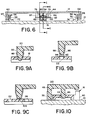
- Figure 6 is a front elevation sectional view of the sliding tray and the latch and detent mechanism, and is taken along section line B-B shown in Figure 4.
- Figure 7 is a side elevation sectional view of a pivot pin of the latch bar of Figure 3, and is taken along section line C-C shown in Figure 6.
- Figure 8 is a front elevation sectional view of a coil spring, and is taken along section line D-D shown in Figure 4.
- Figures 9a, 9b, and 9c are side elevation sectional views of a finger of the latch bar of Figure 3 and a detent slot of the detent bar of Figure 2, and are taken along section line E-E shown in Figure 6.
- Figure 10 is a front elevation sectional view of the latch bar and the detent bar, and is taken along section line F-F shown in Figure 4.
- The preferred embodiment of the present invention is a latch and detent mechanism for use with a sliding tray. Figure 1 shows a
cabinet 10 with a slidingtray 12 in an extended position. The tray includes ahandle 14 that is pushed downward to unlock the tray for movement alongdirection 16 to another position. A pair of drawer slides and a latch and detent mechanism are coupled to the underside oftray 12, as will be described below. The drawer slides support and guide the tray between the extended position shown in Figure 1 and a retracted position with the tray retracted into the cabinet. The latch and detent mechanism provides means for locking the tray at any of several locking positions.Cabinet 10 could be used, for example, as a computer console cabinet, with a keyboard positioned on the tray and a computer terminal or monitor positioned on top of the cabinet. - The latch and detent mechanism includes a
detent bar 18 and alatch bar 20, shown, respectively, in Figures 2 and 3.Latch bar 20 is pivotably coupled to the underside oftray 12.Detent bar 18 is positioned beneath the latch bar, and is fixedly mounted to the cabinet. The axes of bothdetent bar 18 andlatch bar 20 are oriented parallel todirection 16. -
Detent bar 18 is generally elongate in shape with one or moredetent slots forward end 30 of the detent bar,shoulders aft end 36,shoulders Forward end 30 is oriented toward the front-ofcabinet 10, whileaft end 36 is oriented toward the rear of the cabinet. -
Latch bar 20, is also generally elongate in shape.Handle 14 is disposed atforward end 42 of the latch bar. Apivot pin 44 is transversely oriented to the axis of the latch bar and is affixed near the center of the latch bar. Three downward-pointingfingers aft end 52 of the latch bar. - Turning now to Figures 4 and 5, the relative positioning of
tray 12,detent bar 18, and latchbar 20 may be seen. In Figure 4, the tray is shown in its fully retracted position. At the fully retracted position, second andthird fingers shoulders first finger 46 with respect detent slot 22 (shown in Figure 2). Acoil spring 54, which is located between the latch bar and the tray at a position between the fingers andpivot pin 44, provides a downward force on the first finger. This downward force causes the first finger to enter into and engagedetent slot 22. When the finger has engaged a detent slot, the tray is in a locked position. - In Figure 5, the tray is shown in its fully extended position. To release the tray from the locked position shown in Figure 4, a downward force is applied to handle 14. The downward force causes the latch bar to pivot about
pivot pin 44, which compressescoil spring 54 and lifts thefirst finger 46 from the detent slot. With the first finger disengaged from the detent slot, the tray may be pulled forward untilfingers contact shoulders handle 14 is released, the first finger will engagedetent slot 28 to lock the tray in the fully extended position. - Details of mounting provisions for the latch and detent mechanism and the tray are shown in Figure 6. Two drawer slides 56 and 58 are provided to couple
tray 12 tocabinet 10.Runners vertical sides Frames brackets - Mounting provisions for
latch bar 20 are shown in Figures 6 and 7. Tworibs Pivot pin 44 is placed innotch 80 and is retained by aplate 82.Plate 82 is secured to the underside of the tray bystandoffs - In Figure 8, the mounting provisions for
coil spring 54 are shown. The coil spring fits over atab 88 that projects downward from the underside oftray 12, and atab 90 that projects upward from the topside oflatch bar 20. The coil spring is a helically wound compression spring that provides a downward force on the latch bar. Alternatively, biasing means could be provided by a tension spring located betweenpivot pin 44 and handle 14, or by a torsion spring located at the pivot pin. - In Figures 9a, 9b, and 9c, the engagement between first finger,46 and
detent slot 22 is illustrated. Forward andaft side walls detent slot 22 are inwardly tapered and form a V-shaped slot. Forward and aft faces 96 and 98 offirst finger 46 are tapered at the same angle as the side walls. When fully engaged, the faces of the first finger contact the side walls of the detent slot. Downward pressure exerted by the coil spring ensures contact between both forward and aft surfaces. Such contact eliminates backlash in the tray, and provides a stable locking position. - Selection of the angle of taper depends upon the amount of tray locking desired, as well as upon the material used for the latch bar. The amount of tray locking is determined by the taper angle and the downward force provided by the coil spring. If the tray is bumped, the finger will pop out of the detent slot if an upward force greater than the spring force is generated. A shallow taper angle will generate a greater upward force for a given horizontal force than will a steep taper angle. However, it is desirable for the finger to pop out of its detent slot instead of shearing off if the tray is struck with great force. In the preferred embodiment, the latch bar is composed of a molded plastic material, such as, for example, glass reinforced polystyrene. It has been found that a taper angle of ten to fifteen degrees provides a sufficient degree of tray locking while protecting the first finger from excessive shear forces.
- In Figure 9c, the tip of the first finger is shown in contact with the upper surface of the detent bar. This happens when the tray is unlocked and moved, and the handle is then released. If the tray is moved either way, the finger will fall into a detent slot. A rounded tip 100 is provided at the tip of the first finger for contacting the surface of the detent bar. The rounded tip may be composed of a low friction material to reduce sliding friction and noise.
- Another view of an engaged first finger is shown in Figure 10. Note that the lateral faces of
first finger 46 are vertical, while the lateral side walls ofdetent slot 22 are tapered. Since tray backlash is eliminated by contact between the forward and aft tapered faces and side walls, the lateral faces and side walls need not contact. Clearance is provided between the lateral faces and side walls to facilitate engagement and retraction of the first finger. - From the above description, it will be apparent that the invention disclosed herein provides a novel and advantageous apparatus for a latch and detent mechanism for use with a sliding tray. As will be understood by those familiar with the art, the invention may be embodied in other -specific forms without departing from the spirit or essential characteristics thereof. Accordingly, the disclosure of the present invention is intended to be illustrative, but not limiting, of the scope of the invention, which is set forth in the following claims.
Claims (12)
Applications Claiming Priority (2)
| Application Number | Priority Date | Filing Date | Title |
|---|---|---|---|
| US06/593,163 US4600255A (en) | 1984-03-26 | 1984-03-26 | Latch and detent mechanism for sliding tray |
| US593163 | 1990-10-05 |
Publications (3)
| Publication Number | Publication Date |
|---|---|
| EP0157570A2 true EP0157570A2 (en) | 1985-10-09 |
| EP0157570A3 EP0157570A3 (en) | 1986-07-30 |
| EP0157570B1 EP0157570B1 (en) | 1989-05-17 |
Family
ID=24373648
Family Applications (1)
| Application Number | Title | Priority Date | Filing Date |
|---|---|---|---|
| EP85302059A Expired EP0157570B1 (en) | 1984-03-26 | 1985-03-25 | Latch and detent mechanism for sliding tray |
Country Status (5)
| Country | Link |
|---|---|
| US (1) | US4600255A (en) |
| EP (1) | EP0157570B1 (en) |
| JP (1) | JPS60156776U (en) |
| CA (1) | CA1237462A (en) |
| DE (1) | DE3570259D1 (en) |
Cited By (2)
| Publication number | Priority date | Publication date | Assignee | Title |
|---|---|---|---|---|
| EP0460277A2 (en) * | 1990-06-08 | 1991-12-11 | Hazet-Werk Hermann Zerver GmbH & Co. KG | Locking device for drawers |
| GB2281937A (en) * | 1993-09-21 | 1995-03-22 | Smart Systems Limited | An anti-theft locking mechanism that controls access |
Families Citing this family (47)
| Publication number | Priority date | Publication date | Assignee | Title |
|---|---|---|---|---|
| US4844305A (en) * | 1986-10-15 | 1989-07-04 | Mckneely James W | Cargo compartment organizer |
| DE3825828A1 (en) * | 1988-07-29 | 1990-02-01 | Happich Gmbh Gebr | CONTAINER, ESPECIALLY ASHTRAY FOR VEHICLES |
| SE469869B (en) * | 1988-09-02 | 1993-10-04 | Sintek Int Ab | Locking device for moving slopes, shelves, drawers and the like |
| US4892368A (en) * | 1988-10-03 | 1990-01-09 | Malgo Corporation | Drawer slide |
| US4931978A (en) * | 1988-10-21 | 1990-06-05 | Ring King Visibles | Computer support device with power control devices |
| US5002402A (en) * | 1989-10-30 | 1991-03-26 | Standard Precision, Inc. | Unhanded slide latch device |
| US5094516A (en) * | 1990-08-15 | 1992-03-10 | Tempress Incorporated | Storage bin |
| US5248195A (en) * | 1992-08-06 | 1993-09-28 | Chern Jia Enterprise Co., Ltd. | Separable bottom mounted drawer slide assembly |
| US5287245A (en) * | 1992-11-13 | 1994-02-15 | International Business Machines Corporation | Computer having ejectable keyboard ejected by damping device |
| US5405195A (en) * | 1994-03-01 | 1995-04-11 | General Devices Co., Inc. | Automatic release mechanism for telescoping slide assembly |
| US5607213A (en) * | 1995-04-03 | 1997-03-04 | Snap-On Technologies, Inc. | Sliding drawer tray |
| US5961193A (en) * | 1997-11-07 | 1999-10-05 | General Devices Co., Inc. | Release-control mechanism for telescoping slide assembly |
| US7134714B1 (en) | 1998-06-22 | 2006-11-14 | Responsible Me, Inc. | Highchair helper improvements |
| US6256193B1 (en) * | 1998-09-22 | 2001-07-03 | Speck Product Design, Inc. | Vertical docking and positioning apparatus for a portable computer |
| US6971729B1 (en) | 2000-05-01 | 2005-12-06 | Accuride International, Inc. | Self-closing slide |
| AU2001259231A1 (en) | 2000-05-01 | 2001-11-12 | Accuride International, Inc. | Self-closing slide and mechanism for a self-closing slide |
| US20060082266A1 (en) * | 2000-05-01 | 2006-04-20 | Le Hai D | Self-moving slides and self-moving mechanisms |
| DE60102381T2 (en) | 2000-07-13 | 2005-03-17 | Bakker & Elkhuizen Holding B.V. | SUPPORT AND USE OF A PORTABLE COMPUTER |
| US6707664B2 (en) | 2001-02-11 | 2004-03-16 | Micron Technology, Inc. | Expandable keyboard for portable computers |
| JP3874260B2 (en) * | 2002-04-10 | 2007-01-31 | 豊田合成株式会社 | Vehicle drawer device |
| US6932426B2 (en) * | 2002-04-23 | 2005-08-23 | Graco Children's Products Inc. | Tray system for a seat apparatus |
| US20050012007A1 (en) * | 2003-07-16 | 2005-01-20 | Chien-Kuo Chang | Sliding keyboard carrier |
| US7104691B2 (en) * | 2003-07-31 | 2006-09-12 | Accuride International, Inc. | Self-moving slide, mechanism for self-moving slide and method for self-moving a slide |
| US8011742B1 (en) * | 2003-09-29 | 2011-09-06 | Google Inc. | Tilt-out shelf guide mechanism suitable for rack mount computing systems |
| US7901723B2 (en) * | 2004-08-31 | 2011-03-08 | Restaurant Technology, Inc. | Food tray |
| WO2006052525A2 (en) * | 2004-11-05 | 2006-05-18 | Accuride International, Inc. | Self-moving mechanism and slide incorporating the same |
| MX2007005260A (en) * | 2004-11-05 | 2007-07-09 | Accuride Int Inc | Dampened movement mechanism and slide incorporating the same. |
| US20070157500A1 (en) * | 2006-01-06 | 2007-07-12 | Arnold Wolfe | Display holder |
| US8202015B2 (en) * | 2007-06-27 | 2012-06-19 | Hewlett-Packard Development Company, L.P. | Media tray assembly and a printer having the same |
| US7739963B2 (en) * | 2007-08-22 | 2010-06-22 | Toyota Motor Engineering & Manufacturing North America, Inc. | Breakaway tray assembly |
| US7581774B2 (en) * | 2007-11-06 | 2009-09-01 | Toyota Motor Engineering & Manufacturing North America, Inc. | Center console assembly having a ramped locating tab |
| JP5172397B2 (en) * | 2008-03-10 | 2013-03-27 | 株式会社ニフコ | accessory case |
| EP2425311A4 (en) | 2009-04-29 | 2013-08-14 | Xfx Creation Inc | Collapsible support device and composite material for making the same |
| GB2472243A (en) * | 2009-07-30 | 2011-02-02 | Usystems Limied | A cabinet door which slides outwardly in a horizontal plane |
| JP5547951B2 (en) * | 2009-11-30 | 2014-07-16 | 株式会社日立製作所 | Electrical circuit housing |
| USD644457S1 (en) | 2010-05-03 | 2011-09-06 | Steelcase Inc. | Table |
| USD644455S1 (en) | 2010-05-03 | 2011-09-06 | Steelcase Inc. | Table |
| USD639814S1 (en) | 2010-06-18 | 2011-06-14 | Xfx Creation, Inc. | Collapsible support device |
| US8317278B2 (en) | 2010-08-18 | 2012-11-27 | Knape & Vogt Manufacturing Company | Releasably locking slide assemblies |
| US9139213B2 (en) * | 2012-02-03 | 2015-09-22 | Ergotron, Inc. | Computing cart with sliding work surface |
| DE102012213425A1 (en) * | 2012-07-31 | 2014-05-15 | BSH Bosch und Siemens Hausgeräte GmbH | Refrigeration device with a tray |
| US8967695B2 (en) * | 2013-03-14 | 2015-03-03 | GM Global Technology Operations LLC | Adaptable bin with collapsible secondary bin |
| AU2014277785A1 (en) * | 2014-12-18 | 2016-07-07 | Wing Hong Chan | Cabinet drawer position holding mechanism |
| US11723477B2 (en) | 2015-04-25 | 2023-08-15 | Kids2, Inc. | Convertible highchair |
| US10258197B1 (en) | 2015-07-17 | 2019-04-16 | Carter-Hoffmann LLC | Modular holding cabinet |
| JP6705274B2 (en) * | 2016-04-22 | 2020-06-03 | コニカミノルタ株式会社 | Drawer device and image forming apparatus using the same |
| CN109558014A (en) * | 2017-09-27 | 2019-04-02 | 富泰华工业(深圳)有限公司 | Keyboard |
Citations (2)
| Publication number | Priority date | Publication date | Assignee | Title |
|---|---|---|---|---|
| US3700301A (en) * | 1970-10-19 | 1972-10-24 | Keystone Eng Co | Self-locking latch mechanism |
| US4006951A (en) * | 1975-06-12 | 1977-02-08 | Adams Rite Products, Inc. | Locking mechanism for a slide drawer |
Family Cites Families (20)
| Publication number | Priority date | Publication date | Assignee | Title |
|---|---|---|---|---|
| US539662A (en) * | 1895-05-21 | beckwith | ||
| DE206846C (en) * | ||||
| US1508259A (en) * | 1919-10-27 | 1924-09-09 | Ion A Stafford | Metal desk |
| US1557140A (en) * | 1923-08-13 | 1925-10-13 | Charles S Clarkson | Doorlock |
| US1556593A (en) * | 1924-11-24 | 1925-10-13 | Camel Co | Side-door construction |
| US1597837A (en) * | 1925-09-05 | 1926-08-31 | Staley John Ervin | Antirattler for windows |
| US1995640A (en) * | 1933-03-01 | 1935-03-26 | Sayers & Scovill Company | Hearse |
| US2010633A (en) * | 1933-09-08 | 1935-08-06 | Heath John | Adjustable sliding seat |
| US2498243A (en) * | 1947-03-27 | 1950-02-21 | Globe Wernicke Co | Folding typewriter platform for pedestal desks |
| US2743149A (en) * | 1949-12-06 | 1956-04-24 | All Steel Equipment Inc | Sliding drawer construction |
| FR60328E (en) * | 1950-05-11 | 1954-11-02 | Device for retracting office machines into tables, drawers or the like | |
| US2730423A (en) * | 1953-05-22 | 1956-01-10 | Joseph P Mock | Cabinet drawer stop construction |
| US2924476A (en) * | 1958-06-09 | 1960-02-09 | Earl C Deane | Locking fixture for cabinet doors |
| US3142517A (en) * | 1960-09-28 | 1964-07-28 | Charles D Ward | Drawer suspension means |
| US3027202A (en) * | 1961-01-12 | 1962-03-27 | Gottfried Louis | Attachment for chairs and similar structures |
| DE1234953B (en) * | 1962-04-27 | 1967-02-23 | Georg Lorbeer | Drawer guides |
| US3238003A (en) * | 1964-03-04 | 1966-03-01 | Art Metal Inc | Cabinet door lock |
| GB2111577B (en) * | 1981-11-20 | 1985-03-20 | Shaw Mfg Ltd | Casement window fastener |
| US4482066A (en) * | 1982-09-24 | 1984-11-13 | Dykstra Donald P | Storage rack with an extendible shelf structure |
| US4496200A (en) * | 1982-09-30 | 1985-01-29 | Teletype Corporation | Desk top keyboard display terminal with an articulated keyboard |
-
1984
- 1984-03-26 US US06/593,163 patent/US4600255A/en not_active Expired - Fee Related
-
1985
- 1985-03-13 CA CA000476417A patent/CA1237462A/en not_active Expired
- 1985-03-25 EP EP85302059A patent/EP0157570B1/en not_active Expired
- 1985-03-25 DE DE8585302059T patent/DE3570259D1/en not_active Expired
- 1985-03-26 JP JP1985043777U patent/JPS60156776U/en active Granted
Patent Citations (2)
| Publication number | Priority date | Publication date | Assignee | Title |
|---|---|---|---|---|
| US3700301A (en) * | 1970-10-19 | 1972-10-24 | Keystone Eng Co | Self-locking latch mechanism |
| US4006951A (en) * | 1975-06-12 | 1977-02-08 | Adams Rite Products, Inc. | Locking mechanism for a slide drawer |
Cited By (4)
| Publication number | Priority date | Publication date | Assignee | Title |
|---|---|---|---|---|
| EP0460277A2 (en) * | 1990-06-08 | 1991-12-11 | Hazet-Werk Hermann Zerver GmbH & Co. KG | Locking device for drawers |
| EP0460277A3 (en) * | 1990-06-08 | 1992-01-08 | Hazet-Werk Hermann Zerver Gmbh & Co. Kg | Locking device for drawers |
| GB2281937A (en) * | 1993-09-21 | 1995-03-22 | Smart Systems Limited | An anti-theft locking mechanism that controls access |
| GB2281937B (en) * | 1993-09-21 | 1997-04-30 | Smart Systems Limited | Locking mechanism |
Also Published As
| Publication number | Publication date |
|---|---|
| EP0157570B1 (en) | 1989-05-17 |
| EP0157570A3 (en) | 1986-07-30 |
| JPS60156776U (en) | 1985-10-18 |
| US4600255A (en) | 1986-07-15 |
| DE3570259D1 (en) | 1989-06-22 |
| JPH027498Y2 (en) | 1990-02-22 |
| CA1237462A (en) | 1988-05-31 |
Similar Documents
| Publication | Publication Date | Title |
|---|---|---|
| EP0157570A2 (en) | Latch and detent mechanism for sliding tray | |
| US6402111B1 (en) | CPU mounting unit | |
| US5213401A (en) | Support for computer terminal and computer keyboard | |
| US5975474A (en) | Articulated keyboard shelf | |
| US5344226A (en) | Safety device for drawers | |
| US5542759A (en) | Shock absorbing disconnect latch for drawer slides | |
| EP0389679B1 (en) | Apparatus for removably mounting a computer input device | |
| US5653518A (en) | Quick release drive unit rail members | |
| US4903221A (en) | Keyboard latching arrangement for portable computers | |
| CA2103478A1 (en) | Latching Mechanism for a Cabinet Drawer | |
| US6481586B1 (en) | Reversible shelving unit | |
| US4735466A (en) | Pop-up keyboard tray and desk pad easel | |
| US7232195B2 (en) | Drawer stop device | |
| US3499695A (en) | Drawer and compressor plate construction | |
| JPH0119877Y2 (en) | ||
| JP2960337B2 (en) | Desk side chest | |
| US4982518A (en) | Under-phone telephone index | |
| CN210264249U (en) | Anti-unlocking internal lock more convenient to use | |
| JPH0114189Y2 (en) | ||
| JP3009179U (en) | Desk with storage | |
| JP3307246B2 (en) | Sliding cabinet safety device | |
| JP2727493B2 (en) | Furniture top plate slide device | |
| KR950010056Y1 (en) | A working desk structure | |
| JP2540345Y2 (en) | Drawer locking and safety locking device | |
| KR200190105Y1 (en) | A drawer for computer table |
Legal Events
| Date | Code | Title | Description |
|---|---|---|---|
| PUAI | Public reference made under article 153(3) epc to a published international application that has entered the european phase |
Free format text: ORIGINAL CODE: 0009012 |
|
| AK | Designated contracting states |
Designated state(s): DE FR GB NL |
|
| PUAL | Search report despatched |
Free format text: ORIGINAL CODE: 0009013 |
|
| AK | Designated contracting states |
Kind code of ref document: A3 Designated state(s): DE FR GB NL |
|
| 17P | Request for examination filed |
Effective date: 19860908 |
|
| 17Q | First examination report despatched |
Effective date: 19870427 |
|
| GRAA | (expected) grant |
Free format text: ORIGINAL CODE: 0009210 |
|
| AK | Designated contracting states |
Kind code of ref document: B1 Designated state(s): DE FR GB NL |
|
| REF | Corresponds to: |
Ref document number: 3570259 Country of ref document: DE Date of ref document: 19890622 |
|
| ET | Fr: translation filed | ||
| PLBE | No opposition filed within time limit |
Free format text: ORIGINAL CODE: 0009261 |
|
| STAA | Information on the status of an ep patent application or granted ep patent |
Free format text: STATUS: NO OPPOSITION FILED WITHIN TIME LIMIT |
|
| PG25 | Lapsed in a contracting state [announced via postgrant information from national office to epo] |
Ref country code: GB Effective date: 19900325 |
|
| 26N | No opposition filed | ||
| PG25 | Lapsed in a contracting state [announced via postgrant information from national office to epo] |
Ref country code: NL Effective date: 19901001 |
|
| NLV4 | Nl: lapsed or anulled due to non-payment of the annual fee | ||
| GBPC | Gb: european patent ceased through non-payment of renewal fee | ||
| PG25 | Lapsed in a contracting state [announced via postgrant information from national office to epo] |
Ref country code: FR Effective date: 19901130 |
|
| PG25 | Lapsed in a contracting state [announced via postgrant information from national office to epo] |
Ref country code: DE Effective date: 19901201 |
|
| REG | Reference to a national code |
Ref country code: FR Ref legal event code: ST |