EP0157564B1 - Trennung von gasförmigen Mischungen - Google Patents
Trennung von gasförmigen Mischungen Download PDFInfo
- Publication number
- EP0157564B1 EP0157564B1 EP85302041A EP85302041A EP0157564B1 EP 0157564 B1 EP0157564 B1 EP 0157564B1 EP 85302041 A EP85302041 A EP 85302041A EP 85302041 A EP85302041 A EP 85302041A EP 0157564 B1 EP0157564 B1 EP 0157564B1
- Authority
- EP
- European Patent Office
- Prior art keywords
- outlet
- chamber
- liquid
- substance
- gaseous mixture
- Prior art date
- Legal status (The legal status is an assumption and is not a legal conclusion. Google has not performed a legal analysis and makes no representation as to the accuracy of the status listed.)
- Expired - Lifetime
Links
- 239000008246 gaseous mixture Substances 0.000 title claims abstract description 22
- 238000000926 separation method Methods 0.000 title claims description 6
- CBENFWSGALASAD-UHFFFAOYSA-N Ozone Chemical compound [O-][O+]=O CBENFWSGALASAD-UHFFFAOYSA-N 0.000 claims abstract description 53
- 239000007788 liquid Substances 0.000 claims abstract description 50
- 239000007789 gas Substances 0.000 claims abstract description 22
- 239000000203 mixture Substances 0.000 claims abstract description 11
- 238000009833 condensation Methods 0.000 claims abstract description 9
- 230000005494 condensation Effects 0.000 claims abstract description 9
- 239000011521 glass Substances 0.000 claims abstract description 6
- 239000000126 substance Substances 0.000 claims description 21
- 238000001914 filtration Methods 0.000 claims description 14
- 239000000463 material Substances 0.000 claims description 14
- 238000000034 method Methods 0.000 claims description 14
- 239000012159 carrier gas Substances 0.000 claims description 7
- 238000002347 injection Methods 0.000 claims description 4
- 239000007924 injection Substances 0.000 claims description 4
- 239000003507 refrigerant Substances 0.000 claims description 4
- 238000004891 communication Methods 0.000 claims description 2
- QVGXLLKOCUKJST-UHFFFAOYSA-N atomic oxygen Chemical compound [O] QVGXLLKOCUKJST-UHFFFAOYSA-N 0.000 abstract description 18
- 239000001301 oxygen Substances 0.000 abstract description 18
- 229910052760 oxygen Inorganic materials 0.000 abstract description 18
- XLYOFNOQVPJJNP-UHFFFAOYSA-N water Substances O XLYOFNOQVPJJNP-UHFFFAOYSA-N 0.000 abstract description 11
- 238000000746 purification Methods 0.000 abstract description 5
- 230000004888 barrier function Effects 0.000 abstract description 3
- 239000010408 film Substances 0.000 abstract 1
- 239000010409 thin film Substances 0.000 abstract 1
- IJGRMHOSHXDMSA-UHFFFAOYSA-N Atomic nitrogen Chemical compound N#N IJGRMHOSHXDMSA-UHFFFAOYSA-N 0.000 description 17
- 239000003570 air Substances 0.000 description 17
- 229910052757 nitrogen Inorganic materials 0.000 description 8
- 238000006243 chemical reaction Methods 0.000 description 6
- 238000011031 large-scale manufacturing process Methods 0.000 description 3
- 238000004519 manufacturing process Methods 0.000 description 3
- QGZKDVFQNNGYKY-UHFFFAOYSA-N Ammonia Chemical compound N QGZKDVFQNNGYKY-UHFFFAOYSA-N 0.000 description 2
- 230000015572 biosynthetic process Effects 0.000 description 2
- 230000005587 bubbling Effects 0.000 description 2
- 239000003153 chemical reaction reagent Substances 0.000 description 2
- 238000001816 cooling Methods 0.000 description 2
- 238000010790 dilution Methods 0.000 description 2
- 239000012895 dilution Substances 0.000 description 2
- 230000000694 effects Effects 0.000 description 2
- 238000011010 flushing procedure Methods 0.000 description 2
- 238000005057 refrigeration Methods 0.000 description 2
- 230000009182 swimming Effects 0.000 description 2
- ZAMOUSCENKQFHK-UHFFFAOYSA-N Chlorine atom Chemical compound [Cl] ZAMOUSCENKQFHK-UHFFFAOYSA-N 0.000 description 1
- MYMOFIZGZYHOMD-UHFFFAOYSA-N Dioxygen Chemical compound O=O MYMOFIZGZYHOMD-UHFFFAOYSA-N 0.000 description 1
- UFHFLCQGNIYNRP-UHFFFAOYSA-N Hydrogen Chemical compound [H][H] UFHFLCQGNIYNRP-UHFFFAOYSA-N 0.000 description 1
- 239000012080 ambient air Substances 0.000 description 1
- 229910021529 ammonia Inorganic materials 0.000 description 1
- 239000003610 charcoal Substances 0.000 description 1
- 239000003795 chemical substances by application Substances 0.000 description 1
- 239000000460 chlorine Substances 0.000 description 1
- 229910052801 chlorine Inorganic materials 0.000 description 1
- 230000006835 compression Effects 0.000 description 1
- 238000007906 compression Methods 0.000 description 1
- 239000002826 coolant Substances 0.000 description 1
- 230000008021 deposition Effects 0.000 description 1
- 229910001873 dinitrogen Inorganic materials 0.000 description 1
- 229910001882 dioxygen Inorganic materials 0.000 description 1
- 239000007792 gaseous phase Substances 0.000 description 1
- 230000005484 gravity Effects 0.000 description 1
- 239000001257 hydrogen Substances 0.000 description 1
- 229910052739 hydrogen Inorganic materials 0.000 description 1
- 239000012774 insulation material Substances 0.000 description 1
- 238000012423 maintenance Methods 0.000 description 1
- 239000008213 purified water Substances 0.000 description 1
- 230000003134 recirculating effect Effects 0.000 description 1
- 230000000717 retained effect Effects 0.000 description 1
- 238000007789 sealing Methods 0.000 description 1
- 239000010865 sewage Substances 0.000 description 1
Images
Classifications
-
- B—PERFORMING OPERATIONS; TRANSPORTING
- B01—PHYSICAL OR CHEMICAL PROCESSES OR APPARATUS IN GENERAL
- B01D—SEPARATION
- B01D5/00—Condensation of vapours; Recovering volatile solvents by condensation
- B01D5/0078—Condensation of vapours; Recovering volatile solvents by condensation characterised by auxiliary systems or arrangements
- B01D5/0081—Feeding the steam or the vapours
-
- B—PERFORMING OPERATIONS; TRANSPORTING
- B01—PHYSICAL OR CHEMICAL PROCESSES OR APPARATUS IN GENERAL
- B01D—SEPARATION
- B01D5/00—Condensation of vapours; Recovering volatile solvents by condensation
- B01D5/0003—Condensation of vapours; Recovering volatile solvents by condensation by using heat-exchange surfaces for indirect contact between gases or vapours and the cooling medium
- B01D5/0006—Coils or serpentines
-
- B—PERFORMING OPERATIONS; TRANSPORTING
- B01—PHYSICAL OR CHEMICAL PROCESSES OR APPARATUS IN GENERAL
- B01D—SEPARATION
- B01D5/00—Condensation of vapours; Recovering volatile solvents by condensation
- B01D5/0078—Condensation of vapours; Recovering volatile solvents by condensation characterised by auxiliary systems or arrangements
- B01D5/0084—Feeding or collecting the cooling medium
-
- B—PERFORMING OPERATIONS; TRANSPORTING
- B01—PHYSICAL OR CHEMICAL PROCESSES OR APPARATUS IN GENERAL
- B01D—SEPARATION
- B01D5/00—Condensation of vapours; Recovering volatile solvents by condensation
- B01D5/0078—Condensation of vapours; Recovering volatile solvents by condensation characterised by auxiliary systems or arrangements
- B01D5/009—Collecting, removing and/or treatment of the condensate
-
- C—CHEMISTRY; METALLURGY
- C01—INORGANIC CHEMISTRY
- C01B—NON-METALLIC ELEMENTS; COMPOUNDS THEREOF; METALLOIDS OR COMPOUNDS THEREOF NOT COVERED BY SUBCLASS C01C
- C01B13/00—Oxygen; Ozone; Oxides or hydroxides in general
- C01B13/10—Preparation of ozone
-
- Y—GENERAL TAGGING OF NEW TECHNOLOGICAL DEVELOPMENTS; GENERAL TAGGING OF CROSS-SECTIONAL TECHNOLOGIES SPANNING OVER SEVERAL SECTIONS OF THE IPC; TECHNICAL SUBJECTS COVERED BY FORMER USPC CROSS-REFERENCE ART COLLECTIONS [XRACs] AND DIGESTS
- Y10—TECHNICAL SUBJECTS COVERED BY FORMER USPC
- Y10S—TECHNICAL SUBJECTS COVERED BY FORMER USPC CROSS-REFERENCE ART COLLECTIONS [XRACs] AND DIGESTS
- Y10S62/00—Refrigeration
- Y10S62/914—Magnetic or electric field
-
- Y—GENERAL TAGGING OF NEW TECHNOLOGICAL DEVELOPMENTS; GENERAL TAGGING OF CROSS-SECTIONAL TECHNOLOGIES SPANNING OVER SEVERAL SECTIONS OF THE IPC; TECHNICAL SUBJECTS COVERED BY FORMER USPC CROSS-REFERENCE ART COLLECTIONS [XRACs] AND DIGESTS
- Y10—TECHNICAL SUBJECTS COVERED BY FORMER USPC
- Y10S—TECHNICAL SUBJECTS COVERED BY FORMER USPC CROSS-REFERENCE ART COLLECTIONS [XRACs] AND DIGESTS
- Y10S62/00—Refrigeration
- Y10S62/919—Isotope
Definitions
- This invention relates to the separation of a gaseous substance from a gaseous mixture and is particularly although not exclusively concerned with the separation of ozone from an ozone/oxygen mixture.
- Ozone is an effective large scale water purification agent (e.g. for use with swimming baths or reservoirs) and has the advantage, compared with chlorine, that objectionable tainting of the purified water can be avoided.
- ozone is customarily produced by passing a continuous stream of air through an electrical generator, the air being pre-dried to avoid interference with the operation of the generator and to prevent the ozone damaging the generator.
- the rate of conversion is typically very low and large volumes of air have to be used to give an adequate quantity of ozone whereby the apparatus required to dry the air is usually large, cumbersome and expensive.
- the resulting ozonised air is inconveniently dilute.
- U.S. Patent 3921002 describes an ozone generator having a cryogenically cooled reaction chamber with an outlet at a bottom end of the chamber containing a bed of crushed glass. Ozone is formed in the chamber and condenses out to form a body of liquid which fills the bed. Ozone can be drawn off through a sintered glass retaining plug beneath the bed. This arrangement depends on maintaining a substantial body of liquid ozone whereby problems of efficient conversion and stability can arise.
- An object of the present invention is to provide a convenient and inexpensive method of separating a gaseous substance from a gaseous mixture and which is particularly suited to the efficient and stable separation of ozone from an ozone-containing mixture whereby, for example, the production of large quantities of relatively concentrated ozonised air can be facilitated.
- a method of separating a substance from a gaseous mixture said substance having a higher condensing temperature than the or each other component of said mixture, wherein the gaseous mixture is introduced into a chamber having a bottom end with a downwardly directed liquid outlet thereto, said outlet having therewithin and extending thereacross filtering material, said gaseous mixture is cooled within said chamber so that said substance condenses to a liquid on said filtering material to seal the outlet, and said substance is drawn off through said filtering material, characterised in that said filtering material comprises a porous plate having a top surface exposed to the enviroment within the chamber and a bottom surface exposed to a different enviroment externally of the chamber within the outlet, said condensed liquid collects on said top surface to form a film which covers the surface and seals the outlet, said liquid penetrates downwardly from the film through the plate to the bottom surface where the liquid is vaporised on exposure to the said different environment, and the said substance is drawn
- the method of the invention is particularly suited to the large scale production of ozone. Due to the containment of the gaseous mixture it is feasible to use pure, dry oxygen for conversion to ozone since the unconverted oxygen gas can be retained until converted. Large quantities of ozone can therefore be produced without requiring wasteful throughput of large volumes of gas. Moreover, in so far as pure or highly concentrated ozone is obtained with the method of the invention, this can be utilised admixed with air or otherwise at any desired dilution. Yet further, in so far as air can be admixed with the ozone after formation thereof and immediately before use e.g. for water purification purposes, the air need not be specially pre-dried.
- the said gaseous mixture is circulated through the said chamber so that the condensed liquid continuously forms and collects in said outlet.
- the condensed liquid may be drawn off continuously or periodically as desired.
- the method is applied to the separation of said gaseous substance which is formed by treatment of a gas on a continuous basis with appropriate treatment equipment, e.g. where ozone is formed by continuous flow of oxygen through an electrical generator, the said gaseous mixture may be circulated between said chamber and said treatment equipment with fresh said gas being injected as required continuously or periodically into the circulated mixture.
- appropriate treatment equipment e.g. where ozone is formed by continuous flow of oxygen through an electrical generator
- the drawn-off condensed liquid is to be admixed with a carrier gas, as for example in the case where the liquid is ozone and this is to be admixed with air, this may be effected by metered injection of the liquid into a stream of the carrier gas.
- the liquid may revert to the gaseous phase on meeting the carrier gas or, alternatively, may vaporise as it is drawn off and before it reaches the carrier gas.
- apparatus for use in performing the method of claim 1 comprising a chamber having an inlet for a gaseous mixture and a bottom end with a downwardly directed liquid outlet having therewithin and extending thereacross filtering material, and a source of reduced temperature arranged in communication with the chamber such as to cause a substance in said gaseous mixture to be condensed to form a liquid which collects on the filtering material and seals the outlet characterised in that said filtering material comprises a porous plate having a top surface exposed to the environment within the chamber and a bottom surface exposed to a different environment externally of the chamber within the outlet, whereby said condensed liquid is arranged to collect on said top surface to form a film which seals the outlet, and said porous plate permits draw off of said sustance therethrough.
- this preferably comprises a narrow passage and the plate may comprise a fine glass sinter.
- the outlet may be arranged immediately beneath the source of reduced temperature within said chamber so that the condensed liquid falls from said source, in droplets or as a stream, directly into the said outlet.
- This source of reduced temperature may comprise a coil or the like extending into the said chamber and through which a suitable refrigerant is circulated.
- the source and/or the chamber may be shaped or constructed to direct condensed liquid into the outlet, e.g. by provision of a downwardly projecting terminal part on the bottom end of the abovementioned coil.
- a piston is movable within the chamber to compress the contents thereof and produce condensed liquid within an outlet. In this case the reduced temperature will be applied externally to the walls of the chamber.
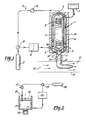
- the apparatus shown in the drawings is for use in the large scale production of ozone for purification of water for example in swimming baths, or for sewage treatment or for any other suitable purpose.
- the apparatus of Figure 1 comprises a condensation vessel 1 defining a thermally insulated chamber 2 having a gas inlet 3, a gas outlet 4 and a liquid outlet 5.
- the chamber 2 is otherwise sealed and is arranged vertically with the outlet 5 at the bottom, the outlet 4 at the top and the inlet 3 at an intermediate position.
- a helically coiled refrigeration tube 6 is mounted centrally within the chamber 2 and is connected at its upper end to an insulated reservoir 7 of liquid nitrogen.
- the vessel 1 is defined by inner and outer concentric cylindrical bodies.
- the coil 6 fits closely within the inner body and is connected at its lower end to the annular space 2 a between the bodies whereby liquid nitrogen from the reservoir 7 can flow through the coil 6 and from there, as a gas, through the space 2 a between the cylindrical bodies of the vessel 1.
- the outer cylindrical body is enclosed in suitable insulation material 1 a.
- the outlet 5 comprises a narrow vertical open-ended tube having a microporous sintered glass disc 9 (40/100 microns) fixed within the tube a short distance below its upper periphery 10.
- the bottom end 11 of the tube is connected, externally of the vessel, to a delivery pipe 12 via a stop cock 13 and/or metering device or other control.
- the outlet 5 is axially aligned with the coil 6.
- the lowermost turn of the coil 6 has a central downwardly directed kink 6 a to facilitate dripping as discussed hereinafter.
- the outlet tube 5 is connected via a hole 8 to the space 2 a between the cylindrical bodies of the vessel 1.
- the inlet 3 and the outlet 4 are connected in a circuit 14 containing an electrical ozone generator 15 of conventional form (disposed immediately before the inlet 3) and a circulation pump 16 (disposed immediately after the outlet 4).
- a supply of pure, dry oxygen, (e.g. from an oxygen cylinder 17) is connected into the circuit 14 immediately before the ozone generator 15 via a valve 18 which permits simultaneous injection of oxygen and circulation of gas through the circuit 14.
- the operation of the valve 18 is such as to permit continuous circulation of gas around the system 14 and to allow injection of fresh oxygen from the cylinder 17 only when the pressure in the system 14 falls below a predetermined value.
- the delivery pipe 12 is connected to an air feed pipe 19 which draws ambient air in through one end 20 and is connected at its other end 21 to suitable equipment (not shown) for bubbling the air through the water to be purified.
- oxygen is fed from the cylinder 17 through the ozone generator 15 to give an ozone/oxygen mixture containing about 2% ozone.
- This mixture is fed into the chamber 2 and is recirculated via the outlet 4 and the pump 16 to the generator 15.
- the coil 6 is cooled to say -160°C and ozone condenses on the coil 6 and drips down into the outlet 5 on top of the sinter plate 9.
- a layer about 1mm to 2mm thick of liquid ozone is allowed to collect on top of the sinter 9 to seal the outlet 5 relative to the external atmosphere.
- the kink 6a which is immediately above (e.g. 5mm above) the sinter 9 facilitates the deposition of drips onto the sinter 9.
- ozone is drawn off through the outlet 5 into the pipe 12. This may be achieved, after opening the stop cock 13 or other control, with reliance on gravity assisted if desired by an excess gas pressure in the chamber 2. In the latter respect it will be appreciated that a slight excess pressure can be maintained depending on the restrictive nature of the sinter 9 and can be advantageous to facilitate draw-off of ozone and also to elevate the condensation temperature of the gas. The pressure is however preferably not high enough to necessitate the use of special high pressure apparatus.
- the hole 8 feeds cool, dry nitrogen gas from the coil 6 to the underside of the sinter 9. This facilitates flushing of the liquid ozone from the sinter 9 into the pipe 12 and also helps prevent moisture passing back from the pipe 12 to the sinter 9.
- the water After treatment of the water with the ozone-containing air, the water may be passed through active charcoal to remove any excess ozone.
- the quantity of excess ozone may be monitored and used to control the proportion of ozone injected into the air stream so as to minimise wastage.
- the ozone is drawn off at the outlet 5 at a rate corresponding to the rate of condensation so that a sealing film is maintained at all times on the sinter plate 9.
- the condensation rate is determined by the rate of recirculation through the pump 16 and the proportion of injected oxygen from the cylinder 17. The latter can be adjusted as desired.
- water purification can be effected in a particularly simple, convenient and inexpensive manner.
- the air in the pipe 19 need not be specially dried before use, and the oxygen from which the ozone is produced is contained in a closed system whereby wastage of unused oxygen can be eliminated or at least appreciably reduced.
- the gas passed through the ozone generator 15 is strongly cooled due to recirculation from the chamber 2 and this can have the effect of increasing the conversion efficiency of the generator 15.
- the efficiency of the cooling arrangement is important to ensure efficient production of ozone.
- the vessel 1 should be well insulated and there should be optimum contact between the low temperature source and the gas mixture.
- the vessel 1 and coil 6 are preferably arranged to define a small circulation gap alongside the surface of the coil 6.
- a heat exchange system which uses structures different from the coil and cylindrical vessel described above.
- a refrigerant which is circulated in a closed system through the coil 6 or other heat exchange structure.
- a separate source of cool, dry nitrogen may be provided for admission into the outlet 5 to facilitate flushing of the underside of the sinter 9.
- the liquid ozone accumulates on the sinter 9 and is dispensed at a pressure which is at or slightly higher than atmospheric.
- a more highly pressurised arrangement is used.
- ozonised oxygen from an ozone generator 22 is fed to the cylinder 23 of a piston and cylinder assembly.
- the piston 24 is raised to admit the ozonised oxygen and is then forced downwardly to compress the gas mixture.
- the walls of the cylinder 23 are cooled, e.g with a jacket of liquid nitrogen or refrigerant, and liquid ozone collects on a sinter 25 in an outlet in the bottom of the cylinder 23.
- excess gas is vented via an outlet 26 in the piston 24 controlled by a pressure-relief valve 27 and is returned to the generator 22.
- Fresh oxygen is injected as necessary from a cylinder 28 via a pressure-controlled valve 29. With this arrangement a continuous forced flow of liquid ozone through the sinter 25 can be achieved.
- the dispensed ozone may be fed into water in like manner to the arrangement of Figure 1.
Landscapes
- Chemical & Material Sciences (AREA)
- Chemical Kinetics & Catalysis (AREA)
- Organic Chemistry (AREA)
- Inorganic Chemistry (AREA)
- Separation Using Semi-Permeable Membranes (AREA)
- Treatment Of Water By Oxidation Or Reduction (AREA)
- Oxygen, Ozone, And Oxides In General (AREA)
Claims (10)
- Verfahren zum Trennen einer Substanz aus einem gasförmigen Gemisch, wobei die Substanz eine höhere Kondensationstemperatur als der oder jeder andere Bestandteil des Gemisches aufweist, bei dem das gasförmige Gemisch in eine Kammer (2) mit einem unteren Ende mit einem nach unten gerichteten Flüssigkeitsauslaß (5) an diesem eingeleitet wird, wobei sich Filtermaterial innerhalb des Auslasses befindet und sich über diesen erstreckt und wobei das gasförmige Gemisch innerhalb der Kammer (2) abgekühlt wird, so daß die Substanz zu einer Flüssigkeit auf dem Filtermaterial kondensiert und dadurch den Auslaß (5) dicht verschließt, und wobei die Substanz durch das Filtermaterial abgezogen wird,
dadurch gekennzeichnet, daß das Filtermaterial eine poröse Platte (9) umfaßt, die eine der innerhalb der Kammer (2) vorhandenen Umgebung ausgesetzte obere Oberfläche sowie eine untere Oberfläche aufweist, die innerhalb des Auslasses (5) einer anderen, außerhalb der Kammer (2) vorhandenen Umgebung ausgesetzt ist, daß sich die kondensierte Flüssigkeit auf der oberen Oberfläche sammelt und eine filmartige Schicht bildet, die die Oberfläche bedeckt und den Auslaß (5) dicht abschließt, daß die Flüssigkeit von der Schicht nach unten durch die Platte (9) hindurch zu deren unteren Oberfläche hindurchdringt, wo die Flüssigkeit bei Auftreffen auf die genannte andere Umgebung verdampft, und daß die genannte Substanz abgezogen wird, während die Schicht wieder aufgefüllt wird und der dichte Abschluß durch Kondensation weiteren Materials des gasfömigen Gemisches in der Kammer (2) aufrechterhalten bleibt. - Verfahren nach Anspruch 1,
dadurch gekennzeichnet, daß das gasförmige Gemisch derart durch die Kammer zirkuliert, daß sich die kondensierte Flüssigkeit kontinuierlich bildet und auf der oberen Oberfläche ansammelt. - Verfahren nach Anspruch 1 oder 2,
dadurch gekennzeichnet, daß die Substanz an dem Auslaß kontinuierlich abgezogen wird. - Verfahren nach einem der Ansprüche 1 bis 3, bei dessen Anwendung bei der Trennung einer Substanz, die durch Behandlung eines Gases auf einer kontinuierlichen Basis mittels einer Behandlungseinrichtung gebildet wird,
dadurch gekennzeichnet, daß das gasförmige Gemisch zwischen der Kammer und der Behandlungseinrichtung zirkuliert und dabei frisches Gas nach Bedarf in das umlaufende Gemisch eingeleitet wird. - Verfahren nach einem der Ansprüche 1 bis 4,
dadurch gekennzeichnet, daß die abgezogene Substanz einem Trägergas durch dosierte Einleitung der Flüssigkeit in einen Strom des Trägergases beigemischt wird. - Verfahren nach einem der Ansprüche 1 bis 5,
dadurch gekennzeichnet, daß es sich bei der genannten Substanz um Ozon handelt. - Vorrichtung zur Verwendung bei der Durchführung des Verfahrens nach Anspruch 1, mit einer Kammer (2), die einen Einlaß (3) für ein gasförmiges Gemisch und ein unteres Ende mit einem nach unten gerichteten Flüssigkeitsauslaß (5) aufweist, in dem sich über den Auslaß erstreckendes Filtermaterial befindet, und mit einem Ursprung (6) reduzierter Temperatur, der in derartiger Verbindung mit der Kammer (2) angeordnet ist, daß er ein Kondensieren einer in dem gasförmigen Gemisch vorhandenen Substanz zu einer Flüssigkeit verursacht, die sich auf dem Filtermaterial ansammelt und den Auslaß (5) dicht abschließt,
dadurch gekennzeichnet, daß das Filtermaterial eine poröse Platte (9) umfaßt, die eine der innerhalb der Kammer (2) vorhandenen Umgebung ausgesetzte obere Oberfläche sowie eine untere Oberfläche aufweist, die innerhalb des Auslasses (5) einer anderen, außerhalb der Kammer vorhandenen Umgebung ausgesetzt ist, wodurch sich die kondensierte Flüssigkeit auf der oberen Oberfläche sammeln und dadurch eine den Auslaß (5) dicht abschließende filmartige Schicht bilden kann, und daß die poröse Platte (9) ein Abziehen der Substanz durch die Platte hindurch gestattet. - Vorrichtung nach Anspruch 7,
dadurch gekennzeichnet, daß es sich bei dem Platte (9) um eine mikroporöse gesinterte Glasscheibe handelt. - Vorrichtung nach Anspruch 7 oder 8,
dadurch gekennzeichnet, daß der Auslaß (5) unmittelbar unterhalb des Ursprungs (6) reduzierter Temperatur innerhalb der Kammer (2) angeordnet ist, so daß die kondensierte Flüssigkeit von dem genannten Ursprung direkt auf die obere Oberfläche der Platte (9) fällt. - Vorrichtung nach Anspruch 9,
dadurch gekennzeichnet, daß es sich bei dem genannten Ursprung reduzierter Temperatur um eine Rohrschlange (6) handelt, durch die ein Kühlmittel hindurchströmt.
Priority Applications (1)
| Application Number | Priority Date | Filing Date | Title |
|---|---|---|---|
| AT85302041T ATE70029T1 (de) | 1984-03-27 | 1985-03-25 | Trennung von gasfoermigen mischungen. |
Applications Claiming Priority (2)
| Application Number | Priority Date | Filing Date | Title |
|---|---|---|---|
| GB848407857A GB8407857D0 (en) | 1984-03-27 | 1984-03-27 | Separation of gaseous mixture |
| GB8407857 | 1984-03-27 |
Publications (3)
| Publication Number | Publication Date |
|---|---|
| EP0157564A2 EP0157564A2 (de) | 1985-10-09 |
| EP0157564A3 EP0157564A3 (en) | 1986-12-30 |
| EP0157564B1 true EP0157564B1 (de) | 1991-12-04 |
Family
ID=10558720
Family Applications (1)
| Application Number | Title | Priority Date | Filing Date |
|---|---|---|---|
| EP85302041A Expired - Lifetime EP0157564B1 (de) | 1984-03-27 | 1985-03-25 | Trennung von gasförmigen Mischungen |
Country Status (5)
| Country | Link |
|---|---|
| US (1) | US4666480A (de) |
| EP (1) | EP0157564B1 (de) |
| AT (1) | ATE70029T1 (de) |
| DE (1) | DE3584783D1 (de) |
| GB (2) | GB8407857D0 (de) |
Families Citing this family (24)
| Publication number | Priority date | Publication date | Assignee | Title |
|---|---|---|---|---|
| DE3628236A1 (de) * | 1986-07-17 | 1988-02-04 | Bbc Brown Boveri & Cie | Verfahren zur erzeugung eines ozon-traegergas-gemisches |
| DE3712925A1 (de) * | 1987-04-16 | 1988-11-03 | Janke & Kunkel Kg | Kuehler insbesondere fuer rotationsverdampfer |
| DE3729374C1 (de) * | 1987-09-03 | 1988-12-01 | Kernforschungsanlage Juelich | Vorrichtung zur kryogenen Anreicherung von in Gasen enthaltenen Spurenstoffen und Verwendung der Vorrichtung in einer Einrichtung |
| US5150576A (en) * | 1990-11-16 | 1992-09-29 | Liquid Carbonic Corporation | Vapor collecting apparatus |
| US8352400B2 (en) | 1991-12-23 | 2013-01-08 | Hoffberg Steven M | Adaptive pattern recognition based controller apparatus and method and human-factored interface therefore |
| US10361802B1 (en) | 1999-02-01 | 2019-07-23 | Blanding Hovenweep, Llc | Adaptive pattern recognition based control system and method |
| US5291751A (en) * | 1992-04-21 | 1994-03-08 | Liquid Carbonic Corporation | Cryo-mechanical vapor recovery apparatus |
| US5261250A (en) * | 1993-03-09 | 1993-11-16 | Polycold Systems International | Method and apparatus for recovering multicomponent vapor mixtures |
| US6080362A (en) * | 1995-06-07 | 2000-06-27 | Maxwell Technologies Systems Division, Inc. | Porous solid remediation utilizing pulsed alternating current |
| US5756054A (en) * | 1995-06-07 | 1998-05-26 | Primex Technologies Inc. | Ozone generator with enhanced output |
| DE19710581C1 (de) * | 1997-03-14 | 1998-10-01 | Testo Gmbh & Co | Kondensatabscheider mit Kondensatabführung |
| US5971368A (en) | 1997-10-29 | 1999-10-26 | Fsi International, Inc. | System to increase the quantity of dissolved gas in a liquid and to maintain the increased quantity of dissolved gas in the liquid until utilized |
| EP1051602B1 (de) * | 1997-12-12 | 2003-04-23 | Medi-Physics, Inc. | Verfahren zum sägen und auftauen eines xenon enthaltenden polarisierten gases |
| US6235641B1 (en) | 1998-10-30 | 2001-05-22 | Fsi International Inc. | Method and system to control the concentration of dissolved gas in a liquid |
| US7966078B2 (en) | 1999-02-01 | 2011-06-21 | Steven Hoffberg | Network media appliance system and method |
| US6406551B1 (en) | 1999-05-14 | 2002-06-18 | Fsi International, Inc. | Method for treating a substrate with heat sensitive agents |
| US6274506B1 (en) | 1999-05-14 | 2001-08-14 | Fsi International, Inc. | Apparatus and method for dispensing processing fluid toward a substrate surface |
| US6212904B1 (en) * | 1999-11-01 | 2001-04-10 | In-X Corporation | Liquid oxygen production |
| KR200211673Y1 (ko) * | 2000-08-18 | 2001-01-15 | 김세함 | 오존수 제조장치 |
| US7210312B2 (en) * | 2004-08-03 | 2007-05-01 | Sunpower, Inc. | Energy efficient, inexpensive extraction of oxygen from ambient air for portable and home use |
| WO2008004278A1 (fr) | 2006-07-04 | 2008-01-10 | Toshiba Mitsubishi-Electric Industrial Systems Corporation | Procédé et dispositif de concentration / dilution de gaz spécifique |
| US7802423B2 (en) * | 2006-08-21 | 2010-09-28 | General Electric Company | Condenser unit for NOx emission reduction system |
| CN109200737B (zh) * | 2017-07-04 | 2024-04-26 | 保定赛印科学仪器研发有限公司 | 臭氧提纯装置和臭氧提纯系统 |
| WO2024262393A1 (ja) * | 2023-06-21 | 2024-12-26 | エコデザイン株式会社 | オゾン含有気液二相流生成装置、オゾン含有溶液製造装置、オゾン含有気体製造装置、オゾン含有気液二相流生成方法、オゾン含有溶液製造方法、オゾン含有気体製造方法 |
Citations (1)
| Publication number | Priority date | Publication date | Assignee | Title |
|---|---|---|---|---|
| US3921002A (en) * | 1974-04-22 | 1975-11-18 | Martin Marietta Corp | Ozone generator |
Family Cites Families (12)
| Publication number | Priority date | Publication date | Assignee | Title |
|---|---|---|---|---|
| GB195598A (en) * | 1922-03-30 | 1923-12-06 | Air Liquide | Improvements in or relating to the preliminary treatment or purification of illuminating or coal gas or coke oven gases intended for the recovery of hydrogen by partial liquefaction |
| NL22102C (de) * | 1926-06-15 | |||
| US2704274A (en) * | 1946-10-25 | 1955-03-15 | Robert W Fulwider | Apparatus and method for producing liquid ozone |
| US2864757A (en) * | 1956-02-17 | 1958-12-16 | Air Reduction | Ozone concentration and dilution |
| US3415069A (en) * | 1966-10-31 | 1968-12-10 | Nasa | High pressure helium purifier |
| US3396515A (en) * | 1967-03-23 | 1968-08-13 | Neal A. Wright | Air dryer |
| JPS5334693A (en) * | 1976-09-13 | 1978-03-31 | Osaka Gas Co Ltd | Ozone generating apparatus |
| DE2659702C3 (de) * | 1976-12-31 | 1981-08-13 | Daido Sanso K.K., Osaka | Verfahren zur Massenproduktion von Ozon |
| JPS5465163A (en) * | 1977-11-02 | 1979-05-25 | Seitai Kagaku Kenkyusho Kk | Super cooling type gas trapping apparatus |
| US4242111A (en) * | 1979-03-16 | 1980-12-30 | Andrew Arends | Compressed air dryer |
| JPS5714234A (en) * | 1980-06-30 | 1982-01-25 | Kohan Denshi Kogyo Kk | Power supplying method for information data transmitter and receiver or the like |
| FR2545588B1 (fr) * | 1983-05-05 | 1985-10-11 | Air Liquide | Appareil de refrigeration et piege frigorifique comprenant un tel appareil |
-
1984
- 1984-03-27 GB GB848407857A patent/GB8407857D0/en active Pending
-
1985
- 1985-03-22 GB GB08507556A patent/GB2156237B/en not_active Expired
- 1985-03-25 DE DE8585302041T patent/DE3584783D1/de not_active Expired - Fee Related
- 1985-03-25 EP EP85302041A patent/EP0157564B1/de not_active Expired - Lifetime
- 1985-03-25 AT AT85302041T patent/ATE70029T1/de not_active IP Right Cessation
- 1985-03-26 US US06/716,124 patent/US4666480A/en not_active Expired - Fee Related
Patent Citations (1)
| Publication number | Priority date | Publication date | Assignee | Title |
|---|---|---|---|---|
| US3921002A (en) * | 1974-04-22 | 1975-11-18 | Martin Marietta Corp | Ozone generator |
Non-Patent Citations (1)
| Title |
|---|
| Organikum (organisch-chemisches Grundpraktikum) VEB-Deutscher Verlag der Wissenschaften, Berlin 1963 * |
Also Published As
| Publication number | Publication date |
|---|---|
| GB2156237B (en) | 1987-09-03 |
| GB8507556D0 (en) | 1985-05-01 |
| ATE70029T1 (de) | 1991-12-15 |
| GB8407857D0 (en) | 1984-05-02 |
| EP0157564A2 (de) | 1985-10-09 |
| GB2156237A (en) | 1985-10-09 |
| US4666480A (en) | 1987-05-19 |
| DE3584783D1 (de) | 1992-01-16 |
| EP0157564A3 (en) | 1986-12-30 |
Similar Documents
| Publication | Publication Date | Title |
|---|---|---|
| EP0157564B1 (de) | Trennung von gasförmigen Mischungen | |
| US6153150A (en) | Apparatus and method for controlled decomposition oxidation of gaseous pollutants | |
| US3649467A (en) | Vaporization apparatus for the removal of heat and concentration of electrolyte in a fuel cell battery | |
| EP0284052B1 (de) | Verfahren zur Erzeugung hochreinen Wassers und Verfahren zur Verwendung dieses Wassers | |
| EP0808916B1 (de) | Verdampfungsapparat | |
| US5180403A (en) | Method for vacuum deaeration | |
| EP0226216A2 (de) | Destilliervorrichtung | |
| US4462965A (en) | Intermittent ozonizing apparatus | |
| CA1162476A (en) | Method and apparatus for enriching liquids with gases | |
| US5286468A (en) | Producing carbon-14 isotope from spent resin waste | |
| US4869785A (en) | Steam distillation apparatus | |
| CN1127652C (zh) | 从低温空气分离装置回收和纯化氩的方法和设备 | |
| US5468350A (en) | Apparatus for manufacturing ultrapure water | |
| WO2001066236A2 (en) | Pervaporation apparatus and method | |
| CA1039358A (en) | Coulometric detector | |
| CN206051561U (zh) | 一种超纯二氧化碳生产系统 | |
| US3215504A (en) | Plate tower | |
| US3308606A (en) | Method of drying moisture bearing chlorine gas | |
| US20150040843A1 (en) | Water vapor management and control methodology system for single and multiple hydrogen fuel cells used for combustion augmentation in internal combustion engines and method | |
| JP2003130988A (ja) | 酸素濃度管理装置 | |
| US574111A (en) | Process of and apparatus | |
| JPH11262782A (ja) | 高濃度オゾン水製造装置 | |
| KR20250105714A (ko) | 가스 크로마토그래프 및 수소 발생용 집합체를 갖는 가스 크로마토그래픽 시스템 | |
| CN209645881U (zh) | 一种高效填料精馏塔 | |
| US4078894A (en) | Analyzer system with salt extractor |
Legal Events
| Date | Code | Title | Description |
|---|---|---|---|
| PUAI | Public reference made under article 153(3) epc to a published international application that has entered the european phase |
Free format text: ORIGINAL CODE: 0009012 |
|
| AK | Designated contracting states |
Designated state(s): AT BE CH DE FR IT LI NL SE |
|
| PUAL | Search report despatched |
Free format text: ORIGINAL CODE: 0009013 |
|
| AK | Designated contracting states |
Kind code of ref document: A3 Designated state(s): AT BE CH DE FR IT LI NL SE |
|
| 17P | Request for examination filed |
Effective date: 19870630 |
|
| 17Q | First examination report despatched |
Effective date: 19880803 |
|
| GRAA | (expected) grant |
Free format text: ORIGINAL CODE: 0009210 |
|
| AK | Designated contracting states |
Kind code of ref document: B1 Designated state(s): AT BE CH DE FR IT LI NL SE |
|
| PG25 | Lapsed in a contracting state [announced via postgrant information from national office to epo] |
Ref country code: SE Effective date: 19911204 Ref country code: NL Effective date: 19911204 Ref country code: IT Free format text: LAPSE BECAUSE OF FAILURE TO SUBMIT A TRANSLATION OF THE DESCRIPTION OR TO PAY THE FEE WITHIN THE PRESCRIBED TIME-LIMIT;WARNING: LAPSES OF ITALIAN PATENTS WITH EFFECTIVE DATE BEFORE 2007 MAY HAVE OCCURRED AT ANY TIME BEFORE 2007. THE CORRECT EFFECTIVE DATE MAY BE DIFFERENT FROM THE ONE RECORDED. Effective date: 19911204 Ref country code: BE Effective date: 19911204 Ref country code: AT Effective date: 19911204 |
|
| REF | Corresponds to: |
Ref document number: 70029 Country of ref document: AT Date of ref document: 19911215 Kind code of ref document: T |
|
| REF | Corresponds to: |
Ref document number: 3584783 Country of ref document: DE Date of ref document: 19920116 |
|
| ET | Fr: translation filed | ||
| NLV1 | Nl: lapsed or annulled due to failure to fulfill the requirements of art. 29p and 29m of the patents act | ||
| PLBE | No opposition filed within time limit |
Free format text: ORIGINAL CODE: 0009261 |
|
| STAA | Information on the status of an ep patent application or granted ep patent |
Free format text: STATUS: NO OPPOSITION FILED WITHIN TIME LIMIT |
|
| 26N | No opposition filed | ||
| PGFP | Annual fee paid to national office [announced via postgrant information from national office to epo] |
Ref country code: CH Payment date: 19930326 Year of fee payment: 9 |
|
| PGFP | Annual fee paid to national office [announced via postgrant information from national office to epo] |
Ref country code: FR Payment date: 19930329 Year of fee payment: 9 |
|
| PGFP | Annual fee paid to national office [announced via postgrant information from national office to epo] |
Ref country code: DE Payment date: 19930525 Year of fee payment: 9 |
|
| PG25 | Lapsed in a contracting state [announced via postgrant information from national office to epo] |
Ref country code: LI Effective date: 19940331 Ref country code: CH Effective date: 19940331 |
|
| PG25 | Lapsed in a contracting state [announced via postgrant information from national office to epo] |
Ref country code: FR Effective date: 19941130 |
|
| REG | Reference to a national code |
Ref country code: CH Ref legal event code: PL |
|
| PG25 | Lapsed in a contracting state [announced via postgrant information from national office to epo] |
Ref country code: DE Effective date: 19941201 |
|
| REG | Reference to a national code |
Ref country code: FR Ref legal event code: ST |