EP0157216B1 - Magnetic apparatus - Google Patents
Magnetic apparatus Download PDFInfo
- Publication number
- EP0157216B1 EP0157216B1 EP85102608A EP85102608A EP0157216B1 EP 0157216 B1 EP0157216 B1 EP 0157216B1 EP 85102608 A EP85102608 A EP 85102608A EP 85102608 A EP85102608 A EP 85102608A EP 0157216 B1 EP0157216 B1 EP 0157216B1
- Authority
- EP
- European Patent Office
- Prior art keywords
- magnetic
- soft magnetic
- microwave device
- plates
- composition
- Prior art date
- Legal status (The legal status is an assumption and is not a legal conclusion. Google has not performed a legal analysis and makes no representation as to the accuracy of the status listed.)
- Expired
Links
Images


Classifications
-
- H—ELECTRICITY
- H01—ELECTRIC ELEMENTS
- H01P—WAVEGUIDES; RESONATORS, LINES, OR OTHER DEVICES OF THE WAVEGUIDE TYPE
- H01P1/00—Auxiliary devices
- H01P1/20—Frequency-selective devices, e.g. filters
- H01P1/215—Frequency-selective devices, e.g. filters using ferromagnetic material
- H01P1/218—Frequency-selective devices, e.g. filters using ferromagnetic material the ferromagnetic material acting as a frequency selective coupling element, e.g. YIG-filters
-
- H—ELECTRICITY
- H01—ELECTRIC ELEMENTS
- H01F—MAGNETS; INDUCTANCES; TRANSFORMERS; SELECTION OF MATERIALS FOR THEIR MAGNETIC PROPERTIES
- H01F7/00—Magnets
- H01F7/02—Permanent magnets [PM]
Definitions
- the present invention relates to a magnetic apparatus such as, for example, a microwave filter, including a microwave device, e.g., ferromagnetic resonator, formed of yttrium iron garnet (VIG) and operated in a d.c. bias magnetic field.
- a microwave filter including a microwave device, e.g., ferromagnetic resonator, formed of yttrium iron garnet (VIG) and operated in a d.c. bias magnetic field.
- a ferromagnetic resonator e.g., a device using ferrimagnetic resonance of an YIG thin film device, has its resonance frequency dependent on the saturation magnetization of the device, and therfore the resonance frequency is directly affected by the temperature characteristics of the saturation magnetization.
- the YIG thin film device In order for the YIG thin film device to have a constant resonance frequency (fo) of perpendicular resonance independently of the temperature (T), the device needs to be placed in a thermostatic chamber so that the device itself is kept at a constant temperature, or biased by an offset magnetic field proportional to the temperature dependent variation of YIG saturation magnetization 4nM s (10- 4 T), in addition to the application of a constant d.c. magnetic field which determines the resonance frequency fo.
- the magnetic field strength Hg in an air gap where an YIG device is placed is given as follows.
- Nzy is the demagnetization factor of YIG
- y is the gyromagnetic ratio.
- the gap magnetic field Hg is designed to have the temperature characteristics in proportion to the temperature characteristics of a ferromagnetic resonator device, e.g., an YIG device, by the superimposition of the temperature characteristics of the permanent magnet and the temperature characteristics of magnetization of the soft magnetic plate so as to compensate the temperature dependency of the resonance frequency fo of the device, whereby fo can be made constant in a wide temperature range.
- a ferromagnetic resonator device e.g., an YIG device
- Fig. 1 Illustrated in Fig. 1 is a magnetic circuit consisting of a "C"-shaped yoke 1, which is provided at its confronting end sections with pairs of a permanent magnet 2 and a soft magnetic plate 3 made of, for example, ferrite or alloy, and an air gap 4 with a spacing of I g formed between the soft magnetic plates 3.
- 1 m represents the total thickness of the magnet 2
- I x is the total thickness of the soft magnetic plates 3
- B m and H m are the magnetic flux density and magnetic field strength in each magnet 2
- B x and H are the magnetic flux density and magnetic field strength in each of the soft magnetic plates
- Bg and Hg are the magnetic flux density and magnetic field strength in the air gap 4.
- the permanent magnets 2 are situated in a demagnetizing field, and thus the magnetic field strength H m points oppositely to the magnetic flux density B m .
- the CGS unit system is used throughout the following discussion.
- Equations (2) and (3) are reduced to as follows.
- the internal magnetic field H x of the soft magnetic plate is given as follows.
- the term 4 ⁇ M x in Equation (6) is replaced with the saturation magnetization 4 ⁇ M sx .
- Equation (6) the gap magnetic field Hg is expressed as follows.
- the gap magnetic fild Hg is expressed as a function of the temperature T in terms of the internal magnetic field strength H m (T) and the magnetization strength 4nM sx (T) of the soft magnetic plate both at a temperature of T, as follows.
- the characteristics of the soft magnetic plate are adjusted in such a way of, for example, choosing the composition and sintering condition of ferrite, choosing the composition of alloy, or using several kinds of soft magnetic plates in combination.
- the selection of the composition and processing condition for the soft magnetic plate it is extremely difficult to model the Hg on the desired temperature characteristics of the ferromagnetic resonator device inclusive of slope and curvature of the plot.
- a magnetic apparatus similar to the apparatus as described above is known from US-A-3,681,716.
- the soft magnetic plates are mild steel wavers.
- the apparatus as described above is modified in such a way, that both magnetic plates sandwiching the microwave device are made of a magnetic material having a composition substantially identical to the composition of said microwave device, and that the ratio of the thickness of said soft magnetic plates to the gap length is selected to minimize the temperature dependency of the frequency characteristic.
- each of the soft magnetic plates sandwiching the microwave device is made of two subplates, whereby one of the subplates is made of the magnetic material having a composition substantially identical to the composition of said microwave device and the thicknesses of the both subplates are selected to minimize temperature dependency of the frequency characteristic.
- the present invention resides in a magnetic apparatus including a microwave device which operates in the d.c. bias magnetic field, wherein a magnetic circuit for producing the d.c. bias magnetic field is constructed by incorporating a soft magnetic plate formed of a material of the substantially same composition, or preferably the exactly same composition, as that of the microwave device so that the magnetic circuit has the similar or equal temperature characteristics as of the microwave device.
- the arrangement includes a yoke 11 having four sides, with its confronting two sides being provided thereon each with a magnet 12, which is further overlaid with the first and/or second soft magnetic plates 13 and 14 in different composition from each other.
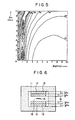
- the arrangement of Fig. 2 includes a pair of the first and second soft magnetic plates 13 and 14 affixed to the magnet 12 of each side so that an air gap 15 is formed between the plates on both sides, while the arrangement of Fig. 3 includes the first soft magnetic plate 13 affixed to the magnet 12 on one side and the second plate 14 on another side, with an air gap 15 formed between both soft magnetic plates.
- a microwave device 16 e.g., an YIG ferrimagnetic resonator device.
- At least one of the soft magnetic plates, e.g., the first plate 13, is formed of a material with the substantially same composition as of the microwave device 16, e.g., an YIG plate of the same composition, and another soft magnetic plate, e.g., the second plate 14, is formed of other magnetic material, e.g., a ferrite plate.
- the first soft magnetic plate 13 is formed of YIG and the second soft magnetic plate 14 is formed of Mg-Mn-AI ferrite.
- Fig. 4 shows the frequency variation Af ( ⁇ MHz) from fo plotted on a plane of the thickness I x1 (vertical axis) and I x2 (horizontal axis) of the first and second soft magnetic plates 13 and 14 and linked to form contour lines, with the ambient temperature varied in the range from -20°C to +60°C.
- Numerals indicating each contour line in the figure represent the absolute values of frequency variation in MHz.
- the arrangement using two kinds of soft magnetic plates is capable of much alleviating the temperature dependency of the resonance frquency as compared with the structure using soft magnetic plates solely made of ferrite as shown in Fig. 1.
- Table 1 lists the measure of the thickness of I m of the magnet, thickness I X1 of YIG plate, thickness I x2 of ferrite plate, and frequency variation ⁇ f.
- Fig. 5 shows the contour lines of Af on the plane of the thickness I x1 and I x2 of the first and second soft magnetic planes 13 and 14.
- the resonance frequency can be less temperature dependent through the construction of the soft magnetic plate using the same material as of the microwave device 16, e.g., YIG, and this point will further be explained in the following.
- Equation (10) is reduced to as follows.
- Equation (11) In order for both sides of Equation (11) to be equal invariably, they need to have equal constant terms and equal temperature-dependent terms as follows.
- Equation (13) is reduced to as follows.
- Equation (15) is reduced to as follows.
- the soft magnetic plate which equalizes the right sides of Equations (1) and (8) is YIG, the material of the magnetic device itself.
- the apparatus can have an extremely improved temperature characteristics by using YIG, the material of the magnetic device, for forming the soft magnetic plate when the permanent magnet has a certain temperature coefficient ⁇ .
- Equation (22) For a given permanent magnet having linear temperature characteristics and a temperature coefficient of ⁇ , dimensions are chosen to be so that Equation (22) is satisfied, and at the same time dimensions are adjusted depending on the field strength H mo of the permanent magnet to meet the following.
- the gap magnetic field H g (T) becomes as follows.
- Af is the deviation of a 4nM s y(T) from the linear approximation compressed by I g /(I g + I x ) and further multiplied by y, and it can be made extremely small.
- magnetization obtained from linear approximation is 1918.5.10-4 T at -20°C as against the measured value 1915.8, merely leaving a small difference of 2.7 10- 4 T, and at +60°C the measured value is 1622.1 ⁇ 10 -4 T, while linear approximation gives 1625.1 ⁇ 10 -4 T with a small deviation of 3.0 ⁇ 10 -4 T.
- a filter element made up of a micro-strip line and a ferrimagnetic resonator device in a certain formation on a dielectric substrate is to be placed in the filter gap 15, although the arrangement is not shown.
- the soft magnetic plate is formed of one or two kinds of material, it can be formed using three or more kinds of material.
- the present invention can also be applied to any magnetic apparatus employing a resonator of other material, or other than a resonator but other type of magnetic device, e.g., a magnetoresistance effect device, operated in the d.c. magnetic field produced by a magnetic circuit.
- a magnetoresistance effect device operated in the d.c. magnetic field produced by a magnetic circuit.
- a magnetic circuit for producing a d.c. bias magnetic field is constructed to include in its part a soft magnetic plate of the same material as of the microwave device whereby the d.c. magnetic field is accurately and easily compensated against the temperature variation to a precise extent of modelling the curvature of the temperature characteristics.
- the present invention can advantageously be applied to various magnetic apparatus such as microwave filters.
Description
- The present invention relates to a magnetic apparatus such as, for example, a microwave filter, including a microwave device, e.g., ferromagnetic resonator, formed of yttrium iron garnet (VIG) and operated in a d.c. bias magnetic field.
- A ferromagnetic resonator, e.g., a device using ferrimagnetic resonance of an YIG thin film device, has its resonance frequency dependent on the saturation magnetization of the device, and therfore the resonance frequency is directly affected by the temperature characteristics of the saturation magnetization. In order for the YIG thin film device to have a constant resonance frequency (fo) of perpendicular resonance independently of the temperature (T), the device needs to be placed in a thermostatic chamber so that the device itself is kept at a constant temperature, or biased by an offset magnetic field proportional to the temperature dependent variation of YIG saturation magnetization 4nMs (10-4 T), in addition to the application of a constant d.c. magnetic field which determines the resonance frequency fo.
- Suppose in a magnetic circuit, the magnetic field strength Hg in an air gap where an YIG device is placed is given as follows.

- However, either of the case of using an electromagnet and the previous case of using a thermostatic chamber needs the supply of energy such as a controlled current from the outside, resulting in a complex structure. According to one method of controlling the temperature characteristics of the gap magnetic field Hg with a soft magnetic plate, the gap magnetic field Hg is designed to have the temperature characteristics in proportion to the temperature characteristics of a ferromagnetic resonator device, e.g., an YIG device, by the superimposition of the temperature characteristics of the permanent magnet and the temperature characteristics of magnetization of the soft magnetic plate so as to compensate the temperature dependency of the resonance frequency fo of the device, whereby fo can be made constant in a wide temperature range.
- Illustrated in Fig. 1 is a magnetic circuit consisting of a "C"-
shaped yoke 1, which is provided at its confronting end sections with pairs of apermanent magnet 2 and a softmagnetic plate 3 made of, for example, ferrite or alloy, and anair gap 4 with a spacing of Ig formed between the softmagnetic plates 3. In the figure, 1m represents the total thickness of themagnet 2, Ix is the total thickness of the softmagnetic plates 3, Bm and Hm are the magnetic flux density and magnetic field strength in eachmagnet 2, Bx and H, are the magnetic flux density and magnetic field strength in each of the softmagnetic plates 3, and Bg and Hg are the magnetic flux density and magnetic field strength in theair gap 4. Thepermanent magnets 2 are situated in a demagnetizing field, and thus the magnetic field strength Hm points oppositely to the magnetic flux density Bm. The CGS unit system is used throughout the following discussion. - The Maxwell's equations for the above-mentioned magnetic circuit are expressed in terms of the magnetic flux density and the magnetic field as follows.

- On the assumption that the magnetic field and magnetic flux density are uniform in the magnet and soft magnetic plates and there is no magnetic flux leakage to the outside of the circuit, Equations (2) and (3) are reduced to as follows.


- Provided the magnetization of the soft magnetic plate to be 4πMx, the internal magnetic field Hx of the soft magnetic plate is given as follows.


- Substituting Equation (6) into (5), the gap magnetic field Hg is expressed as follows.

- Accordingly, the gap magnetic fild Hg is expressed as a function of the temperature T in terms of the internal magnetic field strength Hm(T) and the magnetization strength 4nMsx(T) of the soft magnetic plate both at a temperature of T, as follows.

- Accordingly, by choosing the characteristics and dimensions of the
magnets 2 and softmagnetic plates 3 and the length of the gap, i.e., Hm, 4πMsx, Nzx, 1m, Ix, and I9, an optimum Hg can be obtained from Equation (9). - In practice, the characteristics of the soft magnetic plate are adjusted in such a way of, for example, choosing the composition and sintering condition of ferrite, choosing the composition of alloy, or using several kinds of soft magnetic plates in combination. However, even by the selection of the composition and processing condition for the soft magnetic plate, it is extremely difficult to model the Hg on the desired temperature characteristics of the ferromagnetic resonator device inclusive of slope and curvature of the plot. On this account, it has not been feasible to maintain constant the resonance frequency fo of a ferrimagnetic resonator device, e.g., YIG device, over a wide temperature range.
- A magnetic apparatus similar to the apparatus as described above is known from US-A-3,681,716. In the apparatus of the US-patent, the soft magnetic plates are mild steel wavers.
- It is the object of the present invention to provide the magnetic apparatus having a microwave device with minimized temperature dependency of the frequency characteristic.
- According to one aspect of the present invention, the apparatus as described above is modified in such a way, that both magnetic plates sandwiching the microwave device are made of a magnetic material having a composition substantially identical to the composition of said microwave device, and that the ratio of the thickness of said soft magnetic plates to the gap length is selected to minimize the temperature dependency of the frequency characteristic.
- According to another aspect of the present invention, the apparatus as described above is modified in such a way that each of the soft magnetic plates sandwiching the microwave device is made of two subplates, whereby one of the subplates is made of the magnetic material having a composition substantially identical to the composition of said microwave device and the thicknesses of the both subplates are selected to minimize temperature dependency of the frequency characteristic.
-
- Fig. 1 is an illustration showing schematically the structure of the conventional magnetic apparatus;
- Figs. 2, 3 and 6 are schematic illustrations showing structures of the magnetic apparatus according to the present invention;
- Figs. 4 and 5 are graphical representations each showing the relationship between the dimensions of the soft magnetic plate and the variation in the resonance frequency dependent on the temperature, and
- Figs. 7 and 8 are graphs used to explain the characteristics of the apparatus according to the present invention.
- The present invention resides in a magnetic apparatus including a microwave device which operates in the d.c. bias magnetic field, wherein a magnetic circuit for producing the d.c. bias magnetic field is constructed by incorporating a soft magnetic plate formed of a material of the substantially same composition, or preferably the exactly same composition, as that of the microwave device so that the magnetic circuit has the similar or equal temperature characteristics as of the microwave device.
- In Figs. 2 and 3 showing embodiments of this invention, the arrangement includes a
yoke 11 having four sides, with its confronting two sides being provided thereon each with amagnet 12, which is further overlaid with the first and/or second softmagnetic plates magnetic plates magnet 12 of each side so that anair gap 15 is formed between the plates on both sides, while the arrangement of Fig. 3 includes the first softmagnetic plate 13 affixed to themagnet 12 on one side and thesecond plate 14 on another side, with anair gap 15 formed between both soft magnetic plates. Placed in theair gap 15 is amicrowave device 16, e.g., an YIG ferrimagnetic resonator device. At least one of the soft magnetic plates, e.g., thefirst plate 13, is formed of a material with the substantially same composition as of themicrowave device 16, e.g., an YIG plate of the same composition, and another soft magnetic plate, e.g., thesecond plate 14, is formed of other magnetic material, e.g., a ferrite plate. - In accordance with the basic structure shown in Fig. 3, the first soft
magnetic plate 13 is formed of YIG and the second softmagnetic plate 14 is formed of Mg-Mn-AI ferrite. A permanent magnet made of SmCo5 in a 30 mm diameter (with residual magnetic flux density Br = 8134·10-4T, coercive force HC = 7876 Gb/cm, temperature coefficient a = -0.0005, and with expotential temperature characteristics) is used for themagnet 12. An YIG disk with a 2 mm diameter and a 20 pm thickness is used for themagnetic device 16, and it is placed in theair gap 15 with a gap length Ig = 2 mm. The thickness Im of themagnet 12 is chosen so that thedevice 16 resonates at a resonance frequency fo = 3 GHz. - Fig. 4 shows the frequency variation Af (±MHz) from fo plotted on a plane of the thickness Ix1 (vertical axis) and Ix2 (horizontal axis) of the first and second soft
magnetic plates 
- This embodiment has the same structure as of the previous embodiment, except for the
permanent magnet 12 which is in this case made of CeCos (with Br = 6250·10-4T G, Hc = 6250 Gb/cm, a = -0.0009, and with linear temperature characteristics). - Fig. 5 shows the contour lines of Af on the plane of the thickness Ix1 and Ix2 of the first and second soft
magnetic planes magnet 3 with a = -0.0009 as compared with the case with a = -0.0005 ofEmbodiment 1. - This embodiment employs a
permanent magnet 12 of a = -0.001 (with Br = 6300·10-4T, He = 5500 Gb/cm, and with linear temperature characteristics), and uses merely the first softmgnetic plates 13 of YIG as shown in Fig. 6. As a result, Δf = ±2.224 MHz was achieved for Im = 3.281 mm, Ix1 = 3.857 mm. - Namely, according as the temperature coefficient a of the
permanent magnet 12 approaches the average -0.00128 obtained from Equation (1), it becomes feasible to implement the reduction of Af, i.e., the temperature dependency of the resonance frequency, through the sole use of the YIG plate. Nevertheless, it is also possible to reduce the Af in the case of using two kinds of soft magnetic plates by using the same material as of the microwave device for one plate. - As mentioned above, the resonance frequency can be less temperature dependent through the construction of the soft magnetic plate using the same material as of the
microwave device 16, e.g., YIG, and this point will further be explained in the following. - As an idealized condition, the temperature dependency of the resonance frequency is nullified when the right side of Equations (1) and (9) is equal, namely

- Assuming the permanent magnet to have an extremely small temperature coefficient and the Hm(t) has a constant value Hmo, Equation (10) is reduced to as follows.

- In order for both sides of Equation (11) to be equal invariably, they need to have equal constant terms and equal temperature-dependent terms as follows.


- Equation (12) gives

- Assuming that the YIG device and soft magnetic plate are both thin enough and the Nzy and Nzx are substantially equal to 1, Equation (13) is reduced to as follows.

- On the further assumption that Ig « Ix, the constant part


- Accordingly, on the assumption that the
permanent magnet 13 has constant characteristics independent of the temperature and theair gap 15 has a sufficiently small gap length I9, the soft magnetic plate which equalizes the right sides of Equations (1) and (8) is YIG, the material of the magnetic device itself. - The following indicates the fact that the apparatus can have an extremely improved temperature characteristics by using YIG, the material of the magnetic device, for forming the soft magnetic plate when the permanent magnet has a certain temperature coefficient β.
- Solving the above Equation (10), which is derived by equating the above Equations (1) and (9), for Hm(T) on the assumption of Nzx = Nzy ÷ 1 gives

- Linear approximation for the temperature characteristics of YIG saturation magnetization using an average temperature coefficient a in a temperature range between T1 and T2 concerned as shown in Fig. 7 gives

- Substituting Equation (18) into (17) gives

- This equation is expressed as follows.


- For a given permanent magnet having linear temperature characteristics and a temperature coefficient of β, dimensions are chosen to be


- Then, the gap magnetic field Hg(T) becomes as follows.

- The resonance frequency f is given, when Nzy = 1, as

- The variation of resonance frequency, Af = f - fo, is obtained from Equations (25) and (26) as follows.

- Namely, Af is the deviation of a 4nMsy(T) from the linear approximation compressed by Ig/(Ig + Ix) and further multiplied by y, and it can be made extremely small. For example, as shown in Fig. 8, magnetization obtained from linear approximation is 1918.5.10-4 T at -20°C as against the measured value 1915.8, merely leaving a small difference of 2.7 10-4 T, and at +60°C the measured value is 1622.1·10-4 T, while linear approximation gives 1625.1 · 10-4 T with a small deviation of 3.0·10-4 T.
- By setting Ig/(Ig + Ix) = 0.2 and y = 2.8, the resonance frequency variation becomes Af = 2.8 x 0.2 x 3.0 = 1.68 MHz, or as small as Af = ± 0.84 MHz.
- It is thus appreciated that the use of a soft magnetic plate made of YIG provides a magnetic apparatus with extraordinary uniform temperature characteristics, i.e., the resonance frequency with its temperature dependency well compensated.
- In practice, when the present invention is applied to a microwave filter for example, a filter element made up of a micro-strip line and a ferrimagnetic resonator device in a certain formation on a dielectric substrate is to be placed in the
filter gap 15, although the arrangement is not shown. - Although in the foregoing embodiments the soft magnetic plate is formed of one or two kinds of material, it can be formed using three or more kinds of material.
- Although the foregoing embodiments have been described for the case of YIG ferromagnetic resonator as a microwave device, the present invention can also be applied to any magnetic apparatus employing a resonator of other material, or other than a resonator but other type of magnetic device, e.g., a magnetoresistance effect device, operated in the d.c. magnetic field produced by a magnetic circuit.
- According to the present invention, as described above, a magnetic circuit for producing a d.c. bias magnetic field is constructed to include in its part a soft magnetic plate of the same material as of the microwave device whereby the d.c. magnetic field is accurately and easily compensated against the temperature variation to a precise extent of modelling the curvature of the temperature characteristics. Moreover, by using combined materials, for example, one for the coarse adjustment to model the slope of the temperature characteristics, the other for the fine adjustment to model the curvature of the temperature characteristics the temperature compensation can be accomplished more accurately and easily. Accordingly, the present invention can advantageously be applied to various magnetic apparatus such as microwave filters.
Claims (3)
characterized in that
Applications Claiming Priority (2)
| Application Number | Priority Date | Filing Date | Title |
|---|---|---|---|
| JP59044244A JPS60189205A (en) | 1984-03-08 | 1984-03-08 | Magnetic equipment |
| JP44244/84 | 1984-03-08 |
Publications (2)
| Publication Number | Publication Date |
|---|---|
| EP0157216A1 EP0157216A1 (en) | 1985-10-09 |
| EP0157216B1 true EP0157216B1 (en) | 1990-11-14 |
Family
ID=12686119
Family Applications (1)
| Application Number | Title | Priority Date | Filing Date |
|---|---|---|---|
| EP85102608A Expired EP0157216B1 (en) | 1984-03-08 | 1985-03-07 | Magnetic apparatus |
Country Status (5)
| Country | Link |
|---|---|
| US (1) | US4701729A (en) |
| EP (1) | EP0157216B1 (en) |
| JP (1) | JPS60189205A (en) |
| CA (1) | CA1232039A (en) |
| DE (1) | DE3580504D1 (en) |
Families Citing this family (8)
| Publication number | Priority date | Publication date | Assignee | Title |
|---|---|---|---|---|
| CA1266100A (en) * | 1985-07-09 | 1990-02-20 | Seigo Ito | Yig thin film microwave apparatus |
| JPS6384301A (en) * | 1986-09-29 | 1988-04-14 | Sony Corp | Ferromagnetic resonance equipment |
| JPS63103501A (en) * | 1986-10-20 | 1988-05-09 | Sony Corp | Ferromagnetic resonator |
| JPH01152802A (en) * | 1987-12-10 | 1989-06-15 | Sony Corp | Ferrimagnetic resonator |
| DE3834984A1 (en) * | 1988-10-14 | 1990-04-19 | Leybold Ag | DEVICE FOR GENERATING ELECTRICALLY CHARGED AND / OR UNCHARGED PARTICLES |
| US5677652A (en) * | 1996-04-24 | 1997-10-14 | Verticom, Inc. | Microwave ferrite resonator with parallel permanent magnet bias |
| US6201449B1 (en) * | 1999-07-24 | 2001-03-13 | Stellex Microwave Systems, Inc. | Ferromagnetic tuning ring for YIG oscillators |
| CN109270106B (en) * | 2017-07-18 | 2020-09-22 | 中电海康集团有限公司 | Method for measuring magnetic uniformity of magnetic ultrathin film and application thereof |
Family Cites Families (10)
| Publication number | Priority date | Publication date | Assignee | Title |
|---|---|---|---|---|
| US3016497A (en) * | 1959-12-08 | 1962-01-09 | Bell Telephone Labor Inc | Nonreciprocal electromagnetic device |
| FR2050584A5 (en) * | 1969-06-18 | 1971-04-02 | Lignes Telegraph Telephon | |
| US3740675A (en) * | 1970-08-17 | 1973-06-19 | Westinghouse Electric Corp | Yig filter having a single substrate with all transmission line means located on a common surface thereof |
| US4096461A (en) * | 1974-08-23 | 1978-06-20 | U.S. Philips Corporation | Magnet system for tunable YIG oscillator and tunable YIG filter |
| US4020429A (en) * | 1976-02-12 | 1977-04-26 | Motorola, Inc. | High power radio frequency tunable circuits |
| US4152676A (en) * | 1977-01-24 | 1979-05-01 | Massachusetts Institute Of Technology | Electromagnetic signal processor forming localized regions of magnetic wave energy in gyro-magnetic material |
| US4169253A (en) * | 1978-05-08 | 1979-09-25 | Loral Corporation | Frequency offset technique for YIG devices |
| US4197517A (en) * | 1978-11-03 | 1980-04-08 | The United States Of America As Represented By The Secretary Of The Navy | High speed frequency tunable microwave filter |
| SU939191A1 (en) * | 1981-01-05 | 1982-06-30 | Белорусский Ордена Трудового Красного Знамени Технологический Институт Им.С.М.Кирова | Disc saw |
| CA1204181A (en) * | 1982-12-06 | 1986-05-06 | Yoshikazu Murakami | Ferromagnetic resonator |
-
1984
- 1984-03-08 JP JP59044244A patent/JPS60189205A/en active Granted
-
1985
- 1985-02-27 CA CA000475240A patent/CA1232039A/en not_active Expired
- 1985-03-06 US US06/708,851 patent/US4701729A/en not_active Expired - Lifetime
- 1985-03-07 DE DE8585102608T patent/DE3580504D1/en not_active Expired - Lifetime
- 1985-03-07 EP EP85102608A patent/EP0157216B1/en not_active Expired
Also Published As
| Publication number | Publication date |
|---|---|
| JPH0518244B2 (en) | 1993-03-11 |
| DE3580504D1 (en) | 1990-12-20 |
| US4701729A (en) | 1987-10-20 |
| EP0157216A1 (en) | 1985-10-09 |
| JPS60189205A (en) | 1985-09-26 |
| CA1232039A (en) | 1988-01-26 |
Similar Documents
| Publication | Publication Date | Title |
|---|---|---|
| EP0157216B1 (en) | Magnetic apparatus | |
| US4263374A (en) | Temperature-stabilized low-loss ferrite films | |
| KR940000431B1 (en) | Signal transformer | |
| Schloemann | Theory of low-field loss in partially magnetized ferrites | |
| US4269651A (en) | Process for preparing temperature-stabilized low-loss ferrite films | |
| EP0208548A2 (en) | YIG thin film microwave apparatus | |
| EP0208547B1 (en) | Yig thin film microwave apparatus | |
| US4096461A (en) | Magnet system for tunable YIG oscillator and tunable YIG filter | |
| Murakami et al. | A bandpass filter using YIG film grown by LPE | |
| JPH01191502A (en) | Magnetic device | |
| US4138651A (en) | Multiple magnetic layer composite for magnetostatic surface wave propagation | |
| JPH0738527B2 (en) | YIG thin film microwave device | |
| JP2000001317A (en) | Controlling method of intermodulation product of irreversible circuit elements | |
| KR960006463B1 (en) | Ferromagnetic resonance device and filter device | |
| JPH07105648B2 (en) | YIG thin film microwave device | |
| Stern et al. | Temperature stabilization of unsaturated microwave ferrite devices | |
| JP2723374B2 (en) | Magnetostatic wave element | |
| Blight et al. | Low-field loss in ferrites-relevance to broadband circulator design | |
| JP2517913B2 (en) | Ferromagnetic resonance device | |
| US4862119A (en) | Non-reciprocal semiconductor device | |
| JPS588762B2 (en) | Circulator and isolator | |
| JPH05175710A (en) | Temperature compensation type magnetostatic surface wave filter | |
| JP2872497B2 (en) | Magnetostatic wave element | |
| Stancil | Thin‐film permanent magnet requirements for magnetic devices in MMIC | |
| JPH04346089A (en) | Composite permanent magnet and magnetic device |
Legal Events
| Date | Code | Title | Description |
|---|---|---|---|
| PUAI | Public reference made under article 153(3) epc to a published international application that has entered the european phase |
Free format text: ORIGINAL CODE: 0009012 |
|
| AK | Designated contracting states |
Designated state(s): DE FR GB NL |
|
| 17P | Request for examination filed |
Effective date: 19860407 |
|
| 17Q | First examination report despatched |
Effective date: 19880328 |
|
| GRAA | (expected) grant |
Free format text: ORIGINAL CODE: 0009210 |
|
| AK | Designated contracting states |
Kind code of ref document: B1 Designated state(s): DE FR GB NL |
|
| ET | Fr: translation filed | ||
| REF | Corresponds to: |
Ref document number: 3580504 Country of ref document: DE Date of ref document: 19901220 |
|
| PLBE | No opposition filed within time limit |
Free format text: ORIGINAL CODE: 0009261 |
|
| STAA | Information on the status of an ep patent application or granted ep patent |
Free format text: STATUS: NO OPPOSITION FILED WITHIN TIME LIMIT |
|
| 26N | No opposition filed | ||
| REG | Reference to a national code |
Ref country code: GB Ref legal event code: IF02 |
|
| PGFP | Annual fee paid to national office [announced via postgrant information from national office to epo] |
Ref country code: GB Payment date: 20020306 Year of fee payment: 18 |
|
| PGFP | Annual fee paid to national office [announced via postgrant information from national office to epo] |
Ref country code: FR Payment date: 20020312 Year of fee payment: 18 |
|
| PGFP | Annual fee paid to national office [announced via postgrant information from national office to epo] |
Ref country code: DE Payment date: 20020320 Year of fee payment: 18 |
|
| PGFP | Annual fee paid to national office [announced via postgrant information from national office to epo] |
Ref country code: NL Payment date: 20020328 Year of fee payment: 18 |
|
| PG25 | Lapsed in a contracting state [announced via postgrant information from national office to epo] |
Ref country code: GB Free format text: LAPSE BECAUSE OF NON-PAYMENT OF DUE FEES Effective date: 20030307 |
|
| PG25 | Lapsed in a contracting state [announced via postgrant information from national office to epo] |
Ref country code: NL Free format text: LAPSE BECAUSE OF NON-PAYMENT OF DUE FEES Effective date: 20031001 Ref country code: DE Free format text: LAPSE BECAUSE OF NON-PAYMENT OF DUE FEES Effective date: 20031001 |
|
| GBPC | Gb: european patent ceased through non-payment of renewal fee |
Effective date: 20030307 |
|
| PG25 | Lapsed in a contracting state [announced via postgrant information from national office to epo] |
Ref country code: FR Free format text: LAPSE BECAUSE OF NON-PAYMENT OF DUE FEES Effective date: 20031127 |
|
| NLV4 | Nl: lapsed or anulled due to non-payment of the annual fee |
Effective date: 20031001 |
|
| REG | Reference to a national code |
Ref country code: FR Ref legal event code: ST |