EP0156642A2 - Waste product management process and apparatus for use in removing acid from dry charge battery plates - Google Patents
Waste product management process and apparatus for use in removing acid from dry charge battery plates Download PDFInfo
- Publication number
- EP0156642A2 EP0156642A2 EP85302047A EP85302047A EP0156642A2 EP 0156642 A2 EP0156642 A2 EP 0156642A2 EP 85302047 A EP85302047 A EP 85302047A EP 85302047 A EP85302047 A EP 85302047A EP 0156642 A2 EP0156642 A2 EP 0156642A2
- Authority
- EP
- European Patent Office
- Prior art keywords
- washing
- fluid
- plates
- water
- acid
- Prior art date
- Legal status (The legal status is an assumption and is not a legal conclusion. Google has not performed a legal analysis and makes no representation as to the accuracy of the status listed.)
- Granted
Links
Images
Classifications
-
- H—ELECTRICITY
- H01—ELECTRIC ELEMENTS
- H01M—PROCESSES OR MEANS, e.g. BATTERIES, FOR THE DIRECT CONVERSION OF CHEMICAL ENERGY INTO ELECTRICAL ENERGY
- H01M4/00—Electrodes
- H01M4/02—Electrodes composed of, or comprising, active material
- H01M4/14—Electrodes for lead-acid accumulators
- H01M4/16—Processes of manufacture
- H01M4/22—Forming of electrodes
-
- Y—GENERAL TAGGING OF NEW TECHNOLOGICAL DEVELOPMENTS; GENERAL TAGGING OF CROSS-SECTIONAL TECHNOLOGIES SPANNING OVER SEVERAL SECTIONS OF THE IPC; TECHNICAL SUBJECTS COVERED BY FORMER USPC CROSS-REFERENCE ART COLLECTIONS [XRACs] AND DIGESTS
- Y02—TECHNOLOGIES OR APPLICATIONS FOR MITIGATION OR ADAPTATION AGAINST CLIMATE CHANGE
- Y02E—REDUCTION OF GREENHOUSE GAS [GHG] EMISSIONS, RELATED TO ENERGY GENERATION, TRANSMISSION OR DISTRIBUTION
- Y02E60/00—Enabling technologies; Technologies with a potential or indirect contribution to GHG emissions mitigation
- Y02E60/10—Energy storage using batteries
Definitions
- the present invention relates generally to the manufacture of storage batteries, primarily dry charge storage batteries, and in particular, to an improved system for managing waste products produced during the manufacture of the plates of such batteries.
- the manufacture of storage batteries using the so called dry charge process has been found to be desirable for a variety of reasons.
- the process generally involves forming the battery plates in an appropriate electrolyte solution; removing the plates from the forming acid: washing the plates in water; and then drying the plates for subsequent handling and assembly into the battery.
- plates are first washed to remove the acid and then dried, for example in a "Tiegel 200" dry charge machine (distributed by Tiegel Manufacturing, Inc. Belmont, Calif.). Such a machine requires cooling water at a flow rate of approximately 12.5 gallons per minute. Formed wet plates are generally washed in this water for approximately 1.5 hours to yield a plate which is maintained at approximately pH 6 according to pH paper. While adequately washing the plates for subsequent processing, this results in the development of approximately 12,000 gallons of waste water per 16 hour day. This waste water is traditionally neutralized with lime; the neutralized water being decanted into a separate tank for reuse, and the resulting sludge being removed, filtered and compressed for eventual solid waste disposal.
- waste by-products associated with the washing phase of the dry charge process are materially reduced, providing significant improvement in both environmental impact and handling costs.
- Figs. 1-2 illustrate a preferred embodiment apparatus designated generally 10 for use in connection with the manufacture of dry charge storage batteries.
- the apparatus 10 incorporates a washing section designated generally 12 and a drying section designated generally 13 which serially receive groups designated generally 14 of battery plates which have previously been manufactured and formed in accordance with conventional techniques.
- a hoist mechanism designated generally 15 is provided which is capable of traversing a rail 16 extending over and between the various portions of the dry charge apparatus 10.
- the hoist mechanism 15 is provided with a basket 17 suspended from the hoist and capable of containing the groups 14.
- the washing section 12 includes a tank 18, a purifier 19, and fluid lines 20, 21 enabling fluid communication between the tank 18 and purifier 19.
- the tank 18 is separated into at least two, and in the preferred embodiment shown, three cavities designated generally 22, 23, and 24 by partitions 25 and 26. Restricted fluid communication between adjacent cavities 23 and 24 is enabled by making the partition 26 extend upwardly to a height below the upper edge of tank 18. This optimizes uniformity in fluid flow between the cavities 23 and 24 as will be more fully described below.
- the cavity 22 is provided with a drain 29 in the bottom of the tank 18 connected by a drain line 30 to pump 32 to assist in the removal and handling of fluid drawn from the cavity 22.
- Discharge line 34 from the pump 32 pumps the used acidic waste water from the cavity 22 to a holding tank 36.
- This water has a high concentration of acid, and may be used for "cutting" new acid. Cutting is where sulfuric acid is diluted with water for use in other battery processes.
- Water is added to the slow flow cavity 22 of the tank 18 from the cooling tower 38 through discharge line 40.
- Flow of water into the tank cavity 22 is controlled by valve or metering device shown schematically at 42 in line 40.
- the fluid lines 20 and 21 enable the circulation of fluid between the cavity 23 of the tank 18 and purifier 19.
- the cavity 23 has a drain 44 in the bottom of the tank 18 in fluid flow communication with the drain line 46 connected to the input of the pump 48 which discharges into the line 20 and thence into the purifier 19.
- the fluid line 21 discharges purified water from the purifier 19 into cavity 24 of the tank 18.
- the fluid in the cavity 24 flows over the partition 26 into the cavity 23.
- the drying section 13 generally includes a dryer 45, a cooling tower 38, and fluid lines 50, 52 enabling fluid communication between the dryer and cooling tower.
- the dryer and cooling tower are conventional in construction.
- the present invention is directed to a system wherein formed battery plates are serially washed in water at various flow rates.
- the tank 18 includes three cavities 22, 23 ano 24 which are used in washing groups 14 of formed battery plates.
- the plates are first introduced into the cavity 22.
- Hot water at a slow flow rate from the cooling tower circulates gently from the top of the tank across the immersed plates and out the bottom through the drain 29.
- the flow is adjusted so that the acid concentration of the fluid developed in the cavity 22 is preferably approximately in the range of 1 to 52 by weight.
- the acid concentration in the formed plates when they enter the cavity 22 is approximately 10% by weight.
- the acid concentration in the plates after the slow flow wash should be most preferably about in the range of 0.4 to 0.8%.
- the pH difference in concentrations before slow flow and after slow flow is about 1.3 or twenty times less acid in the plates; that is, 93 to 96% or most of the acid should have been removed from the plates.
- the acid concentration of the water removed through the lines 34 and stored in tank 36 is quite high compared to the prior art method of removing acid from the plates with a wash water at a high flow rate.
- the prior art method produced a large volume of acidic water which was very dilute compared to the slow flow rate method.
- the prior art methods produced a 0.1% acid (pH 1.70) on the average in all the water from the days activities.
- the acid concentration of the waste water from the slow flow tank be in the range of 1% to 4% or pH of about .7 to .1. It will be understood that differences in concentrations will be a function of the rate at which groups 14 of the battery plates are immersed in the cavity 22 and the flow rate.
- fluid collected in the dryer 45 is returned to the cooling tower 38 via the fluid line 50 and cooled.
- the cooling tower 38 preferably incorporates a water softener to prevent scale build up, but does not drain waste fluid to the environment. Rather, such fluid is used in connection with subsequent drying, and in supplying make-up water at a slow flow rate to the tank 18 cavity 22 through the line 40.
- the fluid delivered to the cavity 24 via the fluid line 21 should generally be maintained at a pH of 4 to 7.
- the primary means for regulating acid concentration within the cavities 23 and 24 resides in the purifier of the make-up water.
- the means for regulating acid concentration in the purifier 19 is preferably an ion exchange resin bed.
- the resin may have an ammonium group chemically bound onto it.
- Such a resin is for example, DUOLITE A-368 as manufactured by Duolite International, Inc., Diamond Shamrock, Corporation, 1100 Superior Avenue, Cleveland, Ohio.
- This is a macroporous weak-base anion exchange resin having, according to its technical literature, an exceptionally high operating capacity and efficiency for removal of mineral acids. Its relatively high basicity allows the absorption of weak acids having pK values below about 5.
- the used fast flow water from the tank 18, cavity 23 exits through the drain 44 and is pumped into the purifier 19 wherein the acidic water forms a salt with the ion exchange resin.
- the salt is bonded to the resin and can not leave the purifier. What results is water which is virtually free of all acid, which is pumped back through the line 21 into the top of the tank 18 into cavity 24 for fast washing of the plates.
- the reason for two cavities, 23 and 24 in the preferred fast wash section of the tank 18 is to provide time to match the production of the dry charge machine.
- groups 14 of battery plates which have been appropriately formed are carried to the tank 18 by means of the hoist mechanism 15. These groups 14 of battery plates are serially introduced into the cavities 22, 23 and 24 of the tank 18, for successive washing procedures. Upon withdrawal from the cavity 24, the groups 14 of battery plates will have been thoroughly washed, and will be ready for subsequent introduction into the dryer 45; once again by means of the hoist mechanism 15. Upon drying, the groups 14 of battery plates will be removed from the dryer 45 for subsequent handling; once again using the hoist mechanism 15.
- the largest acidic effluent to be accommodated is the discharge of the acid solution from the drain 29 of the cavity 22.
- wash water is conveniently delivered from the holding tank 36 to a cutting tank (not shown) for subsequent processing either for use as electrolyte in connection with plate forming, or for use in producing the pastes which are applied to the battery plates.
- the purifier 19 assists in managing waste by-products because the sludge delivered from the purifier will be significantly reduced from the waste by-products ordinarily delivered from previously available neutralization systems. While there is a large volume of water, it is at very low acid concentration.
- the following parameters should be considered in connection with the illustrative example previously provided in relation to an exemplary operation of a "Tiegel 200" dry charge apparatus.
- the overall flow rate of the wash water may be reduced from 12.5 gallons per minute to 15 gallons per hour. Accordingly, rather than producing 12,000 gallons of wast. water per day, the present apparatus will produce 240 gallons of acid having a concentration in the range of about 1 to 4%, which is suitable in both quantity and concentration for use in connection with other portions of the battery manufacturing process.
- the present invention only necessitates the disposal of approximately 16 to 28 lbs. of solid waste material per day, as opposed to the production of approximately 200 lbs. of solid waste material per day of prior art methods; resulting in the production of less than 1 to 3 tons of waste material per average work year. Because of the limited amounts of ion exchange resin needed within such a system, it is generally necessary to regenerate the purifier once each day.
- the foregoing apparatus serves well to satisfy each of the objectives previously set forth, by managing the waste products resulting in material reductions in waste by-products and handling costs.
- the following table shows several exemplary operations of the system.
- the first column indicates the number of plates which may be handled in connection with each illustrative example, per hour.
- the second column indicates the number of pounds of neutralizing material which must be supplied to the purifier, per day, assuming a 16 hour operating day.
- the third column indicates the number of gallons of acid which may be drained from the tank, per hour.
- the fourth column indicates the number of gallons of waste material which will be produced by the purifier, per day, again assuming a 16 hour operating day.
- the system will produce useful quantities of acid for use in connection with other phases of the battery manufacturing process, and will produce only minimal quantities of waste by-products which must be separately disposed of. Further, the amount of water which must be supplied to the system, via the inlet 66 is also kept to a minimum, thus enhancing the cost effectiveness of the system.
Landscapes
- Engineering & Computer Science (AREA)
- Manufacturing & Machinery (AREA)
- Chemical & Material Sciences (AREA)
- Chemical Kinetics & Catalysis (AREA)
- Electrochemistry (AREA)
- General Chemical & Material Sciences (AREA)
- Secondary Cells (AREA)
- Processing Of Solid Wastes (AREA)
- Battery Electrode And Active Subsutance (AREA)
Abstract
Description
- The present invention relates generally to the manufacture of storage batteries, primarily dry charge storage batteries, and in particular, to an improved system for managing waste products produced during the manufacture of the plates of such batteries.
- The manufacture of storage batteries using the so called dry charge process has been found to be desirable for a variety of reasons. The process generally involves forming the battery plates in an appropriate electrolyte solution; removing the plates from the forming acid: washing the plates in water; and then drying the plates for subsequent handling and assembly into the battery.
- In the prior art, plates are first washed to remove the acid and then dried, for example in a "Tiegel 200" dry charge machine (distributed by Tiegel Manufacturing, Inc. Belmont, Calif.). Such a machine requires cooling water at a flow rate of approximately 12.5 gallons per minute. Formed wet plates are generally washed in this water for approximately 1.5 hours to yield a plate which is maintained at approximately pH 6 according to pH paper. While adequately washing the plates for subsequent processing, this results in the development of approximately 12,000 gallons of waste water per 16 hour day. This waste water is traditionally neutralized with lime; the neutralized water being decanted into a separate tank for reuse, and the resulting sludge being removed, filtered and compressed for eventual solid waste disposal. This generally results in the production of over 200 lbs. of waste material per day which, assuming a 200 day working year, results in the production of over 20 tons of waste in a given year. Since this waste qualifies as a hazardous waste material, it is expensive to dispose of. This disposal cost is added to the cost of using almost 2.5 million gallons of water per year.
- Thus, the management and disposal of waste water generated in the course of manufacturing dry charge storage battery plates represents a significant cost which undesirably increases the cost of manufacturing dry charge storage batteries.
- It is desirable to develop a process which is capable of managing waste by-products resulting from the manufacture of dry charge storage batteries in a cost effective manner.
- It is a primary object of the present invention to provide an improved process for managing waste by-products resulting from the manufacture of dry charge storage battery plates.
- It is also an object of the present invention to provide a process and apparatus for managing such waste by-products, which reduces the costs of treating such waste by-products and of disposing of the resulting waste.
- It is also an object of the present invention to provide a process for managing waste by-products resulting from the manufacture of dry charge storage batteries-which enables optimum recirculation and reuse of treated waste water.
- It is also an object of the present invention to provide a process for handling waste by-products resulting from the manufacture of dry charge storage batteries which minimizes the amount of solid waste products produced.
- These and other objects which will become apparent are achieved in accordance with the present invention by providing a two stage wash process and apparatus wherein battery plates are first washed in water at a slow flow rate until most, but not all of the acid has been removed from them. Thereafter, a second, high flow rate wash is used to remove substantially all of the remaining acid. The high flow wash process is essentially closed loop wherein the acid removed from the plates is absorbed by an ion exchange bed. When the bed is saturated with acid, it is regenerated with an alkaline material such as ammonia. The process results in plates which are appropriately washed prior to drying, while at the same time significantly reducing waste by-products.
- In drying the washed plates, water received from the dryer is delivered to a cooling tower for condensation, subsequent recycling within the dryer, and in connection with the washing process. As a result, the drying phase of the dry charge process is essentially a "closed loop", eliminating the waste by-products ordinarily associated therewith.
- The waste by-products associated with the washing phase of the dry charge process are materially reduced, providing significant improvement in both environmental impact and handling costs.
- For further detail regarding the present invention, reference is made to the following detailed description of a preferred embodiment of the invention, taken in conjunction with the following illustrations.
-
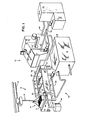
- Fig. 1 is a perspective view of a preferred embodiment apparatus for use in washing and drying formed battery plates.
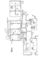
- Fig. 2 is a top plan view of the apparatus illustrated in Fig. 1.
- Although specific forms of the invention have been selected for illustration in the drawings, and the following description is drawn in specific terms for the purpose of describing these forms of the invention, this description is not intended to limit the scope of the invention which is defined in the appended claims.
- Figs. 1-2 illustrate a preferred embodiment apparatus designated generally 10 for use in connection with the manufacture of dry charge storage batteries. The apparatus 10 incorporates a washing section designated generally 12 and a drying section designated generally 13 which serially receive groups designated generally 14 of battery plates which have previously been manufactured and formed in accordance with conventional techniques. To enable movement of the battery plates between the forming apparatus (not shown), the
washing section 12, thedrying section 13, and subsequent handling equipment (not shown), a hoist mechanism designated generally 15 is provided which is capable of traversing arail 16 extending over and between the various portions of the dry charge apparatus 10. Thehoist mechanism 15 is provided with abasket 17 suspended from the hoist and capable of containing thegroups 14. - The
washing section 12 includes atank 18, apurifier 19, andfluid lines tank 18 and purifier 19.Thetank 18 is separated into at least two, and in the preferred embodiment shown, three cavities designated generally 22, 23, and 24 bypartitions adjacent cavities partition 26 extend upwardly to a height below the upper edge oftank 18. This optimizes uniformity in fluid flow between thecavities - The
cavity 22 is provided with adrain 29 in the bottom of thetank 18 connected by adrain line 30 to pump 32 to assist in the removal and handling of fluid drawn from thecavity 22.Discharge line 34 from thepump 32 pumps the used acidic waste water from thecavity 22 to aholding tank 36. This water has a high concentration of acid, and may be used for "cutting" new acid. Cutting is where sulfuric acid is diluted with water for use in other battery processes. - Water is added to the
slow flow cavity 22 of thetank 18 from thecooling tower 38 throughdischarge line 40. Flow of water into thetank cavity 22 is controlled by valve or metering device shown schematically at 42 inline 40. - The
fluid lines cavity 23 of thetank 18 and purifier 19. Thecavity 23 has adrain 44 in the bottom of thetank 18 in fluid flow communication with thedrain line 46 connected to the input of thepump 48 which discharges into theline 20 and thence into thepurifier 19. Thefluid line 21 discharges purified water from thepurifier 19 intocavity 24 of thetank 18. The fluid in thecavity 24 flows over thepartition 26 into thecavity 23. - The
drying section 13 generally includes adryer 45, acooling tower 38, andfluid lines - The present invention is directed to a system wherein formed battery plates are serially washed in water at various flow rates. In this preferred embodiment, the
tank 18 includes threecavities ano 24 which are used inwashing groups 14 of formed battery plates. The plates are first introduced into thecavity 22. Hot water at a slow flow rate from the cooling tower circulates gently from the top of the tank across the immersed plates and out the bottom through thedrain 29. The flow is adjusted so that the acid concentration of the fluid developed in thecavity 22 is preferably approximately in the range of 1 to 52 by weight. The acid concentration in the formed plates when they enter thecavity 22 is approximately 10% by weight. The acid concentration in the plates after the slow flow wash should be most preferably about in the range of 0.4 to 0.8%. The pH difference in concentrations before slow flow and after slow flow is about 1.3 or twenty times less acid in the plates; that is, 93 to 96% or most of the acid should have been removed from the plates. Thus the acid concentration of the water removed through thelines 34 and stored intank 36 is quite high compared to the prior art method of removing acid from the plates with a wash water at a high flow rate. The prior art method produced a large volume of acidic water which was very dilute compared to the slow flow rate method. The prior art methods produced a 0.1% acid (pH 1.70) on the average in all the water from the days activities. In the method in accordance with the present invention, it is desired to have the acid concentration of the waste water from the slow flow tank be in the range of 1% to 4% or pH of about .7 to .1. It will be understood that differences in concentrations will be a function of the rate at whichgroups 14 of the battery plates are immersed in thecavity 22 and the flow rate. - In drying the washed battery plates, fluid collected in the
dryer 45 is returned to thecooling tower 38 via thefluid line 50 and cooled. Thecooling tower 38 preferably incorporates a water softener to prevent scale build up, but does not drain waste fluid to the environment. Rather, such fluid is used in connection with subsequent drying, and in supplying make-up water at a slow flow rate to thetank 18cavity 22 through theline 40. - The fluid delivered to the
cavity 24 via thefluid line 21 should generally be maintained at a pH of 4 to 7. The primary means for regulating acid concentration within thecavities purifier 19 is preferably an ion exchange resin bed. The resin may have an ammonium group chemically bound onto it. Such a resin is for example, DUOLITE A-368 as manufactured by Duolite International, Inc., Diamond Shamrock, Corporation, 1100 Superior Avenue, Cleveland, Ohio. This is a macroporous weak-base anion exchange resin having, according to its technical literature, an exceptionally high operating capacity and efficiency for removal of mineral acids. Its relatively high basicity allows the absorption of weak acids having pK values below about 5. - The properties of DUOLITE A-316 according to their technical sheet are as follows:

- In accordance with the present invention, the used fast flow water from the
tank 18,cavity 23 exits through thedrain 44 and is pumped into thepurifier 19 wherein the acidic water forms a salt with the ion exchange resin. The salt is bonded to the resin and can not leave the purifier. What results is water which is virtually free of all acid, which is pumped back through theline 21 into the top of thetank 18 intocavity 24 for fast washing of the plates. - The reason for two cavities, 23 and 24 in the preferred fast wash section of the
tank 18 is to provide time to match the production of the dry charge machine. In operation,groups 14 of battery plates which have been appropriately formed are carried to thetank 18 by means of the hoistmechanism 15. Thesegroups 14 of battery plates are serially introduced into thecavities tank 18, for successive washing procedures. Upon withdrawal from thecavity 24, thegroups 14 of battery plates will have been thoroughly washed, and will be ready for subsequent introduction into thedryer 45; once again by means of the hoistmechanism 15. Upon drying, thegroups 14 of battery plates will be removed from thedryer 45 for subsequent handling; once again using the hoistmechanism 15. - Unlike previous systems used in connection with the production of dry charge battery plates, major portions of the foregoing apparatus are essentially "closed- looped". The only interfacing necessary with the apparatus 10 is a water inlet to the
cooling tower 38, for supplying water to the system. Also, purifying materials must be introduced into thepurifier 19 and waste materials must be drained from thepurifier 19. - In connection with this procedure, the largest acidic effluent to be accommodated is the discharge of the acid solution from the
drain 29 of thecavity 22. However, since such a solution is capable of use in connection with other portions of the battery manufacturing process, such wash water is conveniently delivered from the holdingtank 36 to a cutting tank (not shown) for subsequent processing either for use as electrolyte in connection with plate forming, or for use in producing the pastes which are applied to the battery plates. Accordingly, by appropriately adjusting the concentration of the effluent discharged from thedrain 29, as previously indicated, the bulk of the residual fluid produced by the system of the present invention is rendered reusable, rather than requiring its treatment and disposal by conventional prior art means. The criteria in accordance with the present invention is to keep the acid concentration high and the volume low so that most and preferably all of it can be used in other manufacturing processes. - While final washing of the battery plates at high flow rate produces acidic effluent, the acid is removed by means of the
purifier 19. Thepurifier 19 assists in managing waste by-products because the sludge delivered from the purifier will be significantly reduced from the waste by-products ordinarily delivered from previously available neutralization systems. While there is a large volume of water, it is at very low acid concentration. - For example, the following parameters should be considered in connection with the illustrative example previously provided in relation to an exemplary operation of a "Tiegel 200" dry charge apparatus. First, since the initial wash water need no longer completely remove all acid contained in the processed battery plates, the overall flow rate of the wash water may be reduced from 12.5 gallons per minute to 15 gallons per hour. Accordingly, rather than producing 12,000 gallons of wast. water per day, the present apparatus will produce 240 gallons of acid having a concentration in the range of about 1 to 4%, which is suitable in both quantity and concentration for use in connection with other portions of the battery manufacturing process.
- Most, that is approximately 93 to 96%, of the acid on the battery plates will be removed by this initial washing. This will leave approximately 4 to 7% of the acid for neutralization treatment in the
purifier 19. However, as a result of the materially reduced quantities of acid which remain to be removed by exchange techniques, the present invention only necessitates the disposal of approximately 16 to 28 lbs. of solid waste material per day, as opposed to the production of approximately 200 lbs. of solid waste material per day of prior art methods; resulting in the production of less than 1 to 3 tons of waste material per average work year. Because of the limited amounts of ion exchange resin needed within such a system, it is generally necessary to regenerate the purifier once each day. - Thus, the foregoing apparatus serves well to satisfy each of the objectives previously set forth, by managing the waste products resulting in material reductions in waste by-products and handling costs. As further evidence of the benefits which such a system is capable of providing, the following table shows several exemplary operations of the system. The first column indicates the number of plates which may be handled in connection with each illustrative example, per hour. The second column indicates the number of pounds of neutralizing material which must be supplied to the purifier, per day, assuming a 16 hour operating day. The third column indicates the number of gallons of acid which may be drained from the tank, per hour. Lastly, the fourth column indicates the number of gallons of waste material which will be produced by the purifier, per day, again assuming a 16 hour operating day.

- The system will produce useful quantities of acid for use in connection with other phases of the battery manufacturing process, and will produce only minimal quantities of waste by-products which must be separately disposed of. Further, the amount of water which must be supplied to the system, via the
inlet 66 is also kept to a minimum, thus enhancing the cost effectiveness of the system. - It will be understood that various changes in the details, materials and arrangement of parts which have been herein described and illustrated in order to explain the nature of this invention may be made by those skilled in the art within the principle and scope of the invention as expressed in the following claims.
Claims (17)
Priority Applications (1)
| Application Number | Priority Date | Filing Date | Title |
|---|---|---|---|
| AT85302047T ATE48724T1 (en) | 1984-03-29 | 1985-03-25 | METHOD OF TREATMENT OF WASTE PRODUCTS AND APPARATUS FOR REMOVING ACID FROM DRY CHARGED BATTERY PLATES. |
Applications Claiming Priority (2)
| Application Number | Priority Date | Filing Date | Title |
|---|---|---|---|
| US06/594,792 US4572746A (en) | 1984-03-29 | 1984-03-29 | Acid removal from dry charge battery plates |
| US594792 | 1984-03-29 |
Publications (3)
| Publication Number | Publication Date |
|---|---|
| EP0156642A2 true EP0156642A2 (en) | 1985-10-02 |
| EP0156642A3 EP0156642A3 (en) | 1987-02-04 |
| EP0156642B1 EP0156642B1 (en) | 1989-12-13 |
Family
ID=24380425
Family Applications (1)
| Application Number | Title | Priority Date | Filing Date |
|---|---|---|---|
| EP85302047A Expired EP0156642B1 (en) | 1984-03-29 | 1985-03-25 | Waste product management process and apparatus for use in removing acid from dry charge battery plates |
Country Status (4)
| Country | Link |
|---|---|
| US (1) | US4572746A (en) |
| EP (1) | EP0156642B1 (en) |
| AT (1) | ATE48724T1 (en) |
| DE (1) | DE3574800D1 (en) |
Cited By (1)
| Publication number | Priority date | Publication date | Assignee | Title |
|---|---|---|---|---|
| US5250711A (en) * | 1987-07-16 | 1993-10-05 | The Upjohn Company | Amine salts of alkane-1,n-dicarboxylic acid mono-(2-sulfato-ethyl) amides |
Families Citing this family (8)
| Publication number | Priority date | Publication date | Assignee | Title |
|---|---|---|---|---|
| US4654089A (en) * | 1985-05-31 | 1987-03-31 | Singelyn Daniel D | Counterflow spray rinse process |
| DE3934938A1 (en) * | 1989-10-17 | 1991-04-18 | Hagen Batterie Ag | METHOD OF PREVENTING LEAD DUST TRAILING IN THE MANUFACTURE AND ASSEMBLY OF LEAD / SOFT BATTERY ELECTRODE PLATES |
| US5034065A (en) * | 1990-01-16 | 1991-07-23 | Tiegel Manufacturing Company | Method for washing storage batteries |
| US5095926A (en) * | 1990-01-16 | 1992-03-17 | Wegner Paul C | Apparatus for washing storage batteries |
| US5265630A (en) * | 1991-08-09 | 1993-11-30 | Robert Hartmann | Environmentally-friendly battery cleaning system |
| US5186758A (en) * | 1991-08-09 | 1993-02-16 | Robert Hartman | Environmentally-friendly battery cleaning method |
| US5590671A (en) * | 1995-09-25 | 1997-01-07 | East Penn Manufacturing Co., Inc. | Mobile battery cleaning system |
| JP7159877B2 (en) * | 2019-01-08 | 2022-10-25 | トヨタ自動車株式会社 | battery cooling system |
Family Cites Families (9)
| Publication number | Priority date | Publication date | Assignee | Title |
|---|---|---|---|---|
| US2911457A (en) * | 1955-03-29 | 1959-11-03 | Globe Union Inc | Method and apparatus for making dry charged batteries |
| US3761381A (en) * | 1966-10-18 | 1973-09-25 | A Yagishita | Plating waste recovery unit |
| GB1220495A (en) * | 1968-04-05 | 1971-01-27 | Tiegel Mfg Company | A method and apparatus for drying charged battery plates |
| IT1017643B (en) * | 1973-11-15 | 1977-08-10 | Ebara Udylite Kk | METHOD AND APPARATUS FOR TREATMENT AND SOLUTIONS FOR SURFACE TREATMENT OF METALS AND WASHING LIQUIDS |
| US4024055A (en) * | 1974-08-01 | 1977-05-17 | Globe-Union Inc. | Method of reducing lead and acid waste contamination in battery plant operation |
| DE2621996A1 (en) * | 1976-05-18 | 1977-12-01 | Varta Batterie | METHOD OF MANUFACTURING A LEAD ACCUMULATOR |
| US4396435A (en) * | 1980-06-24 | 1983-08-02 | General Electric Company | Fluid handling system |
| DE3173910D1 (en) * | 1981-11-20 | 1986-04-03 | Sanshin Seisakusho Kk | Method and apparatus for recycling washing liquid and heat contained in washings discharged from metal surfacing process |
| US4451298A (en) * | 1981-12-08 | 1984-05-29 | Kabushiki Kaisha Sanshin Seisakusho | Method and system for recycling washing liquids and the heat contained therein |
-
1984
- 1984-03-29 US US06/594,792 patent/US4572746A/en not_active Expired - Lifetime
-
1985
- 1985-03-25 AT AT85302047T patent/ATE48724T1/en not_active IP Right Cessation
- 1985-03-25 EP EP85302047A patent/EP0156642B1/en not_active Expired
- 1985-03-25 DE DE8585302047T patent/DE3574800D1/en not_active Expired - Lifetime
Cited By (1)
| Publication number | Priority date | Publication date | Assignee | Title |
|---|---|---|---|---|
| US5250711A (en) * | 1987-07-16 | 1993-10-05 | The Upjohn Company | Amine salts of alkane-1,n-dicarboxylic acid mono-(2-sulfato-ethyl) amides |
Also Published As
| Publication number | Publication date |
|---|---|
| EP0156642B1 (en) | 1989-12-13 |
| EP0156642A3 (en) | 1987-02-04 |
| US4572746A (en) | 1986-02-25 |
| ATE48724T1 (en) | 1989-12-15 |
| DE3574800D1 (en) | 1990-01-18 |
Similar Documents
| Publication | Publication Date | Title |
|---|---|---|
| US3959133A (en) | Alum recovery and waste disposal in water treatment | |
| EP0156642B1 (en) | Waste product management process and apparatus for use in removing acid from dry charge battery plates | |
| CN112725942A (en) | Viscose sodium sulfate waste liquid regeneration and recycling process | |
| CN106430787B (en) | A kind of APT production wastewater recycling method | |
| RU2095448C1 (en) | Method and apparatus for recovering gold from low-grade ores | |
| US3862032A (en) | Ion exchange waste water treatment process | |
| US4231960A (en) | Process for the purification of urea solutions containing biuret and the like | |
| RU96123204A (en) | METHOD FOR REMOVING NICKEL FROM WASTE SOLUTIONS OF ELECTRICAL PRODUCTION | |
| EP0068413B1 (en) | Method of using higher concentration sulfuric acid for stripping and precipitation of adsorbed magnesium | |
| CA1099491A (en) | Process for removing chlorine ions from the wet flue- gas processing system | |
| CN216377740U (en) | High ammonia-nitrogen wastewater treatment and resource utilization system | |
| JPH10192718A (en) | Resin regeneration equipment for condensate desalination equipment | |
| JPS5528738A (en) | Regenerating method of mixed ion exchange resin | |
| US4002455A (en) | Process for treating and recovering waste water from the fertilizer manufacture | |
| US2397650A (en) | Manufacture of glue | |
| JPS5591979A (en) | Recovering and circulating apparatus for alkaline etching waste solution | |
| JPS5827985A (en) | Controlling method for dip coating type phosphating | |
| CN218795028U (en) | Optimization device for wet sodium-based desulfurization process | |
| SU1627245A1 (en) | Method for rejuvenation of cation and anion exchangers in water demineralizing and softening plants | |
| JPH09122502A (en) | Method for filling ion-exchange resin in desalting tower and desalting apparatus | |
| CA1115484A (en) | Pretreatment method for the recovery of uranium from wet-process phosphoric acid | |
| SU856543A1 (en) | Method of regeneration of strong-acidic cationic exchanger | |
| GB1563480A (en) | Method for decontaminating the aqueous effluents | |
| US3098711A (en) | Recovery of hafnium hydroxide | |
| KR102064063B1 (en) | Material collecting apparatus using wastewater and method therefor |
Legal Events
| Date | Code | Title | Description |
|---|---|---|---|
| PUAI | Public reference made under article 153(3) epc to a published international application that has entered the european phase |
Free format text: ORIGINAL CODE: 0009012 |
|
| AK | Designated contracting states |
Designated state(s): AT BE CH DE FR GB IT LI LU NL SE |
|
| PUAL | Search report despatched |
Free format text: ORIGINAL CODE: 0009013 |
|
| AK | Designated contracting states |
Kind code of ref document: A3 Designated state(s): AT BE CH DE FR GB IT LI LU NL SE |
|
| 17P | Request for examination filed |
Effective date: 19870401 |
|
| 17Q | First examination report despatched |
Effective date: 19880210 |
|
| GRAA | (expected) grant |
Free format text: ORIGINAL CODE: 0009210 |
|
| AK | Designated contracting states |
Kind code of ref document: B1 Designated state(s): AT BE CH DE FR GB IT LI LU NL SE |
|
| PG25 | Lapsed in a contracting state [announced via postgrant information from national office to epo] |
Ref country code: SE Effective date: 19891213 Ref country code: NL Effective date: 19891213 Ref country code: LI Effective date: 19891213 Ref country code: IT Free format text: LAPSE BECAUSE OF FAILURE TO SUBMIT A TRANSLATION OF THE DESCRIPTION OR TO PAY THE FEE WITHIN THE PRESCRIBED TIME-LIMIT;WARNING: LAPSES OF ITALIAN PATENTS WITH EFFECTIVE DATE BEFORE 2007 MAY HAVE OCCURRED AT ANY TIME BEFORE 2007. THE CORRECT EFFECTIVE DATE MAY BE DIFFERENT FROM THE ONE RECORDED. Effective date: 19891213 Ref country code: FR Free format text: THE PATENT HAS BEEN ANNULLED BY A DECISION OF A NATIONAL AUTHORITY Effective date: 19891213 Ref country code: CH Effective date: 19891213 Ref country code: BE Effective date: 19891213 Ref country code: AT Effective date: 19891213 |
|
| REF | Corresponds to: |
Ref document number: 48724 Country of ref document: AT Date of ref document: 19891215 Kind code of ref document: T |
|
| REF | Corresponds to: |
Ref document number: 3574800 Country of ref document: DE Date of ref document: 19900118 |
|
| REG | Reference to a national code |
Ref country code: CH Ref legal event code: PL |
|
| PG25 | Lapsed in a contracting state [announced via postgrant information from national office to epo] |
Ref country code: LU Free format text: LAPSE BECAUSE OF NON-PAYMENT OF DUE FEES Effective date: 19900331 |
|
| EN | Fr: translation not filed | ||
| NLV1 | Nl: lapsed or annulled due to failure to fulfill the requirements of art. 29p and 29m of the patents act | ||
| PLBE | No opposition filed within time limit |
Free format text: ORIGINAL CODE: 0009261 |
|
| STAA | Information on the status of an ep patent application or granted ep patent |
Free format text: STATUS: NO OPPOSITION FILED WITHIN TIME LIMIT |
|
| 26N | No opposition filed | ||
| REG | Reference to a national code |
Ref country code: GB Ref legal event code: IF02 |
|
| PGFP | Annual fee paid to national office [announced via postgrant information from national office to epo] |
Ref country code: GB Payment date: 20040324 Year of fee payment: 20 |
|
| PGFP | Annual fee paid to national office [announced via postgrant information from national office to epo] |
Ref country code: DE Payment date: 20040401 Year of fee payment: 20 |
|
| PG25 | Lapsed in a contracting state [announced via postgrant information from national office to epo] |
Ref country code: GB Free format text: LAPSE BECAUSE OF EXPIRATION OF PROTECTION Effective date: 20050324 |
|
| REG | Reference to a national code |
Ref country code: GB Ref legal event code: PE20 |