EP0156457A1 - Component insertion apparatus - Google Patents
Component insertion apparatus Download PDFInfo
- Publication number
- EP0156457A1 EP0156457A1 EP85300532A EP85300532A EP0156457A1 EP 0156457 A1 EP0156457 A1 EP 0156457A1 EP 85300532 A EP85300532 A EP 85300532A EP 85300532 A EP85300532 A EP 85300532A EP 0156457 A1 EP0156457 A1 EP 0156457A1
- Authority
- EP
- European Patent Office
- Prior art keywords
- cam
- strip
- severing
- camshaft
- workpiece
- Prior art date
- Legal status (The legal status is an assumption and is not a legal conclusion. Google has not performed a legal analysis and makes no representation as to the accuracy of the status listed.)
- Granted
Links
Images


Classifications
-
- H—ELECTRICITY
- H01—ELECTRIC ELEMENTS
- H01R—ELECTRICALLY-CONDUCTIVE CONNECTIONS; STRUCTURAL ASSOCIATIONS OF A PLURALITY OF MUTUALLY-INSULATED ELECTRICAL CONNECTING ELEMENTS; COUPLING DEVICES; CURRENT COLLECTORS
- H01R43/00—Apparatus or processes specially adapted for manufacturing, assembling, maintaining, or repairing of line connectors or current collectors or for joining electric conductors
- H01R43/20—Apparatus or processes specially adapted for manufacturing, assembling, maintaining, or repairing of line connectors or current collectors or for joining electric conductors for assembling or disassembling contact members with insulating base, case or sleeve
- H01R43/205—Apparatus or processes specially adapted for manufacturing, assembling, maintaining, or repairing of line connectors or current collectors or for joining electric conductors for assembling or disassembling contact members with insulating base, case or sleeve with a panel or printed circuit board
-
- H—ELECTRICITY
- H05—ELECTRIC TECHNIQUES NOT OTHERWISE PROVIDED FOR
- H05K—PRINTED CIRCUITS; CASINGS OR CONSTRUCTIONAL DETAILS OF ELECTRIC APPARATUS; MANUFACTURE OF ASSEMBLAGES OF ELECTRICAL COMPONENTS
- H05K13/00—Apparatus or processes specially adapted for manufacturing or adjusting assemblages of electric components
- H05K13/04—Mounting of components, e.g. of leadless components
- H05K13/0417—Feeding with belts or tapes
-
- Y—GENERAL TAGGING OF NEW TECHNOLOGICAL DEVELOPMENTS; GENERAL TAGGING OF CROSS-SECTIONAL TECHNOLOGIES SPANNING OVER SEVERAL SECTIONS OF THE IPC; TECHNICAL SUBJECTS COVERED BY FORMER USPC CROSS-REFERENCE ART COLLECTIONS [XRACs] AND DIGESTS
- Y10—TECHNICAL SUBJECTS COVERED BY FORMER USPC
- Y10T—TECHNICAL SUBJECTS COVERED BY FORMER US CLASSIFICATION
- Y10T29/00—Metal working
- Y10T29/51—Plural diverse manufacturing apparatus including means for metal shaping or assembling
- Y10T29/5136—Separate tool stations for selective or successive operation on work
- Y10T29/5137—Separate tool stations for selective or successive operation on work including assembling or disassembling station
- Y10T29/5142—Separate tool stations for selective or successive operation on work including assembling or disassembling station and means to sever work from supply
-
- Y—GENERAL TAGGING OF NEW TECHNOLOGICAL DEVELOPMENTS; GENERAL TAGGING OF CROSS-SECTIONAL TECHNOLOGIES SPANNING OVER SEVERAL SECTIONS OF THE IPC; TECHNICAL SUBJECTS COVERED BY FORMER USPC CROSS-REFERENCE ART COLLECTIONS [XRACs] AND DIGESTS
- Y10—TECHNICAL SUBJECTS COVERED BY FORMER USPC
- Y10T—TECHNICAL SUBJECTS COVERED BY FORMER US CLASSIFICATION
- Y10T29/00—Metal working
- Y10T29/51—Plural diverse manufacturing apparatus including means for metal shaping or assembling
- Y10T29/5147—Plural diverse manufacturing apparatus including means for metal shaping or assembling including composite tool
- Y10T29/5148—Plural diverse manufacturing apparatus including means for metal shaping or assembling including composite tool including severing means
- Y10T29/5149—Plural diverse manufacturing apparatus including means for metal shaping or assembling including composite tool including severing means to sever electric terminal from supply strip
Definitions
- This invention relates to apparatus for severing components from a strip thereof and inserting each severed component into a workpiece, the components being, for example, electrical terminals and the workpiece being, for example, a circuit board.
- Such apparatus is disclosed in US-A-3,276,653, the apparatus comprising a component insertion tool, means for feeding the strip of components incrementally towards a strip severing station with one of the components leading, means for severing the leading component from the strip at the severing station, a drive motor, a camshaft operatively connected thereto, camming means on the camshaft connected to the insertion tool, to the strip feeding means and the strip severing means, to cause them to be driven by the motor so that the leading component is fed to the severing station and is there severed from the strip, and is then inserted into the workpiece by the insertion tool.
- the invention proceeds from the realization that the moving parts of such a machine can, by suitable selection and arrangement thereof, be reduced in mass, to such an extent that the speed of the machine is substantially doubled in relation to that of the known machine.
- the camshaft has thereon a disc cam having formed in a face thereof at least one first endless cam track for a cam follower connected to the insertion tool and on its opposite face at least one second endless cam track for a cam follower connected to the severing means, the strip feeding means being driven by a further cam on the camshaft, which cam is spaced from the disc cam in the feed direction of the strip of components, and has thereon an endless third cam track for a cam follower connected to the strip feeding means, the strip severing means and the insertion tool being arranged substantially in the same plane.
- the cam tracks can be so designed and the motor, which is preferably connected to the camshaft through step down transmission means, so controlled that the motion of the driven parts is both smooth and rapid.
- the optimum shape for the disc cam tracks to balance out the torque demands on the motor can be achieved by computer analysis of the dynamics of the mechanism. The need for only two cams reduces the mass of the parts to be driven by the motor, as well as the relative arrangement of the insertion tool, the severing means, the further cam and the component feed means, so that the connections between these parts can be as short and simple as possible.
- the insertion tool may be in the form of a pair of jaws for gripping such a component as an electrical post and the severing means may comprise two blades, both of which are movable, without unduly increasing the inertia of the parts driven by the motor.
- the workpiece which may be moved relative to the insertion tool by means of an X-Y table, may be supported by a tool therebeneath during each insertion stroke of the insertion tool, this lower tool being driven also by a stepping motor in synchronization with the rotation of the main camshaft.
- the apparatus may be provided with monitoring means arranged to activate a control system to stop the apparatus in the event of a malfunction.
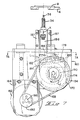
- the apparatus As shown in Figure 1, the apparatus, which is generally referenced 2, has its upper part 3 mounted above an X-Y table 4, which is in turn mounted upon a workbench 6. The lower part of the apparatus, which is not shown in Figure 1, is mounted in the workbench 6 below the X-Y table 4.
- a circuit board 8 is positioned on the X-Y table above an opening therein.
- a storage reel 10 upon which is wound a strip 12 of electrical post terminals is mounted on a bracket 14 secured to the worktable 6.
- the strip 12 is led through a guide channel 13 into the upper part of the apparatus from the rear (as seen in Figure 1).
- Also mounted on the worktable 6 are electronic control units 16 and 18, respectively, for the insertion apparatus, and for the X-Y table.
- the unit 16 has a cathode ray tube display 15 and a control panel 17. Since the X-Y table and its control unit are conventional, they will not be further described in this specification.
- the strips 12 of electrical posts comprises a carrier strip 20 which connects together, intermediate their ends, electrical posts 22.
- the strip having been fed by a feed pawl 21 as described below, by one increment in the direction of the arrow A in Figure 2, during the previous cycle, the leading post 22a is positioned at a strip severing station 24 as shown in Figure 2.
- a pair of insertion jaws 30 and 31 are in a closed position so as to grip the upper part of the leading post 22a.
- the leading post 22a is positioned in alignment with a hole 32 in the circuit board 8 in which the post 22a is to be inserted.
- the punch 26 and the die 28 are now moved apart from one another, and the jaws 30 and 31 with the post 72a gripped between them descend in the direction of the arrow B so that the post 22a is inserted into the hole 32. Whilst the jaws 30 and 31 are descending, the support tool 34 rises in the direction of the arrow C so as to abut the lower face of the circuit board 8 to support it as the post 22a is inserted into the hole 32, the lower part of the post 22a being received in the hole 36 in the tool 34.
- the upper part of the apparatus can be used independently of the lower part, for example, with a passive board support or with workpiece indexing means other than an X-Y table.
- the apparatus comprises a frame generally referenced 40 to the upper part of which is secured a stepping motor 42 by means of fasteners 43, as best seen in Figures 6 and 8.
- An electric fan 44 is secured to a crossplate 46 of the frame 40 to cool the motor so that maximum power may be drawn therefrom.
- a sprocket wheel 48 fixed to the shaft 50 of the motor 42 is connected to a drive sprocket wheel 52 fixed to a main camshaft 54 of the apparatus, hy means of a toothed belt 56 which may be made of a synthetic rubber material so that its mass is minimal.
- the sprocket wheel 52 has openings 58 which are provided in order to reduce its mass.
- Below the motor 42 is secured a revolution counter 59 for the motor 42.
- the main camshaft 54 is mounted in bearings 60 and 62 in the frame 40.
- a first absolute encoder 66 also mounted in the frame 40 is connected to the shaft 54 by means of a belt 68 and sprocket 69, to continuously monitor the angular position of the shaft 54.
- Fixed to the shaft 54 are a disc cam 70 through which the jaws 30 and 31 are opened and closed and driven through their vertical motions, and a barrel cam 72 through which the means, described below, for feeding the strip 12 is driven.
- the punch 26 and die 28 are also driven through the disc cam 70.
- the cam 70 has formed in its front face, as best seen in Figure 10, a first outer cam track 74 and a second inner cam track 76.
- the jaw 31 is formed integrally with the carrier 80 and the jaw 30 is pivoted thereto at 82.
- the jaws have post-gripping surfaces 84 near their free ends. That end 85 of the jaw 30, which is remote from its gripping surface 84, is provided with a pair of springs 102 which engage in, and are contained in, bores 88 in the jaw carrier 80 which is slidably mounted in a front plate 90 of the frame 40.
- a cam follower 92, which rides in the cam track 76, is connected to a rocker arm 94 which is pivoted to the plate 90 at 96, intermediate the ends of the arm 94.
- the arm 94 At its end remote from the cam follower 92, the arm 94 has a jaw actuating projection 98 extending normally thereof and having at its free end a roller 100 engaging the part 85 of the jaw 30.
- the jaw 30 is urged towards its closed position as shown in Figure 10 by the springs 102.
- the jaw carrier 80 As the cam 70 rotates in the direction of the arrow F in Figure 10, the jaw carrier 80 is raised and lowered as indicated by the arrow G in Figure 10 to move the jaws 30 and 31 between the vertical positions described with reference to Figures 2 to 5.
- the arm 94 is rocked between the position shown in Figure 10, in which the jaws 30 and 31 are closed, to a position in which the roller 100 compresses the springs 102 into the bores 88 against the action of the springs 102 so that the jaws 30 and 31 are opened when, as illustrated in Figure 5, they are in their fully-raised position so that the strip 12 of posts can be advanced by a step.
- the cam 70 is formed on its rear side with respective inner and outer cam tracks 104 and 106.
- An air blast pipe 123 ( Figure 6) is provided for the removal of a post which remains stuck to the jaw 30 or 31 after these jaws have been withdrawn from the circuit board, the air being supplied under the control of the control unit when the jaws are open.
- the barrel cam 72 which is spaced rearwardly of the cam 70, has a cam track 130 in which rides a cam follower 13? fixed to a lever 134 which is pivoted intermediate its ends in a clevis 136 secured to the rear plate 138 of the frame 40 on a pivot pin 140 provided with an eccentric mounting 142 which can be rotated to adjust the throw of the link 134.
- the end of the lever 134 remote from the cam follower 132 is pivoted at 144 to a link 146, which is in turn pivoted to a feed slide 148 which carries the feed pawl 21 and which is slidable in a channel 150 in a feed block 152.
- the strip 1? extends through a strip guide channel 151 in the block 152.
- This part of the apparatus comprises a frame 160 to which is mounted a further stepping motor 162 on a plate 164 secured to the plate 160.
- the shaft 166 of the motor 122 is connected by means of a toothed belt 168 of a synthetic rubber material to a further disc cam 170 which is mounted on a camshaft 172 rotatably mounted in the frame 160, the cam 170 having a cam track 174 in which rides a cam follower 176 pivotally connected to a link 178 intermediate the ends thereof.
- end of the link 178 is pivoted to the frame 160 at 180, the opposite end of the link 178 being pivoted to one end of a further link 182 at 184.
- the other end of the link 182 is pivoted to a slide 186 at 188, which slide carries the supporting tool 134 and is slidable between gibs 187.
- the cam 170 is rotated by the motor 162 in the direction of the arrow J in Figure 7, the tool 34 is moved by the slide 186 between its retracted position and its board supporting position in the manner described with reference to Figures 2 to 5.
- the shaft 172 is connected to an absolute encoder 190, which continuously measures the angular position of the shaft 172.
- the belt 168 is engaged about a sprocket wheel 192 on the motor shaft 166 and a sprocket wheel 194 on the camshaft 172.
- the motion of the slide 186 is indicated by the arrows K in Figure 7, the motion of the pivot point 184 being indicated by the arrow L in Figure 7.
- Figure 11 is a timing diagram which indicates how the tooling described above is synchronized by means of the cam tracks, this tooling as a lot being synchronized electronically.
- the angular positions of the camshafts 54 and 172 are plotted against the movement of the tooling as represented by schematic developed views of the cam tracks 74, 76, 130, 104 and 106, and 174.
- the insertion tool (cam track 74) starts to descend so as to insert the post 22a into the hole 32, the insertion of the post beginning at broken line M and full insertion being indicated by broken line N.
- the roller 100 (cam track 76) begins to open the jaw 30, which is fully opened, for a dwell period, shortly after the insertion tool reaches its fully raised position. Whilst the jaw 30 is still in its open position, the feed pawl 21 (cam track 130) advances the strip 12 so that the leading post is positioned at the severing station 24, after which the jaw 30 is closed so that the Jaws 30 and 31 grip the post, the jaw 30 having dwelt in its open position during the greater part of the feed stroke of the pawl 21 which dwells in its fully advanced position during the strip severing operation.
- the die 28 (cam track 104) is advanced against the carrier strip 20 and dwells in such position whilst the punch 26 (cam track 106) severs the carrier strip as indicated by the broken lines P and Q, after which the insertion tool descends again.
- the board supporting tool 34 (cam track 174) is moved to its advanced, supporting, position prior to the insertion of the post into the hole 32 and is then retracted to allow the X-Y table to be indexed, following a dwell period during the insertion operation.
- FIG 12 is a block schematic diagram of the control unit 16 for the apparatus 2. Certain parts of the unit are duplicated to allow for the case where the apparatus is provided with dual insertion tooling for operation with the same X-Y table. The reference numerals of the duplicated parts are indicated by a prime symbol.
- items not previously referred to are referenced as follows: a central microprocessor is referenced MP, miscellaneous sensors are referenced MS, indexers in the form of indexing pulse transmitters for the stepping motors as 1, drivers for the motors as D, head code means as HC, and a synchronizing control device for the X-Y table as CNC.
- the miscellaneous sensors MS which are for the pre-inspection of the strip 12, are arranged in the feed track for the detection of a splice or overlap in the strip 12, a post that protrudes from the plane of the strip 12, and the exhaustion of the supply of the strip 12, and for other desired inspection purposes.
- the encoders 66 and 190 which continuously measure the angular positions of the shafts 54 and 172, respectively, of the motors 42 and 162 may be absolute optical encoders or electromagnetic resolvers.
- the head code means is an electrical connector which has been jumpered to select a desired program for the operation of the apparatus from the memory of the microprocessor and the appropriate angular positions of the shaft 54 for the program. There is no head code means for the motor 162, because the program for the shaft 54 dominates.
- the head code means may also indicate to the microprocessor as to whether the encoders are properly connected to the control circuit.
- the computer numeric control CNC for the X-Y table is connected by a "hand shaking" line to the microprocessor MP for the synchronization of the operation of the apparatus 2 and that of the X-Y table.
- the pulse transmitter I supplies the stepping motors 42 and 162 with actuating pulses via the respective impedance matching drivers D.
- the stepping motors 42 and 162 turn their shafts through angles predetermined by the number of pulses fed thereto and the transmitter I is programmed to produce the correct number of pulses for each cycle of operation of the apparatus 2.
- a pulse divider PD may be interposed between the I and one of the motors if the number of pulses required by that motor is different from that required by the other.
- the cathode ray display 15 indicates data relevant to the operation of the apparatus, under the control of the microprocessor.
- the microprocessor receives data from the miscellaneous sensors, the head code, the encoders 66 and 190, the computer numeric control for the X-Y table, and the control panel 17.
- a pushbutton On the control panel 17 are a number of, e.g., five, pushbuttons, the function of which will depend on the information displayed on the display 15. For example, according to the information displayed, a pushbutton may become a start button, or a "jog" button, or a stop button, or it may become a means of answering a question posed on the display.
- the microprocessor MP compares data from its own memory as determined by the head code means HC with that supplied by the encoders 66 and 190. If the shafts 54 and 172 are not in their home positions, as determined by the selected program, the microprocessor will not actuate the transmitter I so that the motors 42 and 162 do not start, and the actual angular positions of the shaft 54 and 172 are indicated on the cathode ray tube display 15. If this should occur, the display instructs the operator which button on the panel 17 to press in order to return the shafts 54 and 172 automatically to their home positions, so that the apparatus 2 is ready to be started.
- the motors 42 and 162 will also not be started if the microprocessor receives error data supplied by one of the miscellaneous sensors MS, the head code means HC, or the computer numeric control CNC for the X-Y table, and the fault is indicated on the cathode ray tube display 15 as well as instructions for clearing the fault.
- the microprocessor If the microprocessor receives error data whilst the apparatus 2 is In operation, it deactivates the transmitter I and thus the stepping motors, and the fault is indicated on the cathode ray tube display 15.
Landscapes
- Engineering & Computer Science (AREA)
- Manufacturing & Machinery (AREA)
- Microelectronics & Electronic Packaging (AREA)
- Perforating, Stamping-Out Or Severing By Means Other Than Cutting (AREA)
- Manufacturing Of Electrical Connectors (AREA)
- Supply And Installment Of Electrical Components (AREA)
- Making Paper Articles (AREA)
Abstract
Description
- This invention relates to apparatus for severing components from a strip thereof and inserting each severed component into a workpiece, the components being, for example, electrical terminals and the workpiece being, for example, a circuit board.
- Such apparatus is disclosed in US-A-3,276,653, the apparatus comprising a component insertion tool, means for feeding the strip of components incrementally towards a strip severing station with one of the components leading, means for severing the leading component from the strip at the severing station, a drive motor, a camshaft operatively connected thereto, camming means on the camshaft connected to the insertion tool, to the strip feeding means and the strip severing means, to cause them to be driven by the motor so that the leading component is fed to the severing station and is there severed from the strip, and is then inserted into the workpiece by the insertion tool.
- In this known apparatus, the motor is connected to the camshaft through a single revolution clutch, the camming means comprising a series of cams spaced axially of the camshaft, there being a separate cam for each piece of tooling to be driven, the cams, driving the tooling, each through a somewhat complex linkage.
- The invention proceeds from the realization that the moving parts of such a machine can, by suitable selection and arrangement thereof, be reduced in mass, to such an extent that the speed of the machine is substantially doubled in relation to that of the known machine.
- According to the invention, in apparatus as defined in the second paragraph of this specification, the camshaft has thereon a disc cam having formed in a face thereof at least one first endless cam track for a cam follower connected to the insertion tool and on its opposite face at least one second endless cam track for a cam follower connected to the severing means, the strip feeding means being driven by a further cam on the camshaft, which cam is spaced from the disc cam in the feed direction of the strip of components, and has thereon an endless third cam track for a cam follower connected to the strip feeding means, the strip severing means and the insertion tool being arranged substantially in the same plane.
- The cam tracks can be so designed and the motor, which is preferably connected to the camshaft through step down transmission means, so controlled that the motion of the driven parts is both smooth and rapid. The optimum shape for the disc cam tracks to balance out the torque demands on the motor can be achieved by computer analysis of the dynamics of the mechanism. The need for only two cams reduces the mass of the parts to be driven by the motor, as well as the relative arrangement of the insertion tool, the severing means, the further cam and the component feed means, so that the connections between these parts can be as short and simple as possible.
- The transmission means can consist of a toothed belt drive between a sprocket on the motor and a sprocket on the first camshaft. The sprockets may be formed with openings to reduce their weight and the belt can be of a synthetic rubber material.
- By virtue of the arrangement of the parts, the insertion tool may be in the form of a pair of jaws for gripping such a component as an electrical post and the severing means may comprise two blades, both of which are movable, without unduly increasing the inertia of the parts driven by the motor.
- The workpiece, which may be moved relative to the insertion tool by means of an X-Y table, may be supported by a tool therebeneath during each insertion stroke of the insertion tool, this lower tool being driven also by a stepping motor in synchronization with the rotation of the main camshaft.
- The apparatus may be provided with monitoring means arranged to activate a control system to stop the apparatus in the event of a malfunction.
- For a better understanding of the invention and so that yet further advantages thereof may be understood, an embodiment of the invention will now be described by way of example to the accompanying drawings, in which:
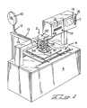
- FIGURE 1 is a perspective view of apparatus for separating components in the form of electrical post terminals from a carrier strip by which they are connected together and inserting the separated terminals one by one into a workpiece in the form of a circuit board, the apparatus being shown in a typical environment in association with an X-Y table mounted on a worktable and respective control units for the apparatus and for the X-Y table;
- FIGURES 2 to 5 are schematic perspective views illustrating successive stages in the operation of the basic tooling of the apparatus;
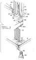
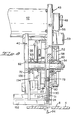
- FIGURE 6 is a diagrammatic frontal view of the upper part of the apparatus;
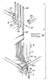
- FIGURE 7 is a diagrammatic frontal view of the lower part of the apparatus;
- FIGURE 7A is a view taken on the
lines 7A-7A in Figure 7; - FIGURE 8 is a side view of the upper part of the apparatus, shown partly in axial section through the camshaft thereof;
- FIGURE 9 is a-diagrammatic side view of the upper part of the apparatus taken from the opposite side to that from which Figure 8 was taken;
- FIGURE 9A is a view taken on the
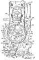
lines 9A-9A in Figure 9; - FIGURE 10 is a view taken on the lines 10-10 in Figure 8;
- FIGURE 10A is a view taken on the lines 10A-10A in Figure 9;
- FIGURE 11 is a timing diagram illustrating the sequential operation of the parts of the apparatus; and
- FIGURE 12 is a block schematic diagram of the control circuit of the apparatus.
- As shown in Figure 1, the apparatus, which is generally referenced 2, has its upper part 3 mounted above an X-Y table 4, which is in turn mounted upon a
workbench 6. The lower part of the apparatus, which is not shown in Figure 1, is mounted in theworkbench 6 below the X-Y table 4. Acircuit board 8 is positioned on the X-Y table above an opening therein. Astorage reel 10 upon which is wound astrip 12 of electrical post terminals is mounted on abracket 14 secured to theworktable 6. Thestrip 12 is led through aguide channel 13 into the upper part of the apparatus from the rear (as seen in Figure 1). Also mounted on theworktable 6 areelectronic control units unit 16 has a cathoderay tube display 15 and acontrol panel 17. Since the X-Y table and its control unit are conventional, they will not be further described in this specification. - A cycle of operation of the basic tooling of the apparatus will now be described in outline with reference to Figures 2 to 5. The
strips 12 of electrical posts comprises acarrier strip 20 which connects together, intermediate their ends,electrical posts 22. The strip having been fed by afeed pawl 21 as described below, by one increment in the direction of the arrow A in Figure 2, during the previous cycle, the leadingpost 22a is positioned at astrip severing station 24 as shown in Figure 2. At the stage of the operating cycle of the apparatus, which is shown in Figure 2, a pair ofinsertion jaws post 22a. The leadingpost 22a is positioned in alignment with ahole 32 in thecircuit board 8 in which thepost 22a is to be inserted. A supportingtool 34 beneath thecircuit board 8 is, at this stage in the cycle of operation, positioned below theboard 8, as shown in Figure 2, with a circular post-receiving opening 36 of thetool 34 in alignment with thehole 32. As shown in Figure 3, asevering punch 26 and a severingdie 28 are now moved towards one another, by means described below, to shear out theslug 38 of thecarrier strip 20 by which thepost 22a is connected to the nextadjacent post 22, the slug being driven, by air blast means (not shown), down achannel 40 formed in asupport 42 for thepunch 26. As shown in Figure 4, thepunch 26 and thedie 28 are now moved apart from one another, and thejaws post 22a is inserted into thehole 32. Whilst thejaws support tool 34 rises in the direction of the arrow C so as to abut the lower face of thecircuit board 8 to support it as thepost 22a is inserted into thehole 32, the lower part of thepost 22a being received in thehole 36 in thetool 34. As shown in Figure 5, when thepost 22a has been fully inserted into the hole in the circuit board, thetool 34 is retracted from theboard 8 in the direction of the arrow D and thejaws board 8 in the direction of the arrow E, sliding upwardly along the upper part of thepost 22a which is now firmly fixed in theboard 8. When thejaws strip 12 to be advanced by thepawl 21 in the direction of the arrow A so that thepost 22b next following thepost 22a is located at thestrip severing station 24. - The upper part of the apparatus can be used independently of the lower part, for example, with a passive board support or with workpiece indexing means other than an X-Y table.
- The apparatus will now be described in greater detail with reference to Figures 6 to 11.
- The apparatus comprises a frame generally referenced 40 to the upper part of which is secured a
stepping motor 42 by means offasteners 43, as best seen in Figures 6 and 8. Anelectric fan 44 is secured to acrossplate 46 of theframe 40 to cool the motor so that maximum power may be drawn therefrom. Asprocket wheel 48 fixed to theshaft 50 of themotor 42 is connected to adrive sprocket wheel 52 fixed to amain camshaft 54 of the apparatus, hy means of atoothed belt 56 which may be made of a synthetic rubber material so that its mass is minimal. Thesprocket wheel 52 hasopenings 58 which are provided in order to reduce its mass. Below themotor 42 is secured arevolution counter 59 for themotor 42. As best seen in Figure 8, themain camshaft 54 is mounted inbearings frame 40. A firstabsolute encoder 66 also mounted in theframe 40 is connected to theshaft 54 by means of abelt 68 andsprocket 69, to continuously monitor the angular position of theshaft 54. Fixed to theshaft 54 are adisc cam 70 through which thejaws barrel cam 72 through which the means, described below, for feeding thestrip 12 is driven. Thepunch 26 and die 28 are also driven through thedisc cam 70. Thecam 70 has formed in its front face, as best seen in Figure 10, a firstouter cam track 74 and a secondinner cam track 76. Acam follower 78 connected to ajaw carrier 80, from which thejaws cam track 74. Thejaw 31 is formed integrally with thecarrier 80 and thejaw 30 is pivoted thereto at 82. The jaws havepost-gripping surfaces 84 near their free ends. Thatend 85 of thejaw 30, which is remote from itsgripping surface 84, is provided with a pair ofsprings 102 which engage in, and are contained in, bores 88 in thejaw carrier 80 which is slidably mounted in afront plate 90 of theframe 40. Acam follower 92, which rides in thecam track 76, is connected to arocker arm 94 which is pivoted to theplate 90 at 96, intermediate the ends of thearm 94. At its end remote from thecam follower 92, thearm 94 has a jaw actuatingprojection 98 extending normally thereof and having at its free end aroller 100 engaging thepart 85 of thejaw 30. Thejaw 30 is urged towards its closed position as shown in Figure 10 by thesprings 102. As thecam 70 rotates in the direction of the arrow F in Figure 10, thejaw carrier 80 is raised and lowered as indicated by the arrow G in Figure 10 to move thejaws arm 94 is rocked between the position shown in Figure 10, in which thejaws roller 100 compresses thesprings 102 into thebores 88 against the action of thesprings 102 so that thejaws strip 12 of posts can be advanced by a step. As shown in Figure 10A, thecam 70 is formed on its rear side with respective inner and outer cam tracks 104 and 106. In thecam track 104 rides acam follower 108 which is fixed to alever 110 which is in turn pivoted about apin 112 driving alink 116 which is in turn pivoted to the die 28 which is slidable in a channel provided in thefront frame plate 90. There rides in the cam track 106 acam follower 118 pivoted to alever 120 which is pivoted at 122 and drives alink 126 pivoted to thepunch 26 which is slidable in a channel in itssupport 42 which forms parts of theframe plate 90. As thecam 70 rotates in the direction of the arrow F, thepunch 26 and the die 28 are moved between the open position in which they are shown in Figures 2, 4,; 5 and 10A, to the closed severing position in which they are shown in Figure 3 and then back to their open position. The piyot pins 112 and 122 are secured in thefront plate 90, as best seen in Figure 6. - An air blast pipe 123 (Figure 6) is provided for the removal of a post which remains stuck to the
jaw - As best seen in Figure 9, the
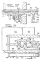
barrel cam 72, which is spaced rearwardly of thecam 70, has acam track 130 in which rides acam follower 13? fixed to alever 134 which is pivoted intermediate its ends in aclevis 136 secured to therear plate 138 of theframe 40 on apivot pin 140 provided with an eccentric mounting 142 which can be rotated to adjust the throw of thelink 134. The end of thelever 134 remote from thecam follower 132 is pivoted at 144 to alink 146, which is in turn pivoted to afeed slide 148 which carries thefeed pawl 21 and which is slidable in achannel 150 in afeed block 152. The strip 1? extends through astrip guide channel 151 in theblock 152. Thepawl 21 is urged towards thestrip 12 by aspring 147. Astrip drag plate 154 loaded by aspring 159 and engaging the strip 12 (Figure 9A) can be lifted by means of ahandle 158 to allow afresh strip 12 to be inserted into thechannel 151. As thecam 72 rotates through one revolution, thelink 134 drives theslide 148 and thus thefeed pawl 21 through a return stroke to take up thenext post 22 to be delivered to the severingstation 24 and through a feed stroke in which thefeed pawl 21 drives the post between theopen jaws station 24. Thedrag plate 154 prevents return movement of thestrip 12 during the return stroke of theslide 148. - The lower part of the apparatus, which is located beneath the X-Y table 4, will now be described with reference to Figures 7 and 7A. This part of the apparatus comprises a
frame 160 to which is mounted a further steppingmotor 162 on aplate 164 secured to theplate 160. Theshaft 166 of themotor 122 is connected by means of atoothed belt 168 of a synthetic rubber material to afurther disc cam 170 which is mounted on acamshaft 172 rotatably mounted in theframe 160, thecam 170 having acam track 174 in which rides acam follower 176 pivotally connected to alink 178 intermediate the ends thereof. The right-hand, as seen in Figure 7, end of thelink 178 is pivoted to theframe 160 at 180, the opposite end of thelink 178 being pivoted to one end of afurther link 182 at 184. The other end of thelink 182 is pivoted to aslide 186 at 188, which slide carries the supportingtool 134 and is slidable betweengibs 187. As thecam 170 is rotated by themotor 162 in the direction of the arrow J in Figure 7, thetool 34 is moved by theslide 186 between its retracted position and its board supporting position in the manner described with reference to Figures 2 to 5. Theshaft 172 is connected to anabsolute encoder 190, which continuously measures the angular position of theshaft 172. Thebelt 168 is engaged about asprocket wheel 192 on themotor shaft 166 and asprocket wheel 194 on thecamshaft 172. The motion of theslide 186 is indicated by the arrows K in Figure 7, the motion of thepivot point 184 being indicated by the arrow L in Figure 7. - Figure 11 is a timing diagram which indicates how the tooling described above is synchronized by means of the cam tracks, this tooling as a lot being synchronized electronically. In Figure 11, the angular positions of the
camshafts post 22a into thehole 32, the insertion of the post beginning at broken line M and full insertion being indicated by broken line N. As the insertion tool is being retracted towards its uppermost position, the roller 100 (cam track 76) begins to open thejaw 30, which is fully opened, for a dwell period, shortly after the insertion tool reaches its fully raised position. Whilst thejaw 30 is still in its open position, the feed pawl 21 (cam track 130) advances thestrip 12 so that the leading post is positioned at the severingstation 24, after which thejaw 30 is closed so that theJaws jaw 30 having dwelt in its open position during the greater part of the feed stroke of thepawl 21 which dwells in its fully advanced position during the strip severing operation. As thejaw 30 is closed, the die 28 (cam track 104) is advanced against thecarrier strip 20 and dwells in such position whilst the punch 26 (cam track 106) severs the carrier strip as indicated by the broken lines P and Q, after which the insertion tool descends again. As mentioned above, the board supporting tool 34 (cam track 174) is moved to its advanced, supporting, position prior to the insertion of the post into thehole 32 and is then retracted to allow the X-Y table to be indexed, following a dwell period during the insertion operation. - Figure 12 is a block schematic diagram of the
control unit 16 for theapparatus 2. Certain parts of the unit are duplicated to allow for the case where the apparatus is provided with dual insertion tooling for operation with the same X-Y table. The reference numerals of the duplicated parts are indicated by a prime symbol. In Figure 12, items not previously referred to are referenced as follows: a central microprocessor is referenced MP, miscellaneous sensors are referenced MS, indexers in the form of indexing pulse transmitters for the stepping motors as 1, drivers for the motors as D, head code means as HC, and a synchronizing control device for the X-Y table as CNC. The miscellaneous sensors MS, which are for the pre-inspection of thestrip 12, are arranged in the feed track for the detection of a splice or overlap in thestrip 12, a post that protrudes from the plane of thestrip 12, and the exhaustion of the supply of thestrip 12, and for other desired inspection purposes. - The
encoders shafts motors - The head code means is an electrical connector which has been jumpered to select a desired program for the operation of the apparatus from the memory of the microprocessor and the appropriate angular positions of the
shaft 54 for the program. There is no head code means for themotor 162, because the program for theshaft 54 dominates. The head code means may also indicate to the microprocessor as to whether the encoders are properly connected to the control circuit. - The computer numeric control CNC for the X-Y table is connected by a "hand shaking" line to the microprocessor MP for the synchronization of the operation of the
apparatus 2 and that of the X-Y table. - The pulse transmitter I supplies the stepping
motors motors apparatus 2. - A pulse divider PD may be interposed between the I and one of the motors if the number of pulses required by that motor is different from that required by the other.
- The
cathode ray display 15 indicates data relevant to the operation of the apparatus, under the control of the microprocessor. - The microprocessor receives data from the miscellaneous sensors, the head code, the
encoders control panel 17. - On the
control panel 17 are a number of, e.g., five, pushbuttons, the function of which will depend on the information displayed on thedisplay 15. For example, according to the information displayed, a pushbutton may become a start button, or a "jog" button, or a stop button, or it may become a means of answering a question posed on the display. - When a main machine start button 19 on the
unit 18 is pressed, the microprocessor MP compares data from its own memory as determined by the head code means HC with that supplied by theencoders shafts motors shaft ray tube display 15. If this should occur, the display instructs the operator which button on thepanel 17 to press in order to return theshafts apparatus 2 is ready to be started. - The
motors ray tube display 15 as well as instructions for clearing the fault. - If the microprocessor receives error data whilst the
apparatus 2 is In operation, it deactivates the transmitter I and thus the stepping motors, and the fault is indicated on the cathoderay tube display 15. - Although the above described embodiment employs an alternating current stepping motor having open loop feedback, the camshaft positions being checked by means of encoders, a DC servomotor or other closed loop drive may otherwise be employed. This could use the pulses emitted by an indexer or a resolver tachometer to provide feedback for motor synchronization.
Claims (12)
Applications Claiming Priority (2)
| Application Number | Priority Date | Filing Date | Title |
|---|---|---|---|
| US06/582,996 US4551901A (en) | 1984-02-24 | 1984-02-24 | Component insertion apparatus |
| US582996 | 1984-02-24 |
Publications (2)
| Publication Number | Publication Date |
|---|---|
| EP0156457A1 true EP0156457A1 (en) | 1985-10-02 |
| EP0156457B1 EP0156457B1 (en) | 1988-06-08 |
Family
ID=24331263
Family Applications (1)
| Application Number | Title | Priority Date | Filing Date |
|---|---|---|---|
| EP85300532A Expired EP0156457B1 (en) | 1984-02-24 | 1985-01-25 | Component insertion apparatus |
Country Status (7)
| Country | Link |
|---|---|
| US (1) | US4551901A (en) |
| EP (1) | EP0156457B1 (en) |
| JP (1) | JPS60206100A (en) |
| BR (1) | BR8500632A (en) |
| DE (1) | DE3563297D1 (en) |
| ES (1) | ES8602469A1 (en) |
| MX (1) | MX157677A (en) |
Cited By (5)
| Publication number | Priority date | Publication date | Assignee | Title |
|---|---|---|---|---|
| WO1986006557A1 (en) * | 1985-04-26 | 1986-11-06 | Amp Incorporated | Component insertion apparatus |
| WO2007125014A1 (en) * | 2006-05-02 | 2007-11-08 | Siemens Aktiengesellschaft | Component feeder |
| DE102008051525A1 (en) * | 2008-10-13 | 2010-04-15 | Tyco Electronics Amp Gmbh | Device and method for automatic loading of electrical components with contact elements |
| CN107437717A (en) * | 2016-07-20 | 2017-12-05 | 天泽精密技术(上海)有限公司 | Z-type terminal high speed contact pin mechanism |
| EP3254344A4 (en) * | 2015-02-04 | 2018-09-26 | ZionTECH Pte Ltd | Assembly apparatus |
Families Citing this family (14)
| Publication number | Priority date | Publication date | Assignee | Title |
|---|---|---|---|---|
| JPS61156800A (en) * | 1984-12-28 | 1986-07-16 | 富士通株式会社 | Connector pin inserter |
| US4720906A (en) * | 1985-09-23 | 1988-01-26 | Rca Corporation | Pneumatic insulation displacement terminal wire insertion tool |
| US4762507A (en) * | 1987-04-24 | 1988-08-09 | Amp Incorporated | Electrical contact retention system, and tool for removal and method therefor |
| US5095609A (en) * | 1990-03-29 | 1992-03-17 | Amp Incorporated | Work piece assembly machine |
| US5008999A (en) * | 1990-03-29 | 1991-04-23 | Amp Incorporated | Method of assembling components to electrical terminals |
| US5142765A (en) * | 1990-12-07 | 1992-09-01 | Rohm Co., Ltd. | Lead mounting apparatus |
| US5605430A (en) * | 1994-02-15 | 1997-02-25 | Zierick Manufacturing Corporation | Feeder and method of supplying a continuous strip of surface mount contacts to surface mounting equipment |
| DE19618481C1 (en) * | 1996-05-08 | 1997-08-14 | Telefunken Microelectron | Manufacture of electronic module with plug contacts and conducting cover cap |
| US5813108A (en) * | 1996-11-15 | 1998-09-29 | The Whitaker Corporation | Terminal insertion machine having improved shearing mechanism |
| US5899757A (en) * | 1997-11-03 | 1999-05-04 | Intercon Systems, Inc. | Compression connector |
| CN107611744A (en) * | 2017-09-06 | 2018-01-19 | 怡得乐电子(杭州)有限公司 | A kind of automotive connector terminal cuts off contact pin apparatus |
| CN108724310A (en) * | 2018-07-03 | 2018-11-02 | 杨真 | A kind of extruding cutting type plastic pipe cutting device |
| CN113285295B (en) * | 2021-06-08 | 2023-05-12 | 苏州华兴欧立通自动化科技有限公司 | Streamline type automatic jacking plug structure |
| CN113904197B (en) * | 2021-10-20 | 2024-02-23 | 长城电源技术(广西)有限公司 | Full-automatic precision terminal assembly mechanism |
Citations (5)
| Publication number | Priority date | Publication date | Assignee | Title |
|---|---|---|---|---|
| US4177549A (en) * | 1977-03-22 | 1979-12-11 | Matsushita Electric Industrial Company, Limited | Machine for mounting electrical components onto printed-circuit boards |
| GB2036611A (en) * | 1978-12-15 | 1980-07-02 | Gen Staple Co | Inserting terminals into a printed circuit board |
| EP0014940A1 (en) * | 1979-02-14 | 1980-09-03 | Matsushita Electric Industrial Co., Ltd. | Component inserting apparatus |
| US4365398A (en) * | 1978-11-30 | 1982-12-28 | Western Electric Company, Inc. | Method of and apparatus for assembling intermediate-web held terminal pins |
| US4403390A (en) * | 1978-10-31 | 1983-09-13 | Usm Corporation | Radial lead inserting machine |
Family Cites Families (11)
| Publication number | Priority date | Publication date | Assignee | Title |
|---|---|---|---|---|
| US3276653A (en) * | 1964-08-24 | 1966-10-04 | Amp Inc | Contact inserting apparatus |
| US3605237A (en) * | 1969-08-25 | 1971-09-20 | Berg Electronics Inc | Applicator for mounting wire wrap pins on circuit boards |
| US3820218A (en) * | 1973-02-14 | 1974-06-28 | Amp Inc | Terminal inserting apparatus |
| US3907008A (en) * | 1974-08-29 | 1975-09-23 | Universal Instruments Corp | Insertion apparatus |
| US3975811A (en) * | 1974-10-30 | 1976-08-24 | General Staple Company, Inc. | Autotab machine |
| JPS5419177A (en) * | 1977-07-12 | 1979-02-13 | Matsushita Electric Ind Co Ltd | Automatic electronic parts mounting device |
| JPS54126962A (en) * | 1978-03-24 | 1979-10-02 | Fuji Machine Mfg | Method of and apparatus for inserting electronic components into printed board |
| JPS54144974A (en) * | 1978-05-02 | 1979-11-12 | Tdk Electronics Co Ltd | Automatic electronic component insertion apparatus |
| JPS5626493A (en) * | 1980-03-17 | 1981-03-14 | Matsushita Electric Ind Co Ltd | Device for inserting electric part |
| US4429456A (en) * | 1982-02-01 | 1984-02-07 | Irwin Zahn | Apparatus for inserting elements into a workpiece |
| JPS60143496A (en) * | 1983-12-29 | 1985-07-29 | Fujitsu Ltd | Semiconductor storage device |
-
1984
- 1984-02-24 US US06/582,996 patent/US4551901A/en not_active Expired - Lifetime
-
1985
- 1985-01-25 DE DE8585300532T patent/DE3563297D1/en not_active Expired
- 1985-01-25 EP EP85300532A patent/EP0156457B1/en not_active Expired
- 1985-02-12 BR BR8500632A patent/BR8500632A/en not_active IP Right Cessation
- 1985-02-22 JP JP60034265A patent/JPS60206100A/en active Granted
- 1985-02-22 ES ES540630A patent/ES8602469A1/en not_active Expired
- 1985-02-22 MX MX204411A patent/MX157677A/en unknown
Patent Citations (5)
| Publication number | Priority date | Publication date | Assignee | Title |
|---|---|---|---|---|
| US4177549A (en) * | 1977-03-22 | 1979-12-11 | Matsushita Electric Industrial Company, Limited | Machine for mounting electrical components onto printed-circuit boards |
| US4403390A (en) * | 1978-10-31 | 1983-09-13 | Usm Corporation | Radial lead inserting machine |
| US4365398A (en) * | 1978-11-30 | 1982-12-28 | Western Electric Company, Inc. | Method of and apparatus for assembling intermediate-web held terminal pins |
| GB2036611A (en) * | 1978-12-15 | 1980-07-02 | Gen Staple Co | Inserting terminals into a printed circuit board |
| EP0014940A1 (en) * | 1979-02-14 | 1980-09-03 | Matsushita Electric Industrial Co., Ltd. | Component inserting apparatus |
Cited By (5)
| Publication number | Priority date | Publication date | Assignee | Title |
|---|---|---|---|---|
| WO1986006557A1 (en) * | 1985-04-26 | 1986-11-06 | Amp Incorporated | Component insertion apparatus |
| WO2007125014A1 (en) * | 2006-05-02 | 2007-11-08 | Siemens Aktiengesellschaft | Component feeder |
| DE102008051525A1 (en) * | 2008-10-13 | 2010-04-15 | Tyco Electronics Amp Gmbh | Device and method for automatic loading of electrical components with contact elements |
| EP3254344A4 (en) * | 2015-02-04 | 2018-09-26 | ZionTECH Pte Ltd | Assembly apparatus |
| CN107437717A (en) * | 2016-07-20 | 2017-12-05 | 天泽精密技术(上海)有限公司 | Z-type terminal high speed contact pin mechanism |
Also Published As
| Publication number | Publication date |
|---|---|
| BR8500632A (en) | 1985-10-01 |
| US4551901A (en) | 1985-11-12 |
| MX157677A (en) | 1988-12-08 |
| DE3563297D1 (en) | 1988-07-14 |
| ES540630A0 (en) | 1985-12-01 |
| ES8602469A1 (en) | 1985-12-01 |
| EP0156457B1 (en) | 1988-06-08 |
| JPS60206100A (en) | 1985-10-17 |
| JPH0339391B2 (en) | 1991-06-13 |
Similar Documents
| Publication | Publication Date | Title |
|---|---|---|
| EP0156457B1 (en) | Component insertion apparatus | |
| CA1135483A (en) | Radial lead inserting machine | |
| US4329776A (en) | Component inserting apparatus | |
| CA1056512A (en) | Machine for affixing circuit elements to printed circuit boards | |
| US4209898A (en) | Assembly line for parts of electronic and other equipments | |
| US4819699A (en) | Cartridge feed system for automatic PCB loading machine | |
| US4612700A (en) | Component insertion apparatus | |
| GB2174626A (en) | Wire feeding, cutting and stripping apparatus | |
| US4197637A (en) | Automated assembly apparatus for printed circuit boards | |
| JPH11135985A (en) | Method and device for supplying electric component and electric component mounting device | |
| US3852865A (en) | Semi automatic electronic component assembler | |
| US3539086A (en) | Multi size variable center electronic component insertion machine | |
| US4403390A (en) | Radial lead inserting machine | |
| US3796363A (en) | Multiple component insertion apparatus | |
| US3740817A (en) | Component insertion system for circuit boards | |
| US4603611A (en) | Feed system for punch press | |
| US2908010A (en) | Insertion machine | |
| EP0005468B1 (en) | Machine for automatically inserting parallel lead electronic components into a printed circuit board | |
| US4166312A (en) | Apparatus for re-forming an axial lead of an electronic component into U-shape and affixing said component to elongated support tape | |
| EP0195086A1 (en) | Automatic electronic part-inserting apparatus | |
| GB806523A (en) | Improvements in apparatus for assembling electrical components on component receiving parts | |
| US4370804A (en) | Electronic component inserting apparatus | |
| US4409733A (en) | Means and method for processing integrated circuit element | |
| US3859707A (en) | Electronic component semi-automatic assembly machine | |
| EP0438854B1 (en) | A press |
Legal Events
| Date | Code | Title | Description |
|---|---|---|---|
| PUAI | Public reference made under article 153(3) epc to a published international application that has entered the european phase |
Free format text: ORIGINAL CODE: 0009012 |
|
| AK | Designated contracting states |
Designated state(s): BE CH DE FR GB IT LI NL SE |
|
| 17P | Request for examination filed |
Effective date: 19860221 |
|
| 17Q | First examination report despatched |
Effective date: 19870811 |
|
| ITF | It: translation for a ep patent filed |
Owner name: BARZANO' E ZANARDO MILANO S.P.A. |
|
| GRAA | (expected) grant |
Free format text: ORIGINAL CODE: 0009210 |
|
| AK | Designated contracting states |
Kind code of ref document: B1 Designated state(s): BE CH DE FR GB IT LI NL SE |
|
| PG25 | Lapsed in a contracting state [announced via postgrant information from national office to epo] |
Ref country code: NL Effective date: 19880608 |
|
| PG25 | Lapsed in a contracting state [announced via postgrant information from national office to epo] |
Ref country code: SE Effective date: 19880630 |
|
| REF | Corresponds to: |
Ref document number: 3563297 Country of ref document: DE Date of ref document: 19880714 |
|
| ET | Fr: translation filed | ||
| NLV1 | Nl: lapsed or annulled due to failure to fulfill the requirements of art. 29p and 29m of the patents act | ||
| PLBE | No opposition filed within time limit |
Free format text: ORIGINAL CODE: 0009261 |
|
| STAA | Information on the status of an ep patent application or granted ep patent |
Free format text: STATUS: NO OPPOSITION FILED WITHIN TIME LIMIT |
|
| 26N | No opposition filed | ||
| ITTA | It: last paid annual fee | ||
| REG | Reference to a national code |
Ref country code: GB Ref legal event code: 732E |
|
| PGFP | Annual fee paid to national office [announced via postgrant information from national office to epo] |
Ref country code: BE Payment date: 19960207 Year of fee payment: 12 |
|
| PG25 | Lapsed in a contracting state [announced via postgrant information from national office to epo] |
Ref country code: BE Effective date: 19970131 |
|
| BERE | Be: lapsed |
Owner name: AMP INC. (UNE SOC. DE PENNSYLVANIE) Effective date: 19970131 |
|
| PGFP | Annual fee paid to national office [announced via postgrant information from national office to epo] |
Ref country code: GB Payment date: 19981211 Year of fee payment: 15 |
|
| PGFP | Annual fee paid to national office [announced via postgrant information from national office to epo] |
Ref country code: FR Payment date: 19990107 Year of fee payment: 15 |
|
| PGFP | Annual fee paid to national office [announced via postgrant information from national office to epo] |
Ref country code: DE Payment date: 19990128 Year of fee payment: 15 |
|
| PGFP | Annual fee paid to national office [announced via postgrant information from national office to epo] |
Ref country code: CH Payment date: 19990422 Year of fee payment: 15 |
|
| PG25 | Lapsed in a contracting state [announced via postgrant information from national office to epo] |
Ref country code: GB Free format text: LAPSE BECAUSE OF NON-PAYMENT OF DUE FEES Effective date: 20000125 |
|
| PG25 | Lapsed in a contracting state [announced via postgrant information from national office to epo] |
Ref country code: LI Free format text: LAPSE BECAUSE OF NON-PAYMENT OF DUE FEES Effective date: 20000131 Ref country code: CH Free format text: LAPSE BECAUSE OF NON-PAYMENT OF DUE FEES Effective date: 20000131 |
|
| GBPC | Gb: european patent ceased through non-payment of renewal fee |
Effective date: 20000125 |
|
| REG | Reference to a national code |
Ref country code: CH Ref legal event code: PL |
|
| PG25 | Lapsed in a contracting state [announced via postgrant information from national office to epo] |
Ref country code: FR Free format text: LAPSE BECAUSE OF NON-PAYMENT OF DUE FEES Effective date: 20000929 |
|
| PG25 | Lapsed in a contracting state [announced via postgrant information from national office to epo] |
Ref country code: DE Free format text: LAPSE BECAUSE OF NON-PAYMENT OF DUE FEES Effective date: 20001101 |
|
| REG | Reference to a national code |
Ref country code: FR Ref legal event code: ST |