EP0155815A2 - Elektrische Muskelreizung - Google Patents
Elektrische Muskelreizung Download PDFInfo
- Publication number
- EP0155815A2 EP0155815A2 EP85301736A EP85301736A EP0155815A2 EP 0155815 A2 EP0155815 A2 EP 0155815A2 EP 85301736 A EP85301736 A EP 85301736A EP 85301736 A EP85301736 A EP 85301736A EP 0155815 A2 EP0155815 A2 EP 0155815A2
- Authority
- EP
- European Patent Office
- Prior art keywords
- muscle
- pulse
- pulses
- sequence
- data
- Prior art date
- Legal status (The legal status is an assumption and is not a legal conclusion. Google has not performed a legal analysis and makes no representation as to the accuracy of the status listed.)
- Withdrawn
Links
Images


Classifications
-
- A—HUMAN NECESSITIES
- A61—MEDICAL OR VETERINARY SCIENCE; HYGIENE
- A61N—ELECTROTHERAPY; MAGNETOTHERAPY; RADIATION THERAPY; ULTRASOUND THERAPY
- A61N1/00—Electrotherapy; Circuits therefor
- A61N1/18—Applying electric currents by contact electrodes
- A61N1/32—Applying electric currents by contact electrodes alternating or intermittent currents
- A61N1/36—Applying electric currents by contact electrodes alternating or intermittent currents for stimulation
- A61N1/36003—Applying electric currents by contact electrodes alternating or intermittent currents for stimulation of motor muscles, e.g. for walking assistance
-
- A—HUMAN NECESSITIES
- A61—MEDICAL OR VETERINARY SCIENCE; HYGIENE
- A61N—ELECTROTHERAPY; MAGNETOTHERAPY; RADIATION THERAPY; ULTRASOUND THERAPY
- A61N1/00—Electrotherapy; Circuits therefor
- A61N1/18—Applying electric currents by contact electrodes
- A61N1/32—Applying electric currents by contact electrodes alternating or intermittent currents
- A61N1/36—Applying electric currents by contact electrodes alternating or intermittent currents for stimulation
- A61N1/36014—External stimulators, e.g. with patch electrodes
- A61N1/3603—Control systems
- A61N1/36034—Control systems specified by the stimulation parameters
-
- A—HUMAN NECESSITIES
- A61—MEDICAL OR VETERINARY SCIENCE; HYGIENE
- A61N—ELECTROTHERAPY; MAGNETOTHERAPY; RADIATION THERAPY; ULTRASOUND THERAPY
- A61N1/00—Electrotherapy; Circuits therefor
- A61N1/18—Applying electric currents by contact electrodes
- A61N1/32—Applying electric currents by contact electrodes alternating or intermittent currents
- A61N1/36—Applying electric currents by contact electrodes alternating or intermittent currents for stimulation
- A61N1/36014—External stimulators, e.g. with patch electrodes
- A61N1/3603—Control systems
- A61N1/36031—Control systems using physiological parameters for adjustment
Definitions
- the present invention relates to the electrical stimulation of muscles and to electromyographic techniques useful for acquiring information to improve such muscle stimulation.
- Faradic stimulation has generally proceeded on the basis of applying to muscle, usually by a number of electrodes overlying the muscle or muscles in question, an electrical signal to produce a mechanical response in the fibres of the muscle intended to be similar, on qualitative and approximate assessment to that caused by the fibres' stimulation by associated motor neurons.
- the electrical signal has usually been a pulse train, having uniform characteristics in terms of pulse length and pulse separation, intended to stimulate the fibres in a manner similar to their stimulation by their associated motor neurons.
- Such a pulse train, properly applied, produces contraction of the muscle fibres resulting in mechanical action.
- a first aspect of this invention is concerned with examining more closely than has hitherto been possible without physical dissection of the muscle or invasion of its substance, the information contained in the time series represented by the discharge of individual motor unit action potentials ( M UAP's for short) generated as a result of normal neurone control of movements.
- a first aspect of the invention provides a method of acquiring data comprising an amplitude-independent temporal sequence of muscular motor unit action potentials, such method comprising obtaining electromyographic signals from a muscle or muscle group and processing the signals to extract characteristic signals relating to one or more individual motor units and further processing the extracted signals to derive said data.
- This aspect of the invention also provides apparatus for acquiring data comprising an amplitude - independent temporal sequence of muscular motor unit action potentials comprising means for obtaining electromygraphic signals from a muscle or muscle group and means for extracting from the obtained signals, unique signals relating to one or more individual motor units and means for processing the extracted signals to derive said data.
- this aspect of the invention can provide a non-invasive technique for studying information conveyed by MUAPs.
- This aspect of the invention is concerned with the fact that, by a refined and discriminating recording technique and by suitable signal processing techniques, one can extract from the recorded electromyographic response of a muscle, which usually comprises MUAPs associated with a multiplicity of motor units, the MUAPs associated with individual motor units.
- a muscle which usually comprises MUAPs associated with a multiplicity of motor units
- the MUAPs associated with individual motor units This may be achieved, for example, by pulse height and pulse shape analysis of individual pulses making up the electromyogram.
- the signal processing involves pulse height analysis, since it has been found that by defining a suitably narrow pulse height detection window (of 12 microvolts in one practical example), MUAPs associated with individual motor units can be monitored.
- apparatus for applying stimulating pulses to muscle fibre comprising pulse generating means and at least one pair of electrodes for applying a sequence of pulses generated thereby to the muscle fibre, or to overlying tissue, the pulse generator being so adapted that the pulse sequence conveys electrotrophic information for causing desired structural and/or functional adaptation of the muscle fibre.
- This aspect of the invention also provides a method of applying stimulating pulses to muscle fibre comprising generating and applying fibres or to overlying tissue a stimulus pulse sequence being so selected that the pulse sequence conveys electrotrophic information for causing a desired structural and/or functional adaptation of muscle fibre and of which a muscle is comprised and applying said sequence of pulses to the muscle, or to overlying tissue.
- the second element of information is believed to initiate and control functional adaptation of the muscle fibre.
- This second element can be identified from the difference in discharge patterns in muscles adapted to one form of muscle activity and the same muscles adapting to another where, for example, an anabolic "body-building" procedure is taking place.
- the information conveyed by this code is by no means fully understood. Nevertheless it can be copied and transcribed and so used to define a pulse sequence for use in muscle stimulation with a view to allevating muscular disfunction and/or otherwise "re-educating" muscles to produce medium and long term beneficial effects by effecting a long lasting metabolic change in the muscle being treated which manifests itself by its contractile properties.
- a third aspect of the invention provides apparatus for applying stimulating pulses to muscle fibre comprising pulse generating means and at least one pair of electrodes for applying a sequence of pulses generated thereby to the muscle fibre, or to overlying tissue, the pulse generator being so adapted that the intervals between respective stimulating pulses in a sequence of pulses can be individually defined.
- the second aspect of the invention further provide a method of generating a sequence of muscle stimulating pulses in accordance with pulse interval data held a memory comprising the steps of
- steps (A) to (E) inclusive being executed for each of a series of items of pulse interval data.
- step (B) the contents of the memory location are initialized with the value of the item of pulse interval data and wherein the loop from step (D) to step (E) is exited when said contents have a predetermined value.
- a plurality of channels of stimulating pulses may be produced, in which case steps (A) to (E) inclusive may be carried out for each channel, corresponding steps for each channel being carried out in succession.
- a check may be carried out to establish if the pulse should be produced, and the pulse inhibited if it should not e.g. because no pulse is required at that time, or a hardware or software fault is detected.
- electrotrophic stimulation may be combined, preferably in a non-overlapping manner time-wise, with functional stimulation to provide a treatment procedure for regenerating muscle and/or improving its performance.
- this aspect of the invention also provides apparatus for applying stimulating pulses to muscle fibre comprising pulse generating means and at least one pair of electrodes for applying a sequence of pulses generated thereby to the muscle fibre, or to overlying tissue, the pulse generator being so adapted as selectively to produce, as said pulse sequence, a pulse sequence conveying electrotrophic information for causing desired structural and/or functional adaptation of the muscle fibre or a pulse sequence conveying functional stimulation information.
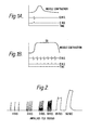
- Figure 1B shows 50 stimuli per second generating a mechanical response with the whole effect fusing. Note that the electrical effects in the nerve (ENG) and muscle (EMG) are still separate.
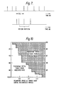
- the upper trace in Figure 3A shows a time marker, (10, 50, 100 milliseconds) the middle trace an electromyogram, of human facial muscles and the lower trace, integrated electrical signal of the discharge.
- the "window” can be set to a very small voltage. In Figure 4A it is 12 microvolts. It may be moved through the electromyogram, so dissecting electrically the discharge pattern.
- Figures 4B and 4C are very high resolution records taken from the facial muscles showing how accurately the motor unit action potential peaks can be isolated and detected.
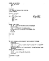
- FIG. 5 shows in block form one version of electromyographic apparatus in accordance with the first aspect of the present invention, which makes use of this technique.
- the apparatus 1 comprises a sensitive, low noise differential amplifier and filter 3 which is used to amplify the elqctromyographic signal appearing across two electrodes 5 which may be of the type conventionally used in electromyography.
- the output of the amplifier 3 is recorded onto one channel of a magnetic tape data recorder 4, a 5kHz timing marker signal from a reference oscillator 10 being reroded on the other channel.
- the output of the first channel is applied to the input of a window comparator 6 which compares the instantaneous amplitude of the signal with upper and lower threshold values separated by a sufficiently small voltage (say, 12 microvolts) so that the peaks of only MUAPs associated with one particular motor unit will fall within the comparison window.
- a window comparator 6 which compares the instantaneous amplitude of the signal with upper and lower threshold values separated by a sufficiently small voltage (say, 12 microvolts) so that the peaks of only MUAPs associated with one particular motor unit will fall within the comparison window.
- the window comparator has two logical outputs, 7 and 8 which change state respectively when the lower and upper window levels are exceeded. These outputs are applied via a suitable interface (not shown) to a suitably programmed microcomputer 9 which also receives the reproduced timing signal so that the timing of the transitions of the outputs 7 and 8 of the window comparator 6 may be established.
- the window comparator is provided with a user-operable control such as potentiometer 7 allowing the threshold levels at which transitions of the outputs 7 and 8 take place to be shifted, while maintaining the desired difference between these levels.
- a further control, not shown, may also be provided to adjust the height of the detection window.
- the microprocessor monitors the outputs 7 and 8. Each time a positive-going transition of the lower threshold output 7 occurs, the microprocessor 9 stores the current time indicated by the real time clock 10. If and only if the transition of the output 7 is not followed within a defined time period by a positive going transition of the upper threshold output 8, (this condition indicating that the peak of a motor unit action potential fell within the detection window) the read out clock value is stored as relating to a MUAP. Otherwise it is disgarded.
- the microcomputer 9 can thus record the relative timing of a series of MUAPs associated with an individual motor unit and to calculate both the mean frequency of discharge and the instantaneous frequency, that is the frequency corresponding to the interval between successive discharges. It will be appreciated that in real-time applications, the data recorder 4 is superfluous and the outputs of the amplifier 3 and clock 10 are applied directly to the microcomputer 9.
- Standard hardware may be used to implement the apparatus shown in Figure 5.
- the amplifier/filter 3 may be constituted by Neurolog. NLI03 and NLl15 units sold by Digitimer Ltd
- the data recorder 4 may be of the type DA1442/Q/4/1 sold by Data Aquistion Ltd
- the window comparator 6 may be the Digitimer Ltd D130 spike discriminator and detector logic unit
- the clock 10 may be constituted by a DI13 A/D converter made by Interactive Structures Inc which can provide an Apple-compatible clock signal.
- Skeletal muscle has the ability to adapt its molecular form to better meet functional requirements, that is to say muscle is plastic. It exists in a highly dynamic equilibrium where there is constant breakdown (catabolism) of the molecules which characterise muscular action (eg the enzymes associated with the contractile protein myosin, and those which play a role in the energy metabolism). The equilibrium is maintained by biosynthesis of replacement enzyme molecules (anabolism).
- catabolism the molecules which characterise muscular action
- the equilibrium is maintained by biosynthesis of replacement enzyme molecules (anabolism).
- the contact normal nerve makes with normal muscle exerts a "trophic control" on the muscle at rest.
- the control is unrelated to the impulse traffic transmitted by the nerve to the muscle.
- the definition is now somewhat qualified the action is still within that sphere.
- neurotrophic action maintains, for example, the integrity and effectiveness of the neuromuscular junction.
- Nerve transmits to muscle two simultaneous trains of information:
- the use of logical detection circuits allow discrimination and timing of the MUAPs generated during movement by normal subjects. From these pattern two contributory patterns can be extracted by computation. One is the dominant represented by the mean discharge frequency, the other is a signal which contributes to that mean but differs significantly from it. This contains the most potent component of the trophic code. It carries the signal CHANGE which comes in the command series:
- Muscular action elicited by low frequency, long duration activity is known to increase the fatigue resistance of muscle, and to induce it to capillarise with blood vessels. Short periods of high frequency bursts of electrical stimulation are less predictable in their action.
- the effect of the mean MUAP discharge frequency is having an effect, albeit only partial.
- the distinct signal of the trophic code can be seen in only incompletely understood action.
- the trophic code cannot at the present time be deciphered, but it can be copied and transcribed.
- a physiotherapist or clinician will be able to prescribe an individual electrotrophic therapy which will be dispensed by in the form of an I.C. or other storage device the appropriate trophic code.
- This action involves an expression of genes within the chromosomes of the muscle fibres. Understandably, this unlocking of the genetic potential of a muscle requires a very secure key system. If the response of the muscles is not to be a nonsense or a futile response a subtle code must be available to signal that the change to take place in the muscle will be purposeful and appropriate. This is the trophic code for the muscle.
- the response of skeletal muscle to either a naturally discharged nerve impulse or an electric stimulus shows several cyclic responses.
- the ion fluxes of the action potential which initiates mechanical action has a cycle time of the order of 1 millisecond.
- the "second messenger" release of AMP and its derivatives have an effective life cycle of 1.0s.
- MUAP motor unit action potentials
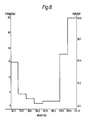
- a frequency distribution such as is shown in Figure 8 may be computed.
- the frequency of occurrence of i.s.i.s of the values contained in the sample width are drawn.
- Non-time series statistical procedural artefacts can be separated from information carrying MUAP discharge trains by randomising or "shuffling" the order of elements in the i.s.i. data file.
- a frequency distribution plot of the shuffled data elements is shown in Figure 9 and shows statistical comparability but the time sequence information has been lost.
- the unshuffled i.s.i. data file may be quantized by allocating the value 1 if the isi is between 5 ms, and 10 ms and the value 2 if it is between 5 and 10 ms....and so on.
- hypothesized "Potent Pattern” may be quantized and a computer search for the number of times it occurs during the time course of the data file a similar search is made of the "shuffled", randomized file for comparison.
- the digitization process may be carried out using an algorithm such as the following: start interspike interval isi(O) followed by i(l), i(2) togetheri(n).
- a suspected potent pattern comprises the sequence of i.s.i.s 2, 1, 3, 1. Then a search through the digitized unshuffled data file can be carried out to establish its frequency of occurrence; a similar search through the digitized shuffled file, will help identify whether the pattern is a significant time-series pattern.
- the effectiveness of the technique in establishing the "trophic code" may be increased by making the stages of MUAP detection, measurement and quantization at times when induced adaptation of normal muscle is occurring.
- Motor units can be recruited to action, each contributing its available force, and the available force can be amplified by increasing the rate at which the motor unit is excited and generates its force.
- Figure 10 illustrates this relationship for a hand muscle. As this represents the "signature" of the muscle in normal action and deviation from it during abnormality or rehabilitation reveals a factor involving the fequency of discharge of discharge with respect to recruitment and force development that refines the procedures of reasoning, analysis and computation described above.
- the above described window detection can be supplemented by the use of a single.
- detector beam which is stepped, by regular decrements in detection voltage, down through the signal.
- Computer files can then be established of the time intervals between the compound MUAP potentials detected each level, and software can then establish the code for the individual motor units by a subtraction routine operating on each of the files in turn; this can take into account the possibility of interference signals from the larger number of potentials.
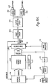
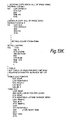
- FIG. llA shows one form of muscle stimulating apparatus according to the present invention.
- a memory device 100 which may be in the form a PROM (programmable read only memory) integrated circuit has stored therein data defining a pulse sequence on which is coded trophic information with which it is desired to stimulate a muscle or muscle group. This information is coded as the respective time intervals between successive pulses which are to be generated. This data is sequentially read out, and, in a manner to be described in more detail below, used to generate a train of fixed length pulses. The relative timing of the pulses, i.e. the intervals between successive pulses conveys the desired trophic information.
- PROM programmable read only memory
- This pulse train is applied to one or more output channels comprising a pulse conditioning circuit 103 which may, inter alia, buffer the signal produced and/or modulate the pulse waveform into a succession of bursts with spaces therebetween; the bursts may have a shaped envelope.
- the output of pulse conditioning circuit 103 is applied to an output stimulation circuit 105 which may incorporate a step up transformer and/or level control circuitry to transform the signal to the appropriate level for muscle stimulation and/or to define a desired source impedence for the stimulating signal.
- This stimulating signal is applied to two or more output electrodes 107 which are placed in contact with the skin overlying the muscle or muscle group of interest. Where there are more than two output electrodes, individual electrodes may have individual level controls such as the potentiometer 108 shown in Figure 13.
- the memory 100 may be paged, having a number of trophic codes which may be of different lengths, and in these circumstances a code selector 117 (e.g. a multi-position switch may be used to select the code to be generated).
- a code selector 117 e.g. a multi-position switch may be used to select the code to be generated.
- a power-on reset circuit 109 generates a pulse which is applied to the "clear" input of address counter 101.
- the address counter 101 generates an address signal which is applied to the memory 100 causing the contents of its first storage location on the selected page, representing a first pulse interval, to read out as data.
- This read-out data is applied to the "load" input of a down-counter 111 whose stored count then proceeds to be decremented by the application of clock pulses from an oscillator 113 having a frequency of, say, 1KHz. This gives a minimum interval of lmS. In this unit the interval between trophic code pulses is an integral number of milliseconds. Should higher resolution be necessary a higher frequency could be used;
- the "zero" pulse from the down-counter 111 also causes this read-out data to be loaded into the down counter 111, whose contents thereupon proceed to be decremented by the pulses from oscillator 113 resulting, after a time period defined by the value of the read-out data word in the application of a further pulse to the pulse conditioning circuit 103. This process repeats for each of the items of data stored in the memory 100.
- the desired sequence may be terminated by a pre-defined word value e.g. 000....
- a reset circuit 115 may be provided to detect the occurrence of this terminating word and apply a pulse to the "clear" input of the address counter 101 so that generation of the required pulse sequence recommences at that point.
- a variable delay block 116 may be provided to allow for an adjustable delay between successive generating cycles of the stored code. This can enable the pulses to be produced in spaced apart bursts.
- the stimulator 100 operates to generate a sequence of fixed length pulses, for application to the muscle/muscle group or overlying tissue, with intervals between successive pulses determined by the values of successive data words stored in memory 100. By appropriate selection of these intervals, the desired trophic information can be coded onto the pulse sequence applied via the electrodes 107 to produce a particular long term adaptation of the muscle/muscle group in question.
- the memory device 100 may be of any suitable form; conveniently it is a PROM (programmable read only memory) IC although any other suitable device such as a magnetic or optical disc, tape, RAM IC, bubble memory, shift register and so forth may be used - even a series of switches which can be set to one of a number of positions to define respective pulse intervals.
- the device may be such that the data read out can readily be changed so that trophic data for a variety of treatments can be used on a single stimulator 100 as selection of a different code stored in the memory 100, using the selector 117 or by user replacement of one PROM conveying particular trophic data by another. It is also possible, using a suitable read/write memory for the required data to be down loaded from a remote source e.g. via modem, local area network or any other suitable communications link, thereby enabling "treatment at a distance".
- a remote source e.g. via modem, local area network or any other suitable communications link
- the pulse conditioning circuit and the output stimulation circuit may be so designed to maximize the subcutaneous response but minimize the response of peripheral pain receptors. Thus prolonged application of stimuli should present no difficulty.
- the design of the output stimulation circuit is such that it basically acts as a very low impedence current source yet will limit the surface voltage should the load impedance increase excessively. This aspect of the design therefore prevents "biting" or "stinging” from electrodes being removed or repositioned during treatment.
- the pulse width and envelope shape are determined by the pulse-conditioning circuit and are selected so that current pulse rise-time, current pulse amplitude and current pulse-width provide maximum subcutaneous stimulation but avoid affecting the peripheral pain receptors. The exact values of these parameters depend on the size and charcteristics of the muscles being addressed. For example on small twitch muscle such as facial, the pulse-width parameter is usually set at approximately 80uS whereas for a larger muscle group (Quads) a pulse-width of 200uS may be used.
- Figure 11B is a circuit diagram showing one particular form the embodiment of Figure 11A may take. The following components may be used in the circuit of Figure 11B:-
- the circuitry shown in Figure 11 is one of many circuits which may be used to translate the stored data into the desired pulse train.
- the pulse generation could be achieved in software by a suitably programmed microprocessor reading the data defining the desired pulse sequence from a memory device such as a PROM or any of the others mentioned above, the microprocessor delivering from a suitable output a train of pulses for conditioning as by the circuits 103, 105 and application to the electrodes.
- patients could be issued with a machine-readable treatment card on which is recorded, or at least identified, the trophic data to be used for treatment; this card could also have in machine readable form details of the patients, the condition which is to be treated and so forth.
- the pulse conditioning circuit and the output stimulation circuit may be so designed to maximize the subcutaneous response but minimize the response of peripheral pain receptors. Thus prolonged application of stimuli should present no difficulty.
- the code generator unit may store within the code memory values to alter the stimulation pulse-width, stimulation pulse-amplitude, stimulation pulse rise and fall times.
- the code generator unit may store within the code memory values to alter the stimulation pulse-width, stimulation pulse-amplitude, stimulation pulse rise and fall times.
- a sensor element possibly electromyographic feeding information to a processing unit (microcomputer) programmed with appropriate digital filtering and signal processing algorithms, based on physiological parameters inputs which could adaptively alter the trophic code sequence to converge on a predefined physiological goal.
- a processing unit microcomputer programmed with appropriate digital filtering and signal processing algorithms, based on physiological parameters inputs which could adaptively alter the trophic code sequence to converge on a predefined physiological goal.
- a second embodiment of the invention shown in Figure 12 uses Apple II microcomputer 200 incorporating an output device in the form of a 6522 VIA (versatile interface adaptor) 201 installed in an option slot to output stimulating pulses as exemplified in Figures 14A and 14B.
- Apple II microcomputer 200 incorporating an output device in the form of a 6522 VIA (versatile interface adaptor) 201 installed in an option slot to output stimulating pulses as exemplified in Figures 14A and 14B.
- Both sides of the VIA are used for output, with positive going signals on the A-side output and negative going signals on the B side output.
- the A-side positive going pulses have been provided in case external amplification (and resulting signal inversion) are necessary.
- the software is not interrupt driven and interrupts are disabled.
- the synch mechanism just waits in a software loop until the timer has counted down to zero.
- the software has been developed for the Apple II computer in 6502 assembler, and these routines interface to the UCSD Pascal system of the Apple. This has facilitated the development of software for data entry and encoding of the files containing the profiles of the pulse sequences.
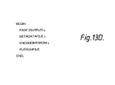
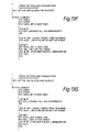
- One version of the software is shown in Figure 13.
- the output from the Apple will drive eight channels to an accuracy of 2 msec with a sequence of up to 63 pulses per channel.
- Each data word for the pulse routine has four attributes. These are a count, an encoded channel number, if a pulse is required (on the count ultimately reaching zero ⁇ and finally if the channel is on.
- the conditions required to output a pulse on a given channel are:-
- SETVIA sets up the VIA device for outputs on both the A- and B- sides.
- the A- side is initialised to zero volts (for +ve pulses) and the B- side is initialised high (between 4 and 5 volt TTL) for negative going pulses.
- This routine also sets the TIMER1 of the VIA in a free running mode to generate the synchronisation signal of 2 msec. Interrupts are disabled.
- the second routine PULSES services data from a file containing the encoded pulse trains.
- the encoded data is treated as if it were ROM and no attempt is made to modify it from within the PULSES routine.
- the PULSES routine uses PAGE ZERO locations of the Apple to maintain the counts required to output on each channel. On entry the current contents of PAGE ZERO are saved (to be restored on exit from the routine). The routine maintains a table of pointers into the ROM and also a table of values of the current counts for each channel.
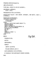
- the Pascal program ENCODE sets up the data files in the correct format for the PULSES machine code pulse generator routine.
- the data file is as follows
- the above described stimulator has been used in relation to Bell's palsy.
- the stimulation pattern consists of stimulation/relaxation cycles (1.45 on/1.45 off) at between 5 and 8Hz (stimuli per second), this being the frequency of firing adopted by normal facial muscles.
- trophic stimulation One development of the basic concept of trophic stimulation is that of summation stimulation.
- Adequate stimulation of mechanoceptors in muscle, with vibration for example, can be made to summate in effectiveness with electrical stimulation at a level subthreshold for independent excitation.
- the summation of the two forms of stimulation will be potent in generating reflex action in the spinal cord.
- the resulting reflex effect can be detected electromyographically from the surface of the affected muscles, the processed signal from that detection will interact with the computer controlling the two forms of stimulation, trophic and functional, to optimise both frequency and amplitude of the summating electrical and mechanical stimuli.
- Trophic stimulation as described above conditions the muscle's blood supply, its metabolism and the mechanical action to which the energetics of metabolism is applied.
- electrotrophic stimulation may be combined with functional stimulation to achieve a desired psysiological goal.
- Trophic stimulation on the other hand, is new, and when based on computations of the natural discharge patterns of motor units in the muscles involved, is termed eutrophic stimulation.
- a careful analysis of the condition of the muscle shows a reduction in the number of blood capillaries providing oxygen and nutrients for action, and the opportunity for eliminating from the muscle the metabolic products of that action and of work.
- Eutrophic stimulation by comparison, is calculated first to improve the muscle vascularisation without involving the muscle in self destructive activity. Simultaneously it improves the protein mass of the muscle and its effectiveness during muscular activity. It also reduces the susceptibility of the muscle to self-induced degeneration.
- the characteristics of stimuli needed in functional stimulation are set not by the natural firing frequency of motor units in the spinal cord, but by the need for an unnatural excitation lacking the subtelty of normal central nervous system control, designed to compel the muscle to apply force to the joints.
- Eutrophic stimulation can therfore be used to equip the muscle, in terms of its vascularisation, its dependent metabolism and mechanical action,- to act in response to and tolerate indefinitely the functional component of stimulation.
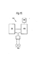
- FIG. 15 shows an embodiment of the invention for implementing a combined electrotrophic and functional stimulation procedure.
- the stimulator 151 comprises 3-channel electrotrophic stimulator 151, which may be in accordance with any of the above-described (or indeed, ay other) embodiments of the invention, a functional stimulator 152 and a set of stimulation electrodes 153 to which the output of one or other of the stimulators 151 and 152 is applied.
- the currently available stimulators can now be modified to mix both characteristics of stimulus and have them converge in effectiveness onto one electrode pair.
- the stimulator has two distinct stimulation modes.
- the three channels of the electrotrophic stimulator 151 will deliver separately eutrophic patterns of stimulation. These will be patient operated in that they can start and end the procedure of pattern stimulation. The repetition of patterns, with, say, two seconds on and two seconds off will probably have to last for at least six hours continuously a day.
- the three channels deliver to the muscle three evolving therapies to be changed during the first three months of use under the supervision of a clinician of physiotherapist. The conditioning of the muscle for functional stimulation will in this way be optimised.
- the second major mode of stimulation is functional and provided by the stimulator 152.
- the determination of timing and stimulus characteristics will depend on patient physique and disability, and upon what muscle function it is desirable to restore.
- the functional stimulator may be programmed by the output of an EMG device and by user input by the clinician. Suitable hardware and/or software is provided to give the required programmability.
- the functional stimulator may exert an inhibitory control over the electrotrophic stimulator, or the stimulator oututs may be otherwise arranged, so that the functional and trophic stimulators are not applied at the same time.
- the programmability of the stimulator will facilitate the tuning of the stimulator in the clinic. It will also make easy the re-tuning that will be required as the muscle adapts to use under stimulation conditions.
- the stimulator may be arranged so that functional stimulation is controlled intrinsically, in a manner tuned initially by the clinician, and eventually later in the treatment the functional stimulation is controlled by detection of EMG potentials or their integrated signal detected in muscles still functioning.
Applications Claiming Priority (2)
| Application Number | Priority Date | Filing Date | Title |
|---|---|---|---|
| GB848406509A GB8406509D0 (en) | 1984-03-13 | 1984-03-13 | Electrical stimulation of muscle |
| GB8406509 | 1984-03-13 |
Publications (2)
| Publication Number | Publication Date |
|---|---|
| EP0155815A2 true EP0155815A2 (de) | 1985-09-25 |
| EP0155815A3 EP0155815A3 (de) | 1986-06-25 |
Family
ID=10557995
Family Applications (1)
| Application Number | Title | Priority Date | Filing Date |
|---|---|---|---|
| EP85301736A Withdrawn EP0155815A3 (de) | 1984-03-13 | 1985-03-13 | Elektrische Muskelreizung |
Country Status (3)
| Country | Link |
|---|---|
| US (1) | US4712558A (de) |
| EP (1) | EP0155815A3 (de) |
| GB (2) | GB8406509D0 (de) |
Cited By (5)
| Publication number | Priority date | Publication date | Assignee | Title |
|---|---|---|---|---|
| EP0201271A2 (de) * | 1985-04-29 | 1986-11-12 | B.M.R. Research and Development Limited | Einrichtung zur Muskelstimulation |
| EP0459945B1 (de) * | 1990-05-26 | 1997-11-19 | MED-EL Medical Electronics Elektro-medizinische Geräte GmbH | Einrichtung zur neuromuskulären Elektroreizung |
| EP1455890A2 (de) * | 2001-11-27 | 2004-09-15 | Science Medicus, Inc. | Behandlung von asthma und atemwegserkrankungen durch elektrische neurorezeptive wellenformen |
| EP1478431A1 (de) * | 2002-02-28 | 2004-11-24 | Science Medicus, Inc. | Elektrisches verfahren zur kontrolle der autonomen nervenstimulation des magen-darm-kanals |
| US9775662B2 (en) | 2012-12-06 | 2017-10-03 | Ossur Hf | Electrical stimulation for orthopedic devices |
Families Citing this family (76)
| Publication number | Priority date | Publication date | Assignee | Title |
|---|---|---|---|---|
| US4957480A (en) * | 1988-02-02 | 1990-09-18 | Universal Health Products, Inc. | Method of facial toning |
| US4895154A (en) * | 1988-02-19 | 1990-01-23 | Staodynamics, Inc. | Electronic stimulating device for enhanced healing of soft tissue wounds |
| US5041974A (en) * | 1988-10-26 | 1991-08-20 | Walker Judith B | Multichannel stimulator for tuned stimulation |
| US5281219A (en) * | 1990-11-23 | 1994-01-25 | Medtronic, Inc. | Multiple stimulation electrodes |
| US5350415A (en) * | 1993-03-08 | 1994-09-27 | Jozef Cywinski | Device for trophic stimulation of muscles |
| US5458626A (en) * | 1993-12-27 | 1995-10-17 | Krause; Horst E. | Method of electrical nerve stimulation for acceleration of tissue healing |
| US6865423B2 (en) | 1996-06-13 | 2005-03-08 | The Victoria University Of Manchester | Stimulation of muscles |
| AU3180897A (en) | 1996-06-13 | 1998-01-07 | Victoria University Of Manchester, The | Stimulation of muscles |
| US5810747A (en) * | 1996-08-21 | 1998-09-22 | Interactive Remote Site Technology, Inc. | Remote site medical intervention system |
| GB2324965B (en) * | 1997-05-09 | 2001-05-23 | Mediwave Res Ltd | Muscle restructuring system |
| US6556869B1 (en) | 1999-12-01 | 2003-04-29 | Vertis Neuroscience, Inc. | Electrode introducer for a percutaneous electrical therapy system |
| US6912424B2 (en) * | 1999-12-01 | 2005-06-28 | Meagan, Medical, Inc. | Apparatus and method for coupling therapeutic and/or monitoring equipment to a patient |
| US6549810B1 (en) | 1999-12-01 | 2003-04-15 | Vertis Neuroscience, Inc. | Percutaneous electrical therapy system with electrode depth control |
| US6522927B1 (en) | 1999-12-01 | 2003-02-18 | Vertis Neuroscience, Inc. | Electrode assembly for a percutaneous electrical therapy system |
| US6493592B1 (en) | 1999-12-01 | 2002-12-10 | Vertis Neuroscience, Inc. | Percutaneous electrical therapy system with electrode position maintenance |
| US6539264B1 (en) | 1999-12-01 | 2003-03-25 | Vertis Neuroscience, Inc. | Percutaneous electrical therapy system with sharp point protection |
| US6516226B1 (en) | 1999-12-01 | 2003-02-04 | Vertis Neuroscience, Inc. | Percutaneous electrical therapy system for minimizing electrode insertion discomfort |
| US6529776B1 (en) | 1999-12-01 | 2003-03-04 | Vertis Neuroscience, Inc. | Method and apparatus for repositioning a percutaneous probe |
| US6622051B1 (en) | 1999-12-01 | 2003-09-16 | Vertis Neuroscience, Inc. | Percutaneous electrical therapy system with electrode entry angle control |
| US6560491B1 (en) | 1999-12-01 | 2003-05-06 | Vertis Neuroscience, Inc. | Percutaneous electrical therapy system providing electrode axial support |
| US6549797B1 (en) | 1999-12-01 | 2003-04-15 | Vertis Neuroscience, Inc. | Electrode remover for a percutaneous electrical therapy system |
| US6904324B2 (en) * | 1999-12-01 | 2005-06-07 | Meagan Medical, Inc. | Method and apparatus for deploying a percutaneous probe |
| US7118555B2 (en) * | 2000-09-21 | 2006-10-10 | Meagan Medical, Inc. | Method and apparatus for repositioning a percutaneous probe |
| US6701190B2 (en) | 2000-10-10 | 2004-03-02 | Meagan Medical, Inc. | System and method for varying characteristics of electrical therapy |
| US6671557B1 (en) | 2000-10-10 | 2003-12-30 | Meagan Medical, Inc. | System and method for providing percutaneous electrical therapy |
| GB2370507B (en) * | 2000-12-23 | 2003-07-30 | Nuron Ltd | Apparatus for the diagnosis and therapy of neuro-muscular and other tissue disorders |
| AU2002307832A1 (en) * | 2001-01-16 | 2002-09-12 | B.M.R. Research And Development, Ltd. | Apparatus for stimulating a muscle of a subject |
| US6819957B1 (en) | 2001-08-29 | 2004-11-16 | Tuan Vinh Le | Electrical stimulation apparatus and method |
| RU2004118499A (ru) | 2001-11-20 | 2005-03-10 | Сайенс Медикус, Инк. (Us) | Устройство и способ записи, хранения и трансляции определенных сигналов мозга для модуляции функционирования органов тела |
| US7035691B2 (en) | 2002-01-15 | 2006-04-25 | Therapeutic Innovations, Inc. | Resonant muscle stimulator |
| US7593775B2 (en) * | 2002-01-15 | 2009-09-22 | Therapeutic Innovations | Sports equipment with resonant muscle stimulator for developing muscle strength |
| CA2488882A1 (en) * | 2002-06-13 | 2003-12-24 | Atlantic Medical, Inc. | Transcutaneous electrical nerve stimulation device and method using microcurrent |
| US7158834B2 (en) * | 2002-06-13 | 2007-01-02 | Atlantic Medical, Inc. | Method and apparatus for performing microcurrent stimulation (MSC) therapy |
| US20050137649A1 (en) * | 2002-06-13 | 2005-06-23 | Paul Edward L.Jr. | Method and apparatus for performing microcurrent stimulation (MSC) therapy |
| US20040049241A1 (en) * | 2002-09-10 | 2004-03-11 | Therapeutic Innovations, Inc. | Distributed muscle stimulator |
| US6856837B2 (en) * | 2002-11-20 | 2005-02-15 | O'kelly Gregory C. | Method and device for electrochemically building of muscle |
| US20040236385A1 (en) * | 2003-01-31 | 2004-11-25 | Therapeutic Innovations, Inc. | Rectal resonant muscle stimulator |
| US8118722B2 (en) | 2003-03-07 | 2012-02-21 | Neuronetics, Inc. | Reducing discomfort caused by electrical stimulation |
| US7153256B2 (en) | 2003-03-07 | 2006-12-26 | Neuronetics, Inc. | Reducing discomfort caused by electrical stimulation |
| EP1635904A4 (de) * | 2003-06-18 | 2008-10-01 | Neurosignal Technologies Inc | Skelettmuskelkontrolle mit neuroelektrischen signalen |
| DE10355652A1 (de) * | 2003-11-28 | 2005-06-30 | Forschungszentrum Jülich GmbH | Verfahren und Vorrichtung zur Desynchronisation neuronaler Hirnaktivität |
| US7651459B2 (en) * | 2004-01-06 | 2010-01-26 | Neuronetics, Inc. | Method and apparatus for coil positioning for TMS studies |
| US8177702B2 (en) | 2004-04-15 | 2012-05-15 | Neuronetics, Inc. | Method and apparatus for determining the proximity of a TMS coil to a subject's head |
| US7601115B2 (en) * | 2004-05-24 | 2009-10-13 | Neuronetics, Inc. | Seizure therapy method and apparatus |
| DE102004025945A1 (de) * | 2004-05-27 | 2005-12-29 | Forschungszentrum Jülich GmbH | Verfahren und Vorrichtung zur Entkopplung und/oder Desynchronisation neuronaler Hirnaktivität |
| NL1026474C2 (nl) * | 2004-06-22 | 2005-12-23 | Bruxtec B V | Inrichting tegen bruxisme. |
| US8521295B2 (en) * | 2004-09-23 | 2013-08-27 | Michael D. Laufer | Location and deactivation of muscles |
| US7857746B2 (en) | 2004-10-29 | 2010-12-28 | Nueronetics, Inc. | System and method to reduce discomfort using nerve stimulation |
| US8088058B2 (en) * | 2005-01-20 | 2012-01-03 | Neuronetics, Inc. | Articulating arm |
| US20060199159A1 (en) * | 2005-03-01 | 2006-09-07 | Neuronetics, Inc. | Head phantom for simulating the patient response to magnetic stimulation |
| US7319902B2 (en) * | 2005-05-09 | 2008-01-15 | O'kelly Gregory | Method and device for electrochemical rejuvenation of skin and underlying tissue, and muscle building |
| US7396326B2 (en) * | 2005-05-17 | 2008-07-08 | Neuronetics, Inc. | Ferrofluidic cooling and acoustical noise reduction in magnetic stimulators |
| US7824324B2 (en) | 2005-07-27 | 2010-11-02 | Neuronetics, Inc. | Magnetic core for medical procedures |
| US7797046B2 (en) | 2006-10-11 | 2010-09-14 | Cardiac Pacemakers, Inc. | Percutaneous neurostimulator for modulating cardiovascular function |
| US7797041B2 (en) * | 2006-10-11 | 2010-09-14 | Cardiac Pacemakers, Inc. | Transcutaneous neurostimulator for modulating cardiovascular function |
| US8175713B1 (en) | 2007-01-10 | 2012-05-08 | Jozef Cywinski | Electro-stimulation device to pump blood from legs |
| US8128549B2 (en) * | 2007-02-20 | 2012-03-06 | Neuronetics, Inc. | Capacitor failure detection |
| CN101743035B (zh) * | 2007-05-21 | 2014-04-23 | 盖布利叶拉·罗慕斯·里尔 | 预防和治疗慢性伤口的低频电刺激装置 |
| US7744523B2 (en) * | 2007-06-07 | 2010-06-29 | Emory University | Drive circuit for magnetic stimulation |
| US9884200B2 (en) | 2008-03-10 | 2018-02-06 | Neuronetics, Inc. | Apparatus for coil positioning for TMS studies |
| US8271090B1 (en) | 2009-07-02 | 2012-09-18 | Customkynetics, Inc. | Apparatus and methods for providing electrical stimulation |
| US8989857B2 (en) | 2010-11-15 | 2015-03-24 | Sandy L. Heck | Control system and apparatus utilizing signals originating in the periauricular neuromuscular system |
| US8428736B2 (en) | 2011-02-04 | 2013-04-23 | Contour Technology, Inc. | Muscle stimulator and control methods therefor |
| US9731115B2 (en) * | 2012-08-04 | 2017-08-15 | Boston Scientific Neuromodulation Corporation | System and method for muscle reconditioning and neural rehabilitation |
| US9108055B1 (en) | 2013-02-12 | 2015-08-18 | Vincent Tellenbach | System for electrical muscle and nerve stimulation in aqueous media |
| US9872997B2 (en) | 2013-03-15 | 2018-01-23 | Globus Medical, Inc. | Spinal cord stimulator system |
| US9440076B2 (en) | 2013-03-15 | 2016-09-13 | Globus Medical, Inc. | Spinal cord stimulator system |
| US9878170B2 (en) | 2013-03-15 | 2018-01-30 | Globus Medical, Inc. | Spinal cord stimulator system |
| US9887574B2 (en) | 2013-03-15 | 2018-02-06 | Globus Medical, Inc. | Spinal cord stimulator system |
| CA3067265A1 (en) * | 2016-06-15 | 2017-12-21 | Eleway Industries Inc. | Systems and methods for electrical muscle stimulation |
| IT201700005161A1 (it) * | 2017-01-18 | 2018-07-18 | Viktor S R L | Metodo ed apparecchiatura di elettrostimolazione |
| US11633121B2 (en) | 2017-08-04 | 2023-04-25 | Medtronic, Inc. | Ablation check pulse routine and integration for electroporation |
| US11338139B2 (en) | 2018-10-01 | 2022-05-24 | Biovisics Medical, Inc. | System and methods for controlled electrical modulation for vision therapy |
| EP3886974A2 (de) | 2018-11-30 | 2021-10-06 | Biovisics Medical, Inc. | Kopfgetragene vorrichtungen für die sichttherapie |
| WO2020210471A1 (en) | 2019-04-10 | 2020-10-15 | Biovisics Medical, Inc. | Systems and interfaces for ocular therapy |
| WO2020252278A1 (en) | 2019-06-14 | 2020-12-17 | Biovisics Medical, Inc. | Wearable medical device |
Family Cites Families (18)
| Publication number | Priority date | Publication date | Assignee | Title |
|---|---|---|---|---|
| GB604107A (en) * | 1940-06-21 | 1948-06-29 | Dansk Ind Syndikat Cie Madsen | Thermionic valve circuits for generating modulated pulse trains |
| AU413692B2 (en) * | 1966-09-02 | 1971-06-02 | Amalgamated Wireless (Australasia) Limited | Digital frequency-modulated wave generator |
| US3557796A (en) * | 1969-03-10 | 1971-01-26 | Cordis Corp | Digital counter driven pacer |
| US3727616A (en) * | 1971-06-15 | 1973-04-17 | Gen Dynamics Corp | Electronic system for the stimulation of biological systems |
| US3983881A (en) * | 1975-05-21 | 1976-10-05 | Telectronics Pty. Limited | Muscle stimulator |
| US4505275A (en) * | 1977-09-15 | 1985-03-19 | Wu Chen | Treatment method and instrumentation system |
| DE2829709C2 (de) * | 1978-07-06 | 1984-02-23 | Ibm Deutschland Gmbh, 7000 Stuttgart | Verfahren und Anordnung zur Erzeugung zeitlich unmittelbar aufeinanderfolgender Impulszyklen |
| DE2746743C2 (de) * | 1977-10-18 | 1986-04-17 | Ibm Deutschland Gmbh, 7000 Stuttgart | Verfahren und Anordnung zur computergesteuerten Erzeugung von Impulsintervallen |
| JPS54119792A (en) * | 1978-03-03 | 1979-09-17 | Iriyou Kougaku Kenkiyuushiyo K | Electric stimulation device for removing pain |
| US4165750A (en) * | 1978-03-18 | 1979-08-28 | Aleev Leonid S | Bioelectrically controlled electric stimulator of human muscles |
| US4255790A (en) * | 1978-09-25 | 1981-03-10 | Hondeghem Luc M | Programmable pulse generating system |
| US4431000A (en) * | 1978-11-29 | 1984-02-14 | Gatron Corporation | Transcutaneous nerve stimulator with pseusorandom pulse generator |
| US4408609A (en) * | 1980-04-01 | 1983-10-11 | Professional Staff Association Of The Rancho Los Amigos Hospital, Inc. | Electrical muscle stimulation for treatment of scoliosis and other spinal deformities |
| US4390023A (en) * | 1981-04-30 | 1983-06-28 | Medtronic, Inc. | Patterned electrical tissue stimulator |
| SE8107269L (sv) * | 1981-12-04 | 1983-06-05 | Siemens Elema Ab | Anordning for att avsluta en takykardi |
| US4598713A (en) * | 1982-06-29 | 1986-07-08 | Deutsche Nemectron Gmbh | Electrostimulation therapy device and method |
| US4499900A (en) * | 1982-11-26 | 1985-02-19 | Wright State University | System and method for treating paralyzed persons |
| US4528984A (en) * | 1983-04-25 | 1985-07-16 | Empi, Inc. | Autoprogrammable functional electrical stimulation apparatus and method |
-
1984
- 1984-03-13 GB GB848406509A patent/GB8406509D0/en active Pending
-
1985
- 1985-03-12 US US06/710,839 patent/US4712558A/en not_active Expired - Lifetime
- 1985-03-13 EP EP85301736A patent/EP0155815A3/de not_active Withdrawn
- 1985-03-13 GB GB08506507A patent/GB2156682B/en not_active Expired
Non-Patent Citations (1)
| Title |
|---|
| ELECTRONIQUE APPLICATIONS, no. 32, October-November 1983, pages 99-105, Evry, FR; J. TREMOLIERES: "Biofeedback et myofeedback" * |
Cited By (8)
| Publication number | Priority date | Publication date | Assignee | Title |
|---|---|---|---|---|
| EP0201271A2 (de) * | 1985-04-29 | 1986-11-12 | B.M.R. Research and Development Limited | Einrichtung zur Muskelstimulation |
| EP0201271A3 (en) * | 1985-04-29 | 1987-11-04 | Biomedical Research Limited | Improvements in, or relating to, the electrical stimulation of muscle |
| EP0459945B1 (de) * | 1990-05-26 | 1997-11-19 | MED-EL Medical Electronics Elektro-medizinische Geräte GmbH | Einrichtung zur neuromuskulären Elektroreizung |
| EP1455890A2 (de) * | 2001-11-27 | 2004-09-15 | Science Medicus, Inc. | Behandlung von asthma und atemwegserkrankungen durch elektrische neurorezeptive wellenformen |
| EP1455890A4 (de) * | 2001-11-27 | 2008-12-17 | Neurosignal Technologies Inc | Behandlung von asthma und atemwegserkrankungen durch elektrische neurorezeptive wellenformen |
| EP1478431A1 (de) * | 2002-02-28 | 2004-11-24 | Science Medicus, Inc. | Elektrisches verfahren zur kontrolle der autonomen nervenstimulation des magen-darm-kanals |
| EP1478431A4 (de) * | 2002-02-28 | 2008-12-17 | Neurosignal Technologies Inc | Elektrisches verfahren zur kontrolle der autonomen nervenstimulation des magen-darm-kanals |
| US9775662B2 (en) | 2012-12-06 | 2017-10-03 | Ossur Hf | Electrical stimulation for orthopedic devices |
Also Published As
| Publication number | Publication date |
|---|---|
| US4712558A (en) | 1987-12-15 |
| GB8506507D0 (en) | 1985-04-17 |
| GB2156682A (en) | 1985-10-16 |
| EP0155815A3 (de) | 1986-06-25 |
| GB8406509D0 (en) | 1984-04-18 |
| GB2156682B (en) | 1988-08-03 |
Similar Documents
| Publication | Publication Date | Title |
|---|---|---|
| US4712558A (en) | Electrical stimulation of muscle | |
| US6505079B1 (en) | Electrical stimulation of tissue for therapeutic and diagnostic purposes | |
| EP0787415B1 (de) | Mehrfach-pulsstimulation für cochleare-implantate | |
| US5370672A (en) | Computer-controlled neurological stimulation system | |
| US6865423B2 (en) | Stimulation of muscles | |
| US4390023A (en) | Patterned electrical tissue stimulator | |
| JP2589004B2 (ja) | 電気的な神経筋刺激装置 | |
| US6236890B1 (en) | Stimulation of muscles | |
| US8116874B2 (en) | Method and device for desynchronizing neural brain activity, controller and method for treating neural and/or psychiatric disorders | |
| EP0160753A1 (de) | Elektrotherapeutisches Akupunktur-Gerät und -Verfahren | |
| Simmons et al. | A functioning multichannel auditory nerve stimulator a preliminary report on two human volunteers | |
| Loeb | Neural prosthetic interfaces with the nervous system | |
| Prior et al. | Autoactive molluscan neuron: reflex function and synaptic modulation during feeding in the terrestrial slug, Limax maximus | |
| Fujii et al. | Reflex responses of the masseter and temporal muscles in man | |
| CN108778407A (zh) | 用于将电脉冲施加给活的心肌组织的装置 | |
| US6064913A (en) | Multiple pulse stimulation | |
| EP0627239A2 (de) | Herzschrittmacher mit Datenumsetzer für Herzsignal | |
| Elul | Randomness and synchrony in the generation of the electroencephalogram | |
| Rubia et al. | Responses of cerebellar units to a passive movement in the decerebrate cat | |
| St John et al. | Differing control of neural activities during various portions of expiration in the cat. | |
| Cheever et al. | A versatile microprocessor-based multichannel stimulator for skeletal muscle cardiac assist | |
| Smith et al. | Reflex responses of human lip muscles to mechanical stimulation during speech | |
| Halperin et al. | Myopotential interference with DDD pacemakers: endocardial electrographic telemetry in the diagnosis of pacemaker-related arrhythmias | |
| Yamamura et al. | Differential controls of small and large motor unit activity in the masseter muscle with incisal stimulation in humans | |
| RU2089236C1 (ru) | Электростимулятор |
Legal Events
| Date | Code | Title | Description |
|---|---|---|---|
| PUAI | Public reference made under article 153(3) epc to a published international application that has entered the european phase |
Free format text: ORIGINAL CODE: 0009012 |
|
| AK | Designated contracting states |
Designated state(s): AT BE CH DE FR IT LI LU NL SE |
|
| PUAL | Search report despatched |
Free format text: ORIGINAL CODE: 0009013 |
|
| AK | Designated contracting states |
Kind code of ref document: A3 Designated state(s): AT BE CH DE FR IT LI LU NL SE |
|
| 17P | Request for examination filed |
Effective date: 19860911 |
|
| 17Q | First examination report despatched |
Effective date: 19880823 |
|
| STAA | Information on the status of an ep patent application or granted ep patent |
Free format text: STATUS: THE APPLICATION IS DEEMED TO BE WITHDRAWN |
|
| 18D | Application deemed to be withdrawn |
Effective date: 19890303 |
|
| RIN1 | Information on inventor provided before grant (corrected) |
Inventor name: CYWINSKY, JOZEF Inventor name: KIDD, GEOFFREYDEPARTMENT OF PHYSIOLOGY Inventor name: MAHER, DANIEL VINCENT |