EP0155120A2 - Method operating a coal burner - Google Patents
Method operating a coal burner Download PDFInfo
- Publication number
- EP0155120A2 EP0155120A2 EP85301347A EP85301347A EP0155120A2 EP 0155120 A2 EP0155120 A2 EP 0155120A2 EP 85301347 A EP85301347 A EP 85301347A EP 85301347 A EP85301347 A EP 85301347A EP 0155120 A2 EP0155120 A2 EP 0155120A2
- Authority
- EP
- European Patent Office
- Prior art keywords
- coal
- burner
- gaseous medium
- ultrafine
- fed
- Prior art date
- Legal status (The legal status is an assumption and is not a legal conclusion. Google has not performed a legal analysis and makes no representation as to the accuracy of the status listed.)
- Withdrawn
Links
Images
Classifications
-
- F—MECHANICAL ENGINEERING; LIGHTING; HEATING; WEAPONS; BLASTING
- F23—COMBUSTION APPARATUS; COMBUSTION PROCESSES
- F23C—METHODS OR APPARATUS FOR COMBUSTION USING FLUID FUEL OR SOLID FUEL SUSPENDED IN A CARRIER GAS OR AIR
- F23C1/00—Combustion apparatus specially adapted for combustion of two or more kinds of fuel simultaneously or alternately, at least one kind of fuel being either a fluid fuel or a solid fuel suspended in a carrier gas or air
- F23C1/10—Combustion apparatus specially adapted for combustion of two or more kinds of fuel simultaneously or alternately, at least one kind of fuel being either a fluid fuel or a solid fuel suspended in a carrier gas or air liquid and pulverulent fuel
-
- F—MECHANICAL ENGINEERING; LIGHTING; HEATING; WEAPONS; BLASTING
- F23—COMBUSTION APPARATUS; COMBUSTION PROCESSES
- F23K—FEEDING FUEL TO COMBUSTION APPARATUS
- F23K1/00—Preparation of lump or pulverulent fuel in readiness for delivery to combustion apparatus
-
- F—MECHANICAL ENGINEERING; LIGHTING; HEATING; WEAPONS; BLASTING
- F23—COMBUSTION APPARATUS; COMBUSTION PROCESSES
- F23D—BURNERS
- F23D1/00—Burners for combustion of pulverulent fuel
- F23D1/02—Vortex burners, e.g. for cyclone-type combustion apparatus
-
- F—MECHANICAL ENGINEERING; LIGHTING; HEATING; WEAPONS; BLASTING
- F23—COMBUSTION APPARATUS; COMBUSTION PROCESSES
- F23K—FEEDING FUEL TO COMBUSTION APPARATUS
- F23K3/00—Feeding or distributing of lump or pulverulent fuel to combustion apparatus
- F23K3/02—Pneumatic feeding arrangements, i.e. by air blast
Definitions
- the present invention relates to a method of operating a coal burner.
- United States Patent 4 147 116 shows a similar light up arrangement for a burner using ultrafine coal of a particle size less than 40 microns, the arrangement there being to centrifuge the coal particles to the periphery of the burner tube, so that it is adjacent the incoming combustion air. Unless the oil or gas burner is provided at the centre, such a system would be totally unstable at low load or during light up.
- GB-A-2093979 discloses a burner system for burning coal dust, which is usually recognized as referring to a pulverised fuel of which 70% is less than 70 microns.
- An innermost tube is used as a supply for an igniting gas and this is surrounded by a tube for air for this gas, this in turn being surrounded by a tube for ignition coal dust. Outside this is a tube for the air for this dust and then surrounding this and inside the tube for power fuel dust, is a tube for additional ignition coal dust. All of the coal dust, i.e. the power coal dust, the ignition coal dust and the additional ignition coal dust flow vertically downwardly under gravity, but can be blown in. Such a system is extremely complex and is unlikely to operate in a stable manner.
- Such a method allows the ultrafine coal to be used in a fully safe way as an ignition fuel and as a low load support fuel with a stable flame. This produces a very significant saving in cost as compared with the use of oil or gas.
- the method can readily be applied by making a relatively minor modification to an existing burner, by replacing its ignition/low load burner with a single modified assembly.
- the gaseous medium may be air, it is preferably an inert medium such as steam or flue gas.
- the stream of ultrafine pulverized coal is raised to a temperature, which is preferably of the order of 130 to 190°C, so that its reactivity is greatly increased and behaves much more like a fuel such as oil than coal and it greatly reduces the requirement for fuel oil during the light up procedure.
- the coal is also capable of acting as a support or auxiliary fuel under low load conditions.
- the size of the particles of the ultrafine pulverized coal is such that at least 50% by weight of the coal is of a particle size of less than 12 microns in diameter.
- the coal is pulverized in a pulverizer vessel by interparticle collision in at least one stream of gaseous medium preferably inert, to produce said ultrafine pulverized coal and a flow of the mixture of the ultrafine pulverized coal and the inert gaseous medium are fed directly from the pulverizer vessel to the burner, problems of storage and the inherent dangers associated therewith can be avoided
- the stream of gaseous medium and ultrafine coal is passed through a separator, whereby some of the gaseous medium is removed from the stream, and the remaining stream which thus has a greater concentration of coal, is fed to the burner to act as the igniter or low load back up fuel.
- the apparatus illustrated comprises a feed coal bunker 10 from which coal with a top size of between 6 mm and 36 mm is fed via a feeder 11 to a pulverizer vessel 12.
- Air or preferably an inert gaseous medium, such as a flue gas or steam, is fed at an elevated temperature to a plurality of nozzles (not shown) which are mounted in an annular array with the nozzles each arranged to point upwardly and at an angle between a radius and a tangent to the annulus.
- the pulverizer vessel 12 is shown with three outlet ducts 13, 14, 15, only one of which, duct 15, is shown being used according to the present invention.
- This duct passes via a discharge valve 16 to a burner indicated by the general reference number 17.
- the burner comprises a combustion chamber indicated generally at 18 and having an opening 19 for the inflow of combustion air from left to right as seen in the Figure.
- a main nozzle 21 is mounted coaxially to the opening 19 and is fed via a feed duct 22 with particulate pulverized coal of a significantly higher diameter than the ultrafine pulverized coal flowing together with gaseous medium mixture from the pulverizer 12.
- an igniter nozzle 23 having mounted coaxially therewithin an auxiliary oil inlet pipe 24 provided with an atomizer 25 at its discharge end.
- a swirler 26 Within the nozzle 23 and surrounding the atomizer 25 is a swirler 26.
- the igniter nozzle 23 is fed with light up air along its axis and with ultrafine coal via a tangential connection 27 from a feedline 28 which is connected to the heavy fraction outlet 29 of a centrifugal separator 30.
- This separator is fed via an inlet 31 which is connected to a pipe 32 which in turn is connected to the outlet 15 of the pulverizer 12.
- a diverter valve 33 is positioned within the pipe 32 and can be moved from the position illustrated in which fluid flowing in is directed along inlet 31 to the separator 30 to a second position in which the fluid flowing in is directed along the extension 34 of the pipe to a tangential inlet 35 to the main nozzle 21.
- the light fraction outlet 36 of the centrifugal separator is provided with a throttle valve 37 by means of which the light fraction can be returned to the pipe extension 34 for feeding into the main nozzle 21.
- coal is fed from the feed bunker 10 to the pulverizer 12 in which it is pulverized to an ultrafine state, that is with typically 50% by weight of the particles having a diameter of less than 12 microns.
- the relevant portion of the mixture of gaseous medium, that is superheated steam, or flue gas or some other inert gas, and the ultrafine coal is then passed via line 15 to the burner.
- the mixture flows into the separator 30 and a portion of the gaseous medium discharges via outlet 36 to the pipe 34 and thence is caused to flow tangentially with a swirl in the main nozzle 21.
- the heavier fraction that is a more concentrated mixture of ultrafine pulverized coal and gaseous medium flows along the feedline 28 and is again caused to swirl in the igniter nozzle 23 with the same direction of swirl.
- the mixture is at an elevated temperature, preferably of the order of 130 to 150°C and in this condition is readily capable of igniting.
- the main nozzle 21 can have the coal in a pulverized condition fed along it through feed pipe 22 and can be burned in a conventional way. Thereafter the supply of ultrafine pulverized coal can be cut off by closing the valve 16.
- a low load condition it is possible to reintroduce the ultrafine coal and in this condition it is possible to have the valve 33 in the non-illustrated position so that the coal and gaseous medium mixture is fed directly to the main burner without any concentration.
- the tangential inlet 27 to the igniter nozzle 23 produces a measure of swirl and this can be increased by the swirler 26 adjacent the outlet to the igniter nozzle.
- the presence of this swirl produces a central recirculating zone of hot gases and hot ultrafine coal which further enhances the flame stability.
- the igniter nozzle is located coaxially within the main nozzle. It is also contemplated that it could be other than coaxial and it could be coaxially outside the main nozzle.
- the pulverized coal in the ultrafine condition could be fed other than at an elevated temperature although this is not preferred.
Abstract
Description
- The present invention relates to a method of operating a coal burner.
- It has been traditional to operate pulverized coal burners by feeding particulate coal of approximately 72-75% by weight less than 76 microns in particle size to a coal burner combustion chamber via a nozzle and to provide at a location adjacent said nozzles, for example coaxial therewith, a supply of gas or oil which is injected via an atomizer into the combustion chamber, particularly during the light up and low load firing of the burner. Once sufficient heat has been evolved by the oil burner, ignition of the coal itself can take place. Furthermore, during low duty operation, for example 50% of full load, the oil is again required to provide stability of the flame.
- United States Patent 4 147 116 shows a similar light up arrangement for a burner using ultrafine coal of a particle size less than 40 microns, the arrangement there being to centrifuge the coal particles to the periphery of the burner tube, so that it is adjacent the incoming combustion air. Unless the oil or gas burner is provided at the centre, such a system would be totally unstable at low load or during light up.
- The use of oil as a low load support fuel and during light up or ignition has certain disadvantages. Firstly, the oil itself is significantly more expensive, and in some parts as much as five times more expensive, than the coal for a particular calorific value. Secondly, it has been suggested to use, in place of the oil, an ultrafine pulverized coal which is stored in a bin and fed, when required, in place of, or in addition to the oil. However, it has been found that the use of such ultrafine pulverized coal poses a significant number of problems and produces quite considerable fire and explosion hazzards associated with the reactive nature of ultrafine pulverized coal.
- GB-A-2093979 discloses a burner system for burning coal dust, which is usually recognized as referring to a pulverised fuel of which 70% is less than 70 microns. There are seven coaxial tubes arranged with their common axis vertical. The outermost tube is used as a main air inlet, the next tube for the power fuel dust. An innermost tube is used as a supply for an igniting gas and this is surrounded by a tube for air for this gas, this in turn being surrounded by a tube for ignition coal dust. Outside this is a tube for the air for this dust and then surrounding this and inside the tube for power fuel dust, is a tube for additional ignition coal dust. All of the coal dust, i.e. the power coal dust, the ignition coal dust and the additional ignition coal dust flow vertically downwardly under gravity, but can be blown in. Such a system is extremely complex and is unlikely to operate in a stable manner.
- Further methods of operation of coal burning are disclosed in U.S. Patent Nos. 4 190 005; 4 241 673; 4 226 371 and 4 270 895, but these are relatively complex and/or likely to be unstable in operation.
- It is now proposed, according to the present invention, to provide a method of operating a coal burner said method comprising feeding pulverised coal to a main burner of a combustion chamber and mixing it with primary air at the outlet of the main burner, producing a separate supply of combustible fuel comprising a stream of ultrafine pulverised coal in a gaseous medium, by interparticle collision of said coal in at least one stream of said gaseous medium in a pulverizer vessel and feeding a mixture of the ultrafine coal and the gaseous medium directly from the pulveriser vessel to a point adjacent the outlet of the main burner.
- Such a method allows the ultrafine coal to be used in a fully safe way as an ignition fuel and as a low load support fuel with a stable flame. This produces a very significant saving in cost as compared with the use of oil or gas. The method can readily be applied by making a relatively minor modification to an existing burner, by replacing its ignition/low load burner with a single modified assembly.
- While the gaseous medium may be air, it is preferably an inert medium such as steam or flue gas. Advantageously, the stream of ultrafine pulverized coal is raised to a temperature, which is preferably of the order of 130 to 190°C, so that its reactivity is greatly increased and behaves much more like a fuel such as oil than coal and it greatly reduces the requirement for fuel oil during the light up procedure. As indicated, the coal is also capable of acting as a support or auxiliary fuel under low load conditions.
- Best results are achieved if the size of the particles of the ultrafine pulverized coal is such that at least 50% by weight of the coal is of a particle size of less than 12 microns in diameter.
- Because the coal is pulverized in a pulverizer vessel by interparticle collision in at least one stream of gaseous medium preferably inert, to produce said ultrafine pulverized coal and a flow of the mixture of the ultrafine pulverized coal and the inert gaseous medium are fed directly from the pulverizer vessel to the burner, problems of storage and the inherent dangers associated therewith can be avoided
- Preferably, between the pulverizer vessel and the burner, the stream of gaseous medium and ultrafine coal is passed through a separator, whereby some of the gaseous medium is removed from the stream, and the remaining stream which thus has a greater concentration of coal, is fed to the burner to act as the igniter or low load back up fuel.
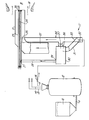
- In order that the invention may more readily be understood, the following description is given, merely by way of example, reference being made to the accompanying drawing, in which the sole Figure is a schematic side view of one embodiment of apparatus for carrying out the method of the invention.
- Referring to the drawing, the apparatus illustrated comprises a
feed coal bunker 10 from which coal with a top size of between 6 mm and 36 mm is fed via a feeder 11 to apulverizer vessel 12. Air or preferably an inert gaseous medium, such as a flue gas or steam, is fed at an elevated temperature to a plurality of nozzles (not shown) which are mounted in an annular array with the nozzles each arranged to point upwardly and at an angle between a radius and a tangent to the annulus. - The
pulverizer vessel 12 is shown with threeoutlet ducts duct 15, is shown being used according to the present invention. This duct passes via adischarge valve 16 to a burner indicated by thegeneral reference number 17. The burner comprises a combustion chamber indicated generally at 18 and having anopening 19 for the inflow of combustion air from left to right as seen in the Figure. A main nozzle 21 is mounted coaxially to the opening 19 and is fed via afeed duct 22 with particulate pulverized coal of a significantly higher diameter than the ultrafine pulverized coal flowing together with gaseous medium mixture from thepulverizer 12. - Mounted coaxially within the main nozzle 21 is an
igniter nozzle 23 having mounted coaxially therewithin an auxiliaryoil inlet pipe 24 provided with anatomizer 25 at its discharge end. Within thenozzle 23 and surrounding theatomizer 25 is aswirler 26. - The
igniter nozzle 23 is fed with light up air along its axis and with ultrafine coal via atangential connection 27 from afeedline 28 which is connected to the heavy fraction outlet 29 of acentrifugal separator 30. This separator is fed via aninlet 31 which is connected to apipe 32 which in turn is connected to theoutlet 15 of thepulverizer 12. A diverter valve 33 is positioned within thepipe 32 and can be moved from the position illustrated in which fluid flowing in is directed alonginlet 31 to theseparator 30 to a second position in which the fluid flowing in is directed along theextension 34 of the pipe to atangential inlet 35 to the main nozzle 21. - The
light fraction outlet 36 of the centrifugal separator is provided with athrottle valve 37 by means of which the light fraction can be returned to thepipe extension 34 for feeding into the main nozzle 21. - In operation of the above described apparatus, coal is fed from the
feed bunker 10 to thepulverizer 12 in which it is pulverized to an ultrafine state, that is with typically 50% by weight of the particles having a diameter of less than 12 microns. The relevant portion of the mixture of gaseous medium, that is superheated steam, or flue gas or some other inert gas, and the ultrafine coal is then passed vialine 15 to the burner. In the ignition position indicated, the mixture flows into theseparator 30 and a portion of the gaseous medium discharges viaoutlet 36 to thepipe 34 and thence is caused to flow tangentially with a swirl in the main nozzle 21. - The heavier fraction, that is a more concentrated mixture of ultrafine pulverized coal and gaseous medium flows along the
feedline 28 and is again caused to swirl in theigniter nozzle 23 with the same direction of swirl. The mixture is at an elevated temperature, preferably of the order of 130 to 150°C and in this condition is readily capable of igniting. When the temperature has risen sufficiently high within the combustion chamber, the main nozzle 21 can have the coal in a pulverized condition fed along it throughfeed pipe 22 and can be burned in a conventional way. Thereafter the supply of ultrafine pulverized coal can be cut off by closing thevalve 16. In a low load condition, it is possible to reintroduce the ultrafine coal and in this condition it is possible to have the valve 33 in the non-illustrated position so that the coal and gaseous medium mixture is fed directly to the main burner without any concentration. - In certain circumstances, it is advisable for the ignition to take place with oil initially and for this reason the
oil pipe 24 is provided and oil can be projected from that via theatomizer 25. - As indicated above, the
tangential inlet 27 to theigniter nozzle 23 produces a measure of swirl and this can be increased by theswirler 26 adjacent the outlet to the igniter nozzle. The presence of this swirl produces a central recirculating zone of hot gases and hot ultrafine coal which further enhances the flame stability. - By using ultrafine coal instead of oil, or in certain circumstances in addition to oil, a very significant saving in expense can be achieved and furthermore downstream of the furnace there is less fouling of economiser and air heater surfaces if one uses the coal rather than the oil.
- In the preferred construction illustrated, the igniter nozzle is located coaxially within the main nozzle. It is also contemplated that it could be other than coaxial and it could be coaxially outside the main nozzle.
- It is also contemplated that in the support condition, the pulverized coal in the ultrafine condition could be fed other than at an elevated temperature although this is not preferred.
Claims (7)
Applications Claiming Priority (2)
| Application Number | Priority Date | Filing Date | Title |
|---|---|---|---|
| EP84301707 | 1984-03-13 | ||
| EP84301707 | 1984-03-13 |
Publications (2)
| Publication Number | Publication Date |
|---|---|
| EP0155120A2 true EP0155120A2 (en) | 1985-09-18 |
| EP0155120A3 EP0155120A3 (en) | 1987-02-25 |
Family
ID=8192589
Family Applications (1)
| Application Number | Title | Priority Date | Filing Date |
|---|---|---|---|
| EP85301347A Withdrawn EP0155120A3 (en) | 1984-03-13 | 1985-02-27 | Method operating a coal burner |
Country Status (7)
| Country | Link |
|---|---|
| EP (1) | EP0155120A3 (en) |
| JP (1) | JPS60259817A (en) |
| KR (1) | KR850007861A (en) |
| AU (1) | AU3974985A (en) |
| DK (1) | DK111985A (en) |
| FI (1) | FI850977L (en) |
| ZA (1) | ZA851838B (en) |
Cited By (4)
| Publication number | Priority date | Publication date | Assignee | Title |
|---|---|---|---|---|
| GB2187835A (en) * | 1986-03-14 | 1987-09-16 | Laurie Edward Helyer | Pulverised fuel burner |
| EP0236339A1 (en) * | 1985-08-22 | 1987-09-16 | Weyerhaeuser Co | Energy recovery from biomass using fuel having a bimodal size distribution. |
| US4809624A (en) * | 1987-03-16 | 1989-03-07 | Shell Oil Company | Method for starting up a partial combustion process |
| WO1990003837A1 (en) * | 1988-10-14 | 1990-04-19 | Oy Finnpulva Ab | Method for binding of the sulfur compounds formed in a pulverized-coal boiler |
Families Citing this family (1)
| Publication number | Priority date | Publication date | Assignee | Title |
|---|---|---|---|---|
| JP6627310B2 (en) * | 2015-07-31 | 2020-01-08 | 中国電力株式会社 | Coal-fired power plant |
Citations (7)
| Publication number | Priority date | Publication date | Assignee | Title |
|---|---|---|---|---|
| US2494070A (en) * | 1945-09-10 | 1950-01-10 | Blaw Knox Co | Apparatus for burning pulverized fuel |
| US4147116A (en) * | 1977-09-19 | 1979-04-03 | Coal Tech Inc. | Pulverized coal burner for furnace and operating method |
| EP0017367A1 (en) * | 1979-03-16 | 1980-10-15 | MICROFUELS, Inc. | Apparatus and method for comminution of pulverulent material by fluid energy |
| US4241673A (en) * | 1979-11-05 | 1980-12-30 | Combustion Engineering, Inc. | Direct ignition of pulverized coal |
| GB2093979A (en) * | 1981-02-27 | 1982-09-08 | Steag Ag | A method for at least the two-stage ignition of a fuel dust power burner and a burner system for carrying out this method |
| US4419941A (en) * | 1982-09-02 | 1983-12-13 | Combustion Engineering, Inc. | Supplying pulverized coal to a coal-fired furnace |
| EP0102421A1 (en) * | 1982-08-27 | 1984-03-14 | JAMES HOWDEN & COMPANY LIMITED | Pulverizing apparatus |
Family Cites Families (1)
| Publication number | Priority date | Publication date | Assignee | Title |
|---|---|---|---|---|
| DE3105626C2 (en) * | 1981-02-16 | 1986-07-31 | L. & C. Steinmüller GmbH, 5270 Gummersbach | Method for providing the pilot dust for a pilot flame for igniting a pulverized coal burner flame |
-
1985
- 1985-02-27 EP EP85301347A patent/EP0155120A3/en not_active Withdrawn
- 1985-03-12 ZA ZA851838A patent/ZA851838B/en unknown
- 1985-03-12 JP JP60047620A patent/JPS60259817A/en active Pending
- 1985-03-12 DK DK111985A patent/DK111985A/en not_active Application Discontinuation
- 1985-03-12 AU AU39749/85A patent/AU3974985A/en not_active Abandoned
- 1985-03-12 FI FI850977A patent/FI850977L/en not_active Application Discontinuation
- 1985-03-12 KR KR1019850001556A patent/KR850007861A/en not_active Application Discontinuation
Patent Citations (7)
| Publication number | Priority date | Publication date | Assignee | Title |
|---|---|---|---|---|
| US2494070A (en) * | 1945-09-10 | 1950-01-10 | Blaw Knox Co | Apparatus for burning pulverized fuel |
| US4147116A (en) * | 1977-09-19 | 1979-04-03 | Coal Tech Inc. | Pulverized coal burner for furnace and operating method |
| EP0017367A1 (en) * | 1979-03-16 | 1980-10-15 | MICROFUELS, Inc. | Apparatus and method for comminution of pulverulent material by fluid energy |
| US4241673A (en) * | 1979-11-05 | 1980-12-30 | Combustion Engineering, Inc. | Direct ignition of pulverized coal |
| GB2093979A (en) * | 1981-02-27 | 1982-09-08 | Steag Ag | A method for at least the two-stage ignition of a fuel dust power burner and a burner system for carrying out this method |
| EP0102421A1 (en) * | 1982-08-27 | 1984-03-14 | JAMES HOWDEN & COMPANY LIMITED | Pulverizing apparatus |
| US4419941A (en) * | 1982-09-02 | 1983-12-13 | Combustion Engineering, Inc. | Supplying pulverized coal to a coal-fired furnace |
Non-Patent Citations (1)
| Title |
|---|
| BRENNSTOFF. W[RME. KRAFT, vol. 34, no. 3, March 1982, pages 131-135, W}rzburg, DE; K.D. RENNERT: "Kohlenstaubgefeuerter Z}ndbrenner" * |
Cited By (6)
| Publication number | Priority date | Publication date | Assignee | Title |
|---|---|---|---|---|
| EP0236339A1 (en) * | 1985-08-22 | 1987-09-16 | Weyerhaeuser Co | Energy recovery from biomass using fuel having a bimodal size distribution. |
| EP0236339A4 (en) * | 1985-08-22 | 1989-01-24 | Weyerhaeuser Co | Energy recovery from biomass using fuel having a bimodal size distribution. |
| GB2187835A (en) * | 1986-03-14 | 1987-09-16 | Laurie Edward Helyer | Pulverised fuel burner |
| GB2187835B (en) * | 1986-03-14 | 1989-12-20 | Laurie Edward Helyer | Pulverised fuel burner |
| US4809624A (en) * | 1987-03-16 | 1989-03-07 | Shell Oil Company | Method for starting up a partial combustion process |
| WO1990003837A1 (en) * | 1988-10-14 | 1990-04-19 | Oy Finnpulva Ab | Method for binding of the sulfur compounds formed in a pulverized-coal boiler |
Also Published As
| Publication number | Publication date |
|---|---|
| KR850007861A (en) | 1985-12-09 |
| DK111985A (en) | 1985-09-14 |
| AU3974985A (en) | 1985-09-19 |
| EP0155120A3 (en) | 1987-02-25 |
| ZA851838B (en) | 1985-11-27 |
| DK111985D0 (en) | 1985-03-12 |
| JPS60259817A (en) | 1985-12-21 |
| FI850977A0 (en) | 1985-03-12 |
| FI850977L (en) | 1985-09-14 |
Similar Documents
| Publication | Publication Date | Title |
|---|---|---|
| US4333405A (en) | Burner for combustion of powdered fuels | |
| KR970001468B1 (en) | Burner | |
| AU2003212026B2 (en) | Nox-reduced combustion of concentrated coal streams | |
| US7665408B2 (en) | Solid fuel burner, burning method using the same, combustion apparatus and method of operating the combustion apparatus | |
| US4924784A (en) | Firing of pulverized solvent refined coal | |
| JPH018803Y2 (en) | ||
| BG64878B1 (en) | Solid fuel burner and method for the adjustment of burning effected by the solid fuel burner | |
| EP0056709B1 (en) | Fuel burners | |
| KR900006242B1 (en) | Primary air exchange for a pulverized coal burner | |
| CN108870396A (en) | A kind of coal dust and natural gas integral type dual fuel burner | |
| JPS6159109A (en) | Burner for maintaining ignition and combustion for crushed solid fossil fuel and combustion chamber with such burner | |
| JP2003240227A (en) | Solid fuel burner and burning method thereof | |
| US5960724A (en) | Method for effecting control over a radially stratified flame core burner | |
| CA1199861A (en) | Oil and coal fired ignition burner in boiler heating assembly | |
| US5429059A (en) | Retrofitted coal-fired firetube boiler and method employed therewith | |
| EP0155120A2 (en) | Method operating a coal burner | |
| EP0165725B1 (en) | Low pressure loss burner for coal-water slurry or fuel oil | |
| US5765488A (en) | Cyclone furnace combustion system and method utilizing a coal burner | |
| US4621582A (en) | Coal burner | |
| US4614492A (en) | Burner for burning pulverulent fuel | |
| GB1585410A (en) | Burner | |
| JP2519923B2 (en) | Pulverized coal combustion equipment | |
| JP2776575B2 (en) | Pulverized coal combustion equipment | |
| SK150794A3 (en) | Torch for combustion of lignitic dust | |
| JPH05264015A (en) | Afterburner for gas turbine exhaust |
Legal Events
| Date | Code | Title | Description |
|---|---|---|---|
| PUAI | Public reference made under article 153(3) epc to a published international application that has entered the european phase |
Free format text: ORIGINAL CODE: 0009012 |
|
| AK | Designated contracting states |
Designated state(s): AT BE CH DE FR GB IT LI LU NL SE |
|
| PUAL | Search report despatched |
Free format text: ORIGINAL CODE: 0009013 |
|
| AK | Designated contracting states |
Kind code of ref document: A3 Designated state(s): AT BE CH DE FR GB IT LI LU NL SE |
|
| 17P | Request for examination filed |
Effective date: 19870813 |
|
| 17Q | First examination report despatched |
Effective date: 19880229 |
|
| STAA | Information on the status of an ep patent application or granted ep patent |
Free format text: STATUS: THE APPLICATION IS DEEMED TO BE WITHDRAWN |
|
| 18D | Application deemed to be withdrawn |
Effective date: 19900528 |
|
| RIN1 | Information on inventor provided before grant (corrected) |
Inventor name: COOPER, JAMES |