EP0154801A2 - Miniature fuse and method of fabrication therefor - Google Patents
Miniature fuse and method of fabrication therefor Download PDFInfo
- Publication number
- EP0154801A2 EP0154801A2 EP85101136A EP85101136A EP0154801A2 EP 0154801 A2 EP0154801 A2 EP 0154801A2 EP 85101136 A EP85101136 A EP 85101136A EP 85101136 A EP85101136 A EP 85101136A EP 0154801 A2 EP0154801 A2 EP 0154801A2
- Authority
- EP
- European Patent Office
- Prior art keywords
- receptacle
- conductors
- conductor
- fuse
- base
- Prior art date
- Legal status (The legal status is an assumption and is not a legal conclusion. Google has not performed a legal analysis and makes no representation as to the accuracy of the status listed.)
- Granted
Links
- 238000004519 manufacturing process Methods 0.000 title claims description 11
- 239000004020 conductor Substances 0.000 claims abstract description 76
- 229910000679 solder Inorganic materials 0.000 claims abstract description 14
- 238000005452 bending Methods 0.000 claims abstract description 8
- 238000005096 rolling process Methods 0.000 claims abstract description 7
- 238000002844 melting Methods 0.000 claims abstract description 3
- 230000008018 melting Effects 0.000 claims abstract description 3
- 239000000463 material Substances 0.000 abstract 1
- 238000005476 soldering Methods 0.000 description 6
- 230000006872 improvement Effects 0.000 description 3
- 238000012545 processing Methods 0.000 description 3
- ATJFFYVFTNAWJD-UHFFFAOYSA-N Tin Chemical compound [Sn] ATJFFYVFTNAWJD-UHFFFAOYSA-N 0.000 description 2
- 230000009471 action Effects 0.000 description 2
- 238000000926 separation method Methods 0.000 description 2
- 230000015572 biosynthetic process Effects 0.000 description 1
- 230000006735 deficit Effects 0.000 description 1
- 238000013461 design Methods 0.000 description 1
- 238000003780 insertion Methods 0.000 description 1
- 230000037431 insertion Effects 0.000 description 1
- 239000007788 liquid Substances 0.000 description 1
- 238000000034 method Methods 0.000 description 1
- 238000002360 preparation method Methods 0.000 description 1
- 230000008569 process Effects 0.000 description 1
- 230000009467 reduction Effects 0.000 description 1
- 238000007493 shaping process Methods 0.000 description 1
- 238000012549 training Methods 0.000 description 1
Images
Classifications
-
- H—ELECTRICITY
- H01—ELECTRIC ELEMENTS
- H01H—ELECTRIC SWITCHES; RELAYS; SELECTORS; EMERGENCY PROTECTIVE DEVICES
- H01H85/00—Protective devices in which the current flows through a part of fusible material and this current is interrupted by displacement of the fusible material when this current becomes excessive
- H01H85/02—Details
- H01H85/04—Fuses, i.e. expendable parts of the protective device, e.g. cartridges
- H01H85/041—Fuses, i.e. expendable parts of the protective device, e.g. cartridges characterised by the type
- H01H85/0411—Miniature fuses
- H01H85/0415—Miniature fuses cartridge type
- H01H85/0417—Miniature fuses cartridge type with parallel side contacts
Definitions
- the invention relates to a miniature fuse, consisting of a plastic base, a plastic cap and two conductors passing through the base, which are bridged within the cap by a fusible conductor soldered to the conductors, and a manufacturing method for this miniature fuse.
- the invention is suitable for all fuses in which a fusible conductor is to be fastened to it in a transverse position, and for other electrical components on which another conductor is to be securely fastened to a conductor transversely to the latter. Since the invention is to be used preferably for miniature fuses of the above type, the invention is explained in the following only with reference to miniature fuses.
- the fuse element is softly soldered in the area of the ends of the pin-shaped conductors above the base. Especially when using fusible conductors made of very thin wire, soldering is carried out by hand in order to establish a reliable connection between the conductors and the fusible conductor.
- the heat transferred can influence the soldering point between the connecting pin and the fuse element in such a way that in the worst case the soldered connection opens.
- the object of the invention is therefore to create a secure attachment of the fuse element to the conductors.
- the extremely small dimensions of the fuse element and the conductor are to be taken into account as well as the fact that fuses of the type concerned here are a typical mass-produced article, with which even a small additional effort drastically increases the manufacturing costs overall can cause.
- the invention provides that a receptacle for the fusible conductor is formed on each conductor above the base and the connection between the receptacle and the fusible conductor is strengthened by melting soft solder.
- the fuse element receives an additional fastening by means of a receptacle through which the fuse element is grasped.
- a mechanical or positive connection is thus established between the fuse element and each of the two conductors of the miniature fuse before soft solder is additionally applied to the connection point. It is sufficient if the fuse element is initially only held in or on the receptacle and is finally secured by the soft soldering.
- the possibilities for training the receptacle to perform this holding function are correspondingly diverse.
- the receptacle is preferably formed by rolling or bending the upper end of the conductor.
- the fuse element can either be retracted or hooked in, depending on whether the receptacle completely or only partially encompasses the fuse element, or the fuse element is placed on the conductor before curling or bending, so that after the receptacle has been formed, the fuse element is already in it.
- the upper end of the conductor is expediently shaped flat, namely flattened, and recesses or notches are preferably provided in the region of the receptacle.
- the conductors which are usually round in cross section, are shaped flat for fastening the fuse element, so that the receptacle encloses the fuse element with a flat section.
- the notches are very important for the quality of the soldering because the solder not only adheres to the fuse element on both sides of the receptacle, but also reaches the fuse element through the notch and creates additional bridges between the fuse element and the receptacle or the conductor.
- solder adheres to the jagged surface of the receptacle much better than if the receptacle had a smooth surface.
- this form of the receptacle also has a certain capillary action when the liquid soft solder is applied, which contributes to a further improvement in the strength of the soldered connection.
- a particularly economical method for producing the miniature fuse according to the invention consists in the fact that several bases with inserted conductors, at the upper ends of which the receptacle is prepared, are arranged in a row aligned side by side, a continuous fusible conductor thread in a stretched position and a predetermined height across the upper ends of the conductors are placed against them, the receptacle is formed by rolling or bending the upper ends of the conductors to enclose and hold the fusible conductor thread, the soft solder is applied to the receptacle and the fusible conductor in this area and the connecting pieces between the fused conductors formed be separated. Then the fastening area is reground, cleaned and cleaned if necessary, whereupon the cap is placed on the base and fastened.
- the fusible conductor thread which runs simultaneously over the entire row of conductors, is embraced and held in one step in the manufacture of the receptacle by rolling or bending the upper ends of the conductor, so that the solder can be melted in the further step, after which the so-called separation formed fuse element from the common thread, whereupon the remaining work can be carried out.
- An existing plastic, cross-sectionally circular base 1 is provided on its circumference with ribs 2 for fastening a plastic cap, not shown, and with two pin-shaped conductors 3 which pass through and are anchored in this base and whose contact pins are used, for example, to connect to printed circuit boards below the Protrude base 1.
- the conductors 3 are shaped flat and, as shown, have elongate cutouts 4. These flattened sections of the conductors 3 are rolled in, including a dash-dotted fusible conductor 6 to form a receptacle 5 comprising the fusible conductor 6, as illustrated in FIG. 2, and after prior tilting at position 7.
- the solder is then applied 8, then the separation of protruding fusible conductor parts, so that finally the final state according to FIG. 3 results.
- a device 10 which is in the form of a strip, aligned in a row next to one another. If the flattening of the conductor 6 has already taken place before the insertion of the same into the base 1, the processing in the device 10 begins with the application of a fusible conductor thread 9 in an extended position to all conductors 3. Now the conductor 3 which is attached to the Point 7 are tilted so that the fusible conductor 6 is then, as shown in Fig. 2, gripped or encompassed by the receptacle 5 formed.
- the fusible conductors 6 are separated, namely cut off from the common thread, and at the connection points may be necessary agile remaining work performed, whereupon the cap, not shown, is placed on the base 1 and firmly connected to this.
- the same size of the eyelet receptacle 5 can be used for fusible conductors of different diameters. This is because the gap between the fuse element 6 and the receptacle 5 fills the solder 8 in each case, of which as much flows into the receptacle 5 as is needed to fill the gap.
- the solder 8 is drawn into the eyelet-shaped receptacle 5.
- the receptacle 5 forms a natural protection of the soldered connection against any kind of impairment of the fastening, also against direct mechanical action, especially in the further course of production.
Landscapes
- Fuses (AREA)
- Table Devices Or Equipment (AREA)
Abstract
Description
Die Erfindung betrifft eine Kleinstsicherung, bestehend aus einem Kunststoffsockel, einer Kunststoffkappe und zwei durch den Sockel hindurchtretenden Leitern, die innerhalb der Kappe durch einen an den Leitern angelöteten Schmelzleiter überbrückt sind, sowie ein Herstellungsverfahren für diese Kleinstsicherung.The invention relates to a miniature fuse, consisting of a plastic base, a plastic cap and two conductors passing through the base, which are bridged within the cap by a fusible conductor soldered to the conductors, and a manufacturing method for this miniature fuse.
Darüber hinaus eignet sich die Erfindung für alle Schmelzsicherungen, bei denen ein Schmelzleiter in Querlage an diesem zu befestigen ist, sowie für sonstige elektrische Bauelemente, an denen an einem Leiter quer zu diesem ein anderer Leiter sicher befestigt werden soll. Da die Erfindung bevorzugt für Kleinstsicherungen der vorstehenden Art verwendet werden soll, wird die Erfindung im folgenden ausschließlich mit Bezug auf Kleinstsicherungen erläutert. Bei der Herstellung von Kleinstsicherungen wird der Schmelzleiter im Bereich der Enden der stiftförmigen Leiter oberhalb des Sockels weich aufgelötet. Insbesondere bei-Verwendung von Schmelzleitern aus sehr dünnem Draht erfolgt die Verlötung von Hand, um eine zuverlässige Verbindung zwischen den Leitern und dem Schmelzleiter herzustellen.In addition, the invention is suitable for all fuses in which a fusible conductor is to be fastened to it in a transverse position, and for other electrical components on which another conductor is to be securely fastened to a conductor transversely to the latter. Since the invention is to be used preferably for miniature fuses of the above type, the invention is explained in the following only with reference to miniature fuses. When producing miniature fuses, the fuse element is softly soldered in the area of the ends of the pin-shaped conductors above the base. Especially when using fusible conductors made of very thin wire, soldering is carried out by hand in order to establish a reliable connection between the conductors and the fusible conductor.
Aber selbst wenn dieser Lötvorgang mit größter Sorgfalt durchgeführt wird, ist die damit erreichbare Befestigung nicht allen Beanspruchungen gewachsen, denen die Kleinstsicherung im Laufe der weiteren Verarbeitung und besonders dem späteren Gebrauch ausgesetzt ist.But even if this soldering process is carried out with the greatest care, the fastening that can be achieved with it is not able to withstand all the stresses to which the miniature fuse is exposed in the course of further processing and especially later use.
Beim Einlöten der Kleinstsicherungen in Leiterplatten kann die übertragene Wärme die Lötstelle zwischen Anschlußstift und Schmelzleiter derart beeinflussen, daß im ungünstigsten Fall die Lötverbindung-aufgeht.When the miniature fuses are soldered into printed circuit boards, the heat transferred can influence the soldering point between the connecting pin and the fuse element in such a way that in the worst case the soldered connection opens.
Der Erfindung liegt daher die Aufgabe zugrunde, eine sichere Befestigung des Schmelzleiters an den Leitern zu schaffen. Bei der gewünschten Verbesserung der Befestigung sind die außerordentlich kleinen Abmessungen der Schmelzleiter und der Leiter ebenso zu berücksichtigen wie die Tatsache, daß es sich bei Sicherungen der hier betroffenen Art um einen typischen Massenartikel handelt, bei dem schon ein geringfügiger Mehraufwand eine drastische Steigerung der Fertigungskosten insgesamt verursachen kann.The object of the invention is therefore to create a secure attachment of the fuse element to the conductors. In the desired improvement of the fastening, the extremely small dimensions of the fuse element and the conductor are to be taken into account as well as the fact that fuses of the type concerned here are a typical mass-produced article, with which even a small additional effort drastically increases the manufacturing costs overall can cause.
Zur Lösung der Aufgabe ist erfindungsgemäß vorgesehen, daß an jedem Leiter oberhalb des Sockels eine Aufnahme für den Schmelzleiter gebildet und die Verbindung zwischen der Aufnahme und dem Schmelzleiter durch Aufschmelzen von Weichlot gefestigt ist.To achieve the object, the invention provides that a receptacle for the fusible conductor is formed on each conductor above the base and the connection between the receptacle and the fusible conductor is strengthened by melting soft solder.
Nach dieser Lösung erhält der Schmelzleiter neben der Lötung eine zusätzliche Befestigung durch eine Aufnahme, durch die der Schmelzleiter erfaßt wird. Es wird also eine mechanische bzw. formschlüssige Verbindung zwischen dem Schmelzleiter und jedem der beiden Leiter der Kleinstsicherung hergestellt, ehe zusätzlich Weichlot auf die Verbindungsstelle aufgebracht wird. Dabei reicht es aus, wenn der Schmelzleiter in oder an der Aufnahme zunächst nur gehalten wird und seine endgültige Befestigung durch die Weichlötung erhält. Entsprechend vielseitig sind die Möglichkeiten für die Ausbildung der Aufnahme zur Ausführung dieser Haltefunktion.According to this solution, in addition to the soldering, the fuse element receives an additional fastening by means of a receptacle through which the fuse element is grasped. A mechanical or positive connection is thus established between the fuse element and each of the two conductors of the miniature fuse before soft solder is additionally applied to the connection point. It is sufficient if the fuse element is initially only held in or on the receptacle and is finally secured by the soft soldering. The possibilities for training the receptacle to perform this holding function are correspondingly diverse.
Vorzugsweise ist die Aufnahme jedoch durch Einrollen oder Umbiegen des oberen Endes des Leiters gebildet. In diese nach Art einer Öse geformte Aufnahme läßt sich der Schmelzleiter entweder nachträglich einziehen oder einhängen, je nachdem, ob die Aufnahme den Schmelzleiter ganz oder nur teilweise umfaßt, oder man legt den Schmelzleiter bereits vor dem Einrollen oder Umbiegen auf den Leiter, so daß sich nach der Ausformung der Aufnahme der Schmelzleiter bereits in dieser befindet.However, the receptacle is preferably formed by rolling or bending the upper end of the conductor. In this receptacle shaped like an eyelet, the fuse element can either be retracted or hooked in, depending on whether the receptacle completely or only partially encompasses the fuse element, or the fuse element is placed on the conductor before curling or bending, so that after the receptacle has been formed, the fuse element is already in it.
Das obere Ende des Leiters ist zweckmäßig flach geformt, nämlich abgeflacht, und im Bereich der Aufnahme sind vorzugsweise Ausnehmungen oder Ausklinkungen vorgesehen. Die im Querschnitt gewöhnlich runden Leiter werden für die Befestigung des Schmelzleiters flach geformt, so daß die Aufnahme den Schmelzleiter mit einem flächenhaften Abschnitt umschließt. Die Ausklinkungen sind für Qualität der Lötung sehr wesentlich, weil das Lötzinn so an dem Schmelzleiter nicht nur beiderseits der Aufnahme haftet, sondern den Schmelzleiter auch durch die Ausklinkung hindurch erreicht und zusätzliche Brücken zwischen dem Schmelzleiter und der Aufnahme bzw. dem Leiter schafft. Darüber hinaus haftet das Lötzinn an der in dieser Weise zerklüfteten Oberfläche der Aufnahme wesentlich besser als im Falle einer glattflächigen Ausbildung der Aufnahme. Schließlich geht von dieser Form der Aufnahme auch eine gewisse Kapillarwirkung beim Aufbringen des flüssigen Weichlots aus, was zu einer weiteren Verbesserung der Festigkeit der Lötverbindung beiträgt.The upper end of the conductor is expediently shaped flat, namely flattened, and recesses or notches are preferably provided in the region of the receptacle. The conductors, which are usually round in cross section, are shaped flat for fastening the fuse element, so that the receptacle encloses the fuse element with a flat section. The notches are very important for the quality of the soldering because the solder not only adheres to the fuse element on both sides of the receptacle, but also reaches the fuse element through the notch and creates additional bridges between the fuse element and the receptacle or the conductor. In addition, the solder adheres to the jagged surface of the receptacle much better than if the receptacle had a smooth surface. Finally, this form of the receptacle also has a certain capillary action when the liquid soft solder is applied, which contributes to a further improvement in the strength of the soldered connection.
Es hat sich gezeigt, daß an dem oberen flach geformten Ende des Leiters die Ausbildung eines länglichen Ausschnitts zur Erzielung der vorgenannten Wirkungen am vorteilhaftesten ist.It has been found that the formation of an elongated cutout at the upper flat-shaped end of the conductor is most advantageous for achieving the aforementioned effects.
Ein besonders wirtschaftliches Verfahren zur Herstellung der erfindungsgemäßen Kleinstsicherung besteht nach der Erfindung darin, daß mehrere Sockel mit eingesetzten Leitern, an deren oberen Enden die Aufnahme vorbereitet ist, in einer Reihe ausgerichtet nebeneinander angeordnet werden, ein durchgehender Schmelzleiterfaden in gestreckter Lage und vorgegebener Höhe quer über die oberen Enden der Leiter an diese angelegt wird, die Aufnahme durch Einrollen oder Umbiegen der oberen Enden der Leiter zum Umfassen und Halten des Schmelzleiterfadens gebildet wird, das Weichlot auf die Aufnahme und den Schmelzleiter in diesem Bereich aufgebracht wird und die Verbindungsstücke zwischen den gebildeten Schmelzleitern abgetrennt werden. Danach wird der Befestigungsbereich gegebenenfalls nachgeschliffen, geputzt und gesäubert, worauf die Kappe auf den Sockel aufgesetzt und befestigt wird.A particularly economical method for producing the miniature fuse according to the invention consists in the fact that several bases with inserted conductors, at the upper ends of which the receptacle is prepared, are arranged in a row aligned side by side, a continuous fusible conductor thread in a stretched position and a predetermined height across the upper ends of the conductors are placed against them, the receptacle is formed by rolling or bending the upper ends of the conductors to enclose and hold the fusible conductor thread, the soft solder is applied to the receptacle and the fusible conductor in this area and the connecting pieces between the fused conductors formed be separated. Then the fastening area is reground, cleaned and cleaned if necessary, whereupon the cap is placed on the base and fastened.
Die Vorbereitung der Ausformung der Aufnahme am oberen Ende jedes Leiters besteht, je nach der gewünschten Form der Aufnahme, beispielsweise im Ankippen, nämlich in einem geringfügigen Umbiegen des Endes des Leiters, wenn die Aufnahme durch Einrollen hergestellt werden soll. Auch die Flachformung und die Herstellung eines länglichen Ausschnitts in dem Leiter oberhalb des Sockels zählt zu den vorbereitenden Arbeiten, bevor der Schmelzleiterfaden befestigt wird. Wesentlich ist, daß eine Vielzahl von Einheiten aus Sockeln mit eingesetzten Leitern gleichzeitig bearbeitet wird, indem die Sockel in einer Vorrichtung in einer Reihe ausgerichtet nebeneinander angeordnet werden. Der gleichzeitig über die gesamte Reihe der Leiter verlaufende Schmelzleiterfaden wird in einem Arbeitsgang beim Herstellen der Aufnahme durch Einrollen oder Umbiegen der oberen Enden der Leiter von diesem umfaßt und gehalten, so daß im weiteren Arbeitsgang das Aufschmelzen des Lötzinns erfolgen kann, danach das Abtrennen der so gebildeten Schmelzleiter von dem gemeinsamen Faden, worauf die Restarbeiten ausgeführt werden können.The preparation of the shape of the receptacle at the upper end of each conductor, depending on the desired shape of the receptacle, for example in tilting, namely in a slight bending of the end of the conductor if the receptacle is to be produced by curling. Also the flat shaping and the production of an elongated Aus Cutting in the conductor above the base is one of the preparatory work before the fuse element thread is attached. It is essential that a multiplicity of units consisting of bases with inserted conductors are processed at the same time by arranging the bases aligned in a row next to one another. The fusible conductor thread, which runs simultaneously over the entire row of conductors, is embraced and held in one step in the manufacture of the receptacle by rolling or bending the upper ends of the conductor, so that the solder can be melted in the further step, after which the so-called separation formed fuse element from the common thread, whereupon the remaining work can be carried out.
Insgesamt wird so ohne erheblichen Mehraufwand eine wesentliche Verbesserung der Qualität der Befestigung des Schmelzleiters an den Leitern der Kleinstsicherung erreicht. Durch eine erhebliche Reduzierung des Ausschußanteils können sich vielmehr Einsparungen ergeben. Sehr wesentlich sind die Vorteile, die sich aufgrund der erfindungsgemäßen Ausbildung und der höheren Zuverlässigkeit der Verbindung zwischen Schmelzleiter und Leiter bei der Verwendung der Kleinstsicherung ergeben.All in all, a significant improvement in the quality of the attachment of the fuse element to the conductors of the miniature fuse is achieved without considerable additional effort. A considerable reduction in the number of rejects can result in savings. The advantages that result from the design according to the invention and the higher reliability of the connection between the fuse element and the conductor when using the miniature fuse are very important.
Die Erfindung wird nachfolgend mit Bezug auf die Zeichnung näher erläutert. In den Zeichnungen zeigen:
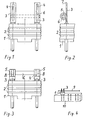
- Fig. 1 eine Vorderansicht eines Sockels einer Kleinstsicherung im Fertigungszustand vor dem Einrollen von durch den Sockel hindurchtretenden Leitern;
- Fig. 2 eine Seitensansicht zu Fig. 1 mit Darstellung des nächsten Fertigungsschritts;
- Fig. 3 eine Vorderansicht des Sockels nach erfolgter Befestigung eines Schmelzleiters an den Leitern;
- Fig. 4 eine schematische Darstellung einer bei der Herstellung der Kleinstsicherung benutzten Vorrichtung.
- Figure 1 is a front view of a base of a miniature fuse in the manufacturing state before rolling in of conductors passing through the base.
- FIG. 2 shows a side view of FIG. 1, showing the next manufacturing step;
- 3 shows a front view of the base after a fuse element has been attached to the conductors;
- Fig. 4 is a schematic representation of a device used in the manufacture of the miniature fuse.
Ein aus Kunststoff bestehender, im Querschnitt kreisförmiger Sockel 1 ist an seinem Umfang mit Rippen 2 für die Befestigung einer nicht dargestellten Kunststoffkappe sowie mit zwei durch diesen Sockel hindurchtretenden und in diesem verankerten stiftförmigen Leitern 3 versehen, deren zum Anschluß beispielsweise an Leiterplatten dienende Kontaktstifte unterhalb des Sockels 1 vorstehen. Oberhalb des Sockels 1 sind die Leiter 3 flach geformt und weisen, wie dargestellt, längliche Ausschnitte 4 auf. Diese abgeflachten Abschnitte der Leiter 3 werden unter Einbeziehung eines strich-punktierten Schmelzleiters 6 unter Bildung einer den Schmelzleiter 6 umfassenden Aufnahme 5, wie in Fig. 2 veranschaulicht, eingerollt, und zwar nach vorherigem Ankippen an der Stelle 7. Danach erfolgt das Aufbringen des Lötzinns 8, darauf das Abtrennen überstehender Schmelzleiterteile, so daß sich schließlich der Endzustand nach Fig. 3 ergibt.An existing plastic, cross-sectionally
Für eine gemeinsame Bearbeitung einer Vielzahl von Einheiten, bestehend aus Sockel 1 und Leitern 3, werden diese Einheiten, wie schematisch in Fig. 4 dargestellt wird, in eine Vorrichtung 10 , die die Form einer Leiste hat, in einer Reihe nebeneinander ausgerichtet eingesetzt. Falls die Abflachung der Leiter 6 bereits vor dem Einsetzen derselben in die Sockel 1 erfolgt ist, beginnt die Bearbeitung in der Vorrichtung 10 mit dem Anlegen eines Schmelzleiterfadens 9 in gestreckter Lage an sämtliche Leiter 3. Nun wird das Einrollen der Leiter 3, die an der Stelle 7 angekippt sind, so durchgeführt, daß der Schmelzleiter 6 anschließend, wie in Fig. 2 dargestellt, von der gebildeten Aufnahme 5 erfaßt bzw. umfaßt ist. Nach dem Aufbringen des aus Zinn bestehenden Weichlots auf den gesamten Verbindungsbereich zwischen Aufnahme 5 und Schmelzleiter 6 werden die Schmelzleiter 6 vereinzelt, nämlich von dem gemeinsamen Faden abgeschnitten, und an den Verbindungsstellen werden gegebenenfalls notwendige Restarbeiten ausgeführt, worauf die nicht dargestellte Kappe auf den Sockel 1 aufgesetzt und mit diesem fest verbunden wird.For a joint processing of a multiplicity of units, consisting of
Abschließend sei zur Veranschaulichung der geringen Baugröße der Kleinstsicherung auf deren ungefähre Abmessungen hingewiesen:
- Sockeldurchmesser ca. 7 mm
- Leiterdurchmesser ca. 0,6 mm
- Breite der abgeflachten Leiter ca. 1,2 mm
- Base diameter approx. 7 mm
- Conductor diameter approx. 0.6 mm
- Width of the flattened conductor approx. 1.2 mm
Leiterlänge oberhalb des Sockels vor dem Einrollen ca. 4,5 mm Innendurchmesser der Aufnahme ca. 1 mm.Conductor length above the base before rolling in approx. 4.5 mm inner diameter of the receptacle approx. 1 mm.
Es versteht sich von selbst, daß sich vorstehende Abmessungen lediglich auf ein einziges Ausführungsbeispiel_ beziehen und die Erfindung hierauf keinesfalls beschränkt werden soll.It goes without saying that the above dimensions relate only to a single exemplary embodiment and the invention should in no way be limited to these.
Es noch darauf hingewiesen, daß die gleiche Größe der ösenförmigen Aufnahme 5 für Schmelzleiter verschiedener Durchmesser verwendet werden kann. Denn den Zwischenraum zwischen dem Schmelzleiter 6 und der Aufnahme 5 füllt in jedem Falle das Lötzinn 8 aus, von dem jeweils so viel in die Aufnahme 5 fließt, wie gebraucht wird, um den Zwischenraum auszufüllen. Bei der Befestigung sehr dünner Schmelzleiter 6 ergibt sich sogar durch den größeren Zwischenraum zwischen diesem und der Aufnahme 5 eine noch größere Kapillarwirkung, d.h. das Lötzinn 8 wird in die ösenförmige Aufnahme 5 gezogen. Die Aufnahme 5 bildet einen natürlichen Schutz der Lötverbindung gegen jegliche Art der Beeinträchtigung der Befestigung, auch gegenüber direkter mechanischer Einwirkung, vor allem auch im weiteren Fertigungsverlauf.It should also be noted that the same size of the
Claims (5)
Priority Applications (1)
| Application Number | Priority Date | Filing Date | Title |
|---|---|---|---|
| AT85101136T ATE42866T1 (en) | 1984-03-10 | 1985-02-04 | MINIATURE FUSE AND METHOD OF MANUFACTURE THEREOF. |
Applications Claiming Priority (2)
| Application Number | Priority Date | Filing Date | Title |
|---|---|---|---|
| DE3408854 | 1984-03-10 | ||
| DE19843408854 DE3408854A1 (en) | 1984-03-10 | 1984-03-10 | LOW FUSE AND MANUFACTURING METHOD HERE |
Publications (3)
| Publication Number | Publication Date |
|---|---|
| EP0154801A2 true EP0154801A2 (en) | 1985-09-18 |
| EP0154801A3 EP0154801A3 (en) | 1986-04-02 |
| EP0154801B1 EP0154801B1 (en) | 1989-05-03 |
Family
ID=6230133
Family Applications (1)
| Application Number | Title | Priority Date | Filing Date |
|---|---|---|---|
| EP85101136A Expired EP0154801B1 (en) | 1984-03-10 | 1985-02-04 | Miniature fuse and method of fabrication therefor |
Country Status (5)
| Country | Link |
|---|---|
| US (1) | US4628293A (en) |
| EP (1) | EP0154801B1 (en) |
| JP (1) | JPS60258824A (en) |
| AT (1) | ATE42866T1 (en) |
| DE (2) | DE3408854A1 (en) |
Cited By (2)
| Publication number | Priority date | Publication date | Assignee | Title |
|---|---|---|---|---|
| GB2204457A (en) * | 1987-05-05 | 1988-11-09 | Dubilier Plc | Sub-miniature fuse |
| EP0484703A2 (en) * | 1990-11-05 | 1992-05-13 | Wickmann-Werke GmbH | Electrical fuse |
Families Citing this family (10)
| Publication number | Priority date | Publication date | Assignee | Title |
|---|---|---|---|---|
| JPH0720828Y2 (en) * | 1989-06-14 | 1995-05-15 | エス・オー・シー株式会社 | Ultra-small current fuse |
| US5287079A (en) * | 1992-11-09 | 1994-02-15 | Cooper Industries, Inc. | Sub-miniature plastic fuse |
| DE19803605B4 (en) * | 1998-01-30 | 2004-08-26 | Wickmann-Werke Gmbh | Process for manufacturing electrical fuses |
| US6462472B1 (en) * | 2000-04-12 | 2002-10-08 | Chen Hsien Huang | Fixing structure for safety fuse of Christmas lamp |
| US20100060406A1 (en) * | 2006-06-16 | 2010-03-11 | Smart Electronics Inc. | Small-sized surface-mounted fuse and method of manufacturing the same |
| US20080143471A1 (en) * | 2006-12-15 | 2008-06-19 | Chun-Chang Yen | Fuse assembly |
| US20090108980A1 (en) * | 2007-10-09 | 2009-04-30 | Littelfuse, Inc. | Fuse providing overcurrent and thermal protection |
| US8576041B2 (en) * | 2008-12-17 | 2013-11-05 | Cooper Technologies Company | Radial fuse base and assembly |
| KR101038401B1 (en) * | 2009-04-21 | 2011-06-03 | 스마트전자 주식회사 | A small fuse and the manufacturing method of it |
| DE102009019059A1 (en) * | 2009-04-27 | 2010-11-04 | Chun-Chang Yen | Base for fuse, has wire which is inserted for connection pin in vending machine, where connection pin is cut into sections and bulge is attached to connection pin |
Citations (4)
| Publication number | Priority date | Publication date | Assignee | Title |
|---|---|---|---|---|
| FR762124A (en) * | 1932-11-15 | 1934-04-04 | Molded insulating material circuit breaker bar with partition to prevent the propagation of the electric arc | |
| FR948836A (en) * | 1947-06-19 | 1949-08-11 | Fuse holder manufacturing process | |
| DE3033529A1 (en) * | 1979-09-08 | 1981-04-02 | San-O Industrial Co., Ltd., Tokyo | MINIATURE MELTFUSE |
| DE8411568U1 (en) * | 1984-04-13 | 1984-08-23 | Wickmann-Werke GmbH, 5810 Witten | Miniature fuse |
Family Cites Families (7)
| Publication number | Priority date | Publication date | Assignee | Title |
|---|---|---|---|---|
| US3123696A (en) * | 1964-03-03 | Cffalq l | ||
| US1008411A (en) * | 1908-11-09 | 1911-11-14 | Henry A Hills | Safety device for electrically-heated implements. |
| US3253244A (en) * | 1963-11-06 | 1966-05-24 | Indak Mfg Corp | Electrical resistors |
| WO1981001627A1 (en) * | 1979-12-03 | 1981-06-11 | Beswick Kenneth E Ltd | Method of manufacturing plug-in electrical fuses and a fuse produced by the method |
| JPS56112856U (en) * | 1980-01-31 | 1981-08-31 | ||
| JPS58184219A (en) * | 1982-04-21 | 1983-10-27 | 日本電気ホームエレクトロニクス株式会社 | Method of producing temperature fuse |
| US4483064A (en) * | 1982-07-22 | 1984-11-20 | Bel Fuse, Inc. | Process of multiple fuse construction |
-
1984
- 1984-03-10 DE DE19843408854 patent/DE3408854A1/en not_active Withdrawn
-
1985
- 1985-02-04 DE DE8585101136T patent/DE3570011D1/en not_active Expired
- 1985-02-04 EP EP85101136A patent/EP0154801B1/en not_active Expired
- 1985-02-04 AT AT85101136T patent/ATE42866T1/en not_active IP Right Cessation
- 1985-03-05 US US06/708,532 patent/US4628293A/en not_active Expired - Lifetime
- 1985-03-11 JP JP60048091A patent/JPS60258824A/en active Granted
Patent Citations (4)
| Publication number | Priority date | Publication date | Assignee | Title |
|---|---|---|---|---|
| FR762124A (en) * | 1932-11-15 | 1934-04-04 | Molded insulating material circuit breaker bar with partition to prevent the propagation of the electric arc | |
| FR948836A (en) * | 1947-06-19 | 1949-08-11 | Fuse holder manufacturing process | |
| DE3033529A1 (en) * | 1979-09-08 | 1981-04-02 | San-O Industrial Co., Ltd., Tokyo | MINIATURE MELTFUSE |
| DE8411568U1 (en) * | 1984-04-13 | 1984-08-23 | Wickmann-Werke GmbH, 5810 Witten | Miniature fuse |
Cited By (3)
| Publication number | Priority date | Publication date | Assignee | Title |
|---|---|---|---|---|
| GB2204457A (en) * | 1987-05-05 | 1988-11-09 | Dubilier Plc | Sub-miniature fuse |
| EP0484703A2 (en) * | 1990-11-05 | 1992-05-13 | Wickmann-Werke GmbH | Electrical fuse |
| EP0484703A3 (en) * | 1990-11-05 | 1993-03-24 | Wickmann-Werke Gmbh | Electrical fuse |
Also Published As
| Publication number | Publication date |
|---|---|
| EP0154801A3 (en) | 1986-04-02 |
| US4628293A (en) | 1986-12-09 |
| JPH0542767B2 (en) | 1993-06-29 |
| ATE42866T1 (en) | 1989-05-15 |
| JPS60258824A (en) | 1985-12-20 |
| DE3570011D1 (en) | 1989-06-08 |
| DE3408854A1 (en) | 1985-09-12 |
| EP0154801B1 (en) | 1989-05-03 |
Similar Documents
| Publication | Publication Date | Title |
|---|---|---|
| DE3808971A1 (en) | COMPOSED COMPONENT | |
| EP0154801B1 (en) | Miniature fuse and method of fabrication therefor | |
| DE2234961B2 (en) | Process for the production of connectors for circuit boards | |
| DE68913843T2 (en) | Electrical connector with a solder. | |
| DE2444892C3 (en) | Process for the production of strip-shaped connection elements | |
| DE1293268B (en) | Circuit module | |
| DE3010876A1 (en) | METHOD FOR PRODUCING A CIRCUIT BOARD | |
| DE3134381A1 (en) | METHOD FOR PRODUCING SOCKET BASES FOR LIGHT-EMITTING DIODE DISPLAY ELEMENTS | |
| DE69109368T2 (en) | Fuse unit, in particular for printed circuits. | |
| DE3304263A1 (en) | Glass melting fuses and a method for their production | |
| DE2603151C3 (en) | Component for switching and / or isolating strips in distributors for telecommunications systems | |
| DE19636237A1 (en) | Low-voltage circuit-breaker switching contact system | |
| EP0471922A2 (en) | Fuse element | |
| DE1916554B2 (en) | Method for manufacturing semiconductor rectifier arrangements | |
| DE3724033C2 (en) | ||
| DE2509763C3 (en) | Multi-wire oxygen electrode and method of making the same - US Pat | |
| DE3150125A1 (en) | METHOD FOR PRODUCING A RELAY AND RELATED PRODUCED RELAY | |
| DE1963313B2 (en) | Solderless terminal tag for bared wires - has spring fingers at one end with gripping hollows to hold two orthogonal wires | |
| DE3715093A1 (en) | METHOD FOR CONNECTING A COIL | |
| DE2820002A1 (en) | Terminal for circuit board - has connecting wires pushed in holes in board with grooves and collars at their tops | |
| DE602004001871T2 (en) | Contact socket with solder paste and manufacturing process | |
| DE19803605B4 (en) | Process for manufacturing electrical fuses | |
| AT401125B (en) | METHOD FOR PRODUCING A THERMAL FUSE | |
| DE19851532A1 (en) | Fuseholder for mounting on PCB, includes injection-molded base for dimensional stability and strength assisting automatic mounting and soldering, with holders and mounting pins projecting on each side | |
| DE3913842A1 (en) | Electrical cable converter - has cutting elements formed to penetrate insulation during assembly |
Legal Events
| Date | Code | Title | Description |
|---|---|---|---|
| PUAI | Public reference made under article 153(3) epc to a published international application that has entered the european phase |
Free format text: ORIGINAL CODE: 0009012 |
|
| AK | Designated contracting states |
Designated state(s): AT BE CH DE FR GB IT LI LU NL SE |
|
| PUAL | Search report despatched |
Free format text: ORIGINAL CODE: 0009013 |
|
| AK | Designated contracting states |
Kind code of ref document: A3 Designated state(s): AT BE CH DE FR GB IT LI LU NL SE |
|
| 17P | Request for examination filed |
Effective date: 19860515 |
|
| 17Q | First examination report despatched |
Effective date: 19871027 |
|
| ITF | It: translation for a ep patent filed | ||
| GRAA | (expected) grant |
Free format text: ORIGINAL CODE: 0009210 |
|
| AK | Designated contracting states |
Kind code of ref document: B1 Designated state(s): AT BE CH DE FR GB IT LI LU NL SE |
|
| PG25 | Lapsed in a contracting state [announced via postgrant information from national office to epo] |
Ref country code: SE Effective date: 19890503 Ref country code: BE Effective date: 19890503 |
|
| REF | Corresponds to: |
Ref document number: 42866 Country of ref document: AT Date of ref document: 19890515 Kind code of ref document: T |
|
| REF | Corresponds to: |
Ref document number: 3570011 Country of ref document: DE Date of ref document: 19890608 |
|
| ET | Fr: translation filed | ||
| GBT | Gb: translation of ep patent filed (gb section 77(6)(a)/1977) | ||
| PG25 | Lapsed in a contracting state [announced via postgrant information from national office to epo] |
Ref country code: AT Effective date: 19900204 |
|
| PG25 | Lapsed in a contracting state [announced via postgrant information from national office to epo] |
Ref country code: LU Free format text: LAPSE BECAUSE OF NON-PAYMENT OF DUE FEES Effective date: 19900228 Ref country code: LI Effective date: 19900228 Ref country code: CH Effective date: 19900228 |
|
| PLBE | No opposition filed within time limit |
Free format text: ORIGINAL CODE: 0009261 |
|
| STAA | Information on the status of an ep patent application or granted ep patent |
Free format text: STATUS: NO OPPOSITION FILED WITHIN TIME LIMIT |
|
| 26N | No opposition filed | ||
| REG | Reference to a national code |
Ref country code: CH Ref legal event code: PL |
|
| ITTA | It: last paid annual fee | ||
| REG | Reference to a national code |
Ref country code: GB Ref legal event code: IF02 |
|
| PGFP | Annual fee paid to national office [announced via postgrant information from national office to epo] |
Ref country code: DE Payment date: 20030129 Year of fee payment: 19 |
|
| PGFP | Annual fee paid to national office [announced via postgrant information from national office to epo] |
Ref country code: GB Payment date: 20030130 Year of fee payment: 19 |
|
| PGFP | Annual fee paid to national office [announced via postgrant information from national office to epo] |
Ref country code: NL Payment date: 20030204 Year of fee payment: 19 |
|
| PGFP | Annual fee paid to national office [announced via postgrant information from national office to epo] |
Ref country code: FR Payment date: 20030206 Year of fee payment: 19 |
|
| PG25 | Lapsed in a contracting state [announced via postgrant information from national office to epo] |
Ref country code: GB Free format text: LAPSE BECAUSE OF NON-PAYMENT OF DUE FEES Effective date: 20040204 |
|
| PG25 | Lapsed in a contracting state [announced via postgrant information from national office to epo] |
Ref country code: NL Free format text: LAPSE BECAUSE OF NON-PAYMENT OF DUE FEES Effective date: 20040901 Ref country code: DE Free format text: LAPSE BECAUSE OF NON-PAYMENT OF DUE FEES Effective date: 20040901 |
|
| GBPC | Gb: european patent ceased through non-payment of renewal fee |
Effective date: 20040204 |
|
| PG25 | Lapsed in a contracting state [announced via postgrant information from national office to epo] |
Ref country code: FR Free format text: LAPSE BECAUSE OF NON-PAYMENT OF DUE FEES Effective date: 20041029 |
|
| NLV4 | Nl: lapsed or anulled due to non-payment of the annual fee |
Effective date: 20040901 |
|
| REG | Reference to a national code |
Ref country code: FR Ref legal event code: ST |