EP0154745A2 - Offshore waste disposal - Google Patents
Offshore waste disposal Download PDFInfo
- Publication number
- EP0154745A2 EP0154745A2 EP84308337A EP84308337A EP0154745A2 EP 0154745 A2 EP0154745 A2 EP 0154745A2 EP 84308337 A EP84308337 A EP 84308337A EP 84308337 A EP84308337 A EP 84308337A EP 0154745 A2 EP0154745 A2 EP 0154745A2
- Authority
- EP
- European Patent Office
- Prior art keywords
- units
- hole
- platform
- waste material
- drilling
- Prior art date
- Legal status (The legal status is an assumption and is not a legal conclusion. Google has not performed a legal analysis and makes no representation as to the accuracy of the status listed.)
- Withdrawn
Links
Images


Classifications
-
- G—PHYSICS
- G21—NUCLEAR PHYSICS; NUCLEAR ENGINEERING
- G21F—PROTECTION AGAINST X-RADIATION, GAMMA RADIATION, CORPUSCULAR RADIATION OR PARTICLE BOMBARDMENT; TREATING RADIOACTIVELY CONTAMINATED MATERIAL; DECONTAMINATION ARRANGEMENTS THEREFOR
- G21F9/00—Treating radioactively contaminated material; Decontamination arrangements therefor
- G21F9/28—Treating solids
- G21F9/34—Disposal of solid waste
- G21F9/36—Disposal of solid waste by packaging; by baling
Definitions
- the present invention relates to the offshore disposal of waste materials, especially noxious waste materials such as toxic or nuclear wastes.
- waste materials especially noxious waste materials such as toxic or nuclear wastes.
- the dumping of waste into the sea, for example from a ship, is not generally acceptable to the public as a method of waste disposal.
- the present invention provides a method of disposing of waste materials which comprises
- the method preferably comprises
- the present invention also provides apparatus for use in the latter method, comprising
- a method according to the invention is particularly suitable for offshore waters up to 150 m in depth using a jack-up drilling platform.
- the disposal bore hole should be at least 1000 m in depth below the seabed (e.g. about 1500 m).
- the diameter of the bore should be at least 50 cm (e.g. about 60 cm to 1 m) and most preferably the bore should be cased over at least a majority of its length to prevent internal obstruction, or collapse.
- Geographical areas particularly suitable for application of a method of waste disposal according to the invention are those where no hydrocarbon resources are present at any depth, and most especially those areas having several impermeable subterranean layers without faults.
- the units of waste material are suitably of comparable diameter to the standard drill sizes used in offshore drilling procedures e.g. they could be cylindrical in shape and from about 25 cm to about 1 m in diameter and about 1m to 5m in lenoth.
- Individual units may be lowered into a hole at the end of a wire or cable, or may be allowed to slide down a hole under the influence of their own weight and impeded by the hydrodynamic resistance of fluid displaced from the hole.
- a plurality of units may be lowered into a bore hole together in a string.
- the units are in the form of canisters or sealed pipe lengths filled with waste material. It is preferred that the waste materials be sealed into suitable canisters or pipe lengths before transport to the disposal site.
- Storage of the units on the platform may be at deck level or may be below deck. Access to a below deck storage bay may suitably be through the deck floor from above; such a bay may be provided with a sliding cover.
- units be transported to and/or from the platform in groups (e.g. 4, 6, 8 or 9) in compartmentalised containers each having a protective cell for each unit.
- groups e.g. 4, 6, 8 or 9
- the waste material is radioactive it is preferable that any, most preferably each, of the units, containers and storage facilities are shielded to prevent radiation leakage.
- Each container for a group of units may be of a size suitable for transport by conventional road or rail haulage.
- Units of waste material may be transferred from storage to a bore hole by any mechanical means e.g. conveyor, crane, robotic arm, etc.
- radioactive waste is sealed in pipe lengths e.g. steel drill piping, and the thus formed cylinders (2) are loaded into individual protective cells in a shielded container (3) sealed by a removable lid (7).
- a plurality of such containers (3) are then taken by rail (4) to a convenient port (5) where they are loaded onto a ship (6).
- the containers (3) are removed from the ship (6), e.g. by use of a crane (11) mounted on the platform deck (12), and placed in a storage bay (13) set into the platform deck.
- the bay (13) is radiation shielded and has a protective sliding cover (14).
- the platform carries a drilling derrick (15) extending over the side of the deck. Drilling operations may be carried out whilst containers are being off-loaded from the supply ship.
- the drilling derrick (15) may be either moveable on tracks or may be constructed so as to allow passage of a gantry crane (20) beneath it in order to allow access to the head of the bore hole (16).
- a gantry crane runs between the storage bay and the bore hole on tracks or skids (21) laid on the deck.
- the gantry crane (20) is provided with a shielded receptacle (22) for carrying the cylinders (2).
- the cover (14) of the storage bay (13) is removed, the receptacle (22) is placed over a cell in a container (3) and a cylinder (2) is drawn up into the receptacle (22).
- the cover (14) of the storage bay is replaced and the gantry crane (20) is moved to the head of the bore hole (16) where the cylinder (2) is released from the receptacle (22).
- the procedure is repeated to fill the bore hole with cylinders to a predetermined level.
- the top of the bore hole is then sealed (30), for example with concrete grouting, to contain the waste materials below the seabed.
- Emptied containers (31) may be off-loaded from the platform to the supply vessel whilst cylinder disposal is in progress.
- waste material (40) e.g. radioactive waste
- the line may, for example, be made of steel or aromatic polyamide resin - e.g. "Kevlar” (Registered Trade Mark).
- canisters (2) may be lowered into more than one hole simultaneously.
- Offshore bore-holes may be drilled from bottom supported marine drilling platforms using a drill string formed by interconnection of individual standard length drill sections and having a drilling tool attached at the end; as the drill string is extended section by section the bore is drilled deeper.
- canisters of waste material may be attached as an extension at the end of a drill string, in place of the drilling tool, for lowering into a pre-drilled bore.
- a number of canisters may be interconnected to form a single unit of similar dimensions to a standard length drill section and attached to the string or, alternatively, a number of canisters of suitable diameter may be loaded into a tube having similar dimensions to a standard length drill section and attached to the string.
- noxious waste (40) is presealed in - a protective canister (2).
- a number of such canisters (2) are loaded into a casing(50) having suitably sized apertures (51).
- a mechanical catch (52) is provided if required to hold each canister (2) in place.
- each casing(50) acts as a magazine for loading with a number of canisters (2).
- the casing (50) is of comparable dimensions to a drill section and may have a suitable means (54) for attachment to a standard drill string or cable. In this case the canisters (2) have no structural load imposed on them as they are lowered down a disposal hole (16).
- noxious waste (40) is presealed in a protective canister (2) having complementary threaded connector means (58) at each end of the outer shell. A plurality of such canisters (2) may then be interconnected to provide sections of suitable length for attachment to a drill string. Where the waste material (40) is liable to generate heat (e.g. where the material (40) is high grade nuclear waste) spacer-sections (59) may be incorporated to aid heat disipation.
- the canisters (2), and spacers (59) have a structural load imposed upon them as they are lowered down a disposal hole (16) and so they are reinforced to withstand both this load and the_torquing of the joints.
- the complete lengths for attachment to the drill string may be prepared either on shore or offshore on the platform as is most convenient.
- a number of such lengths are lowered into a disposal hole (16) at the end of a drill string and a conventional oil well tool is used to disconnect the sections containing waste canisters (2) and the drill string is withdrawn.
- a bottom-supported drilling platform is essential for the method of the invention since it provides a safe and stable base for storage and drilling.
- a jack-up drilling platform is particularly advantageous since it can be refloated and moved to a new offshore site when required.
Landscapes
- Engineering & Computer Science (AREA)
- Environmental & Geological Engineering (AREA)
- Physics & Mathematics (AREA)
- General Engineering & Computer Science (AREA)
- High Energy & Nuclear Physics (AREA)
- Earth Drilling (AREA)
- Processing Of Solid Wastes (AREA)
Abstract
A method according to the invention comprises drilling at least one bore hole 16 from a bottom-supported drilling platform 12 at an offshore site, temporarily storing units 2 of waste material 40 on the platform, transferring the units from storage 13 to the head of a bored hole, disposing units one upon another in the bore hole and sealing the hole to contain the waste materials below the seabed.
Description
- The present invention relates to the offshore disposal of waste materials, especially noxious waste materials such as toxic or nuclear wastes. The dumping of waste into the sea, for example from a ship, is not generally acceptable to the public as a method of waste disposal.
- The present invention provides a method of disposing of waste materials which comprises
- drilling at least one bore hole from a bottom-supported drilling platform at an offshore site, transferring units of waste material from storage to the head of a bored hole, disposing units one upon another.in the bore hole and sealing the hole to contain the waste materials below the seabed.
- The method preferably comprises
- drilling at least one bore hole from a bottom-supported drilling platform at an offshore site, temporarily storing units of waste material on the platform, transferring the units from storage to the head of a bored hole, disposing units one upon another in the bore hole and sealing the hole to contain the waste materials below the seabed.
- The present invention also provides apparatus for use in the latter method, comprising
- a bottom-supported drilling platform having drilling equipment including a drilling derrick, storage facilities for units of waste materials and means for transferring the units from storage to the head of a bored disposal hole.
- A method according to the invention is particularly suitable for offshore waters up to 150 m in depth using a jack-up drilling platform. Preferably the disposal bore hole should be at least 1000 m in depth below the seabed (e.g. about 1500 m). Preferably the diameter of the bore should be at least 50 cm (e.g. about 60 cm to 1 m) and most preferably the bore should be cased over at least a majority of its length to prevent internal obstruction, or collapse.
- Geographical areas particularly suitable for application of a method of waste disposal according to the invention are those where no hydrocarbon resources are present at any depth, and most especially those areas having several impermeable subterranean layers without faults.
- The units of waste material are suitably of comparable diameter to the standard drill sizes used in offshore drilling procedures e.g. they could be cylindrical in shape and from about 25 cm to about 1 m in diameter and about 1m to 5m in lenoth.
- Individual units may be lowered into a hole at the end of a wire or cable, or may be allowed to slide down a hole under the influence of their own weight and impeded by the hydrodynamic resistance of fluid displaced from the hole. Alternatively, a plurality of units may be lowered into a bore hole together in a string.
- Preferably the units are in the form of canisters or sealed pipe lengths filled with waste material. It is preferred that the waste materials be sealed into suitable canisters or pipe lengths before transport to the disposal site.
- . Storage of the units on the platform may be at deck level or may be below deck. Access to a below deck storage bay may suitably be through the deck floor from above; such a bay may be provided with a sliding cover.
- It is preferable that units be transported to and/or from the platform in groups (e.g. 4, 6, 8 or 9) in compartmentalised containers each having a protective cell for each unit. Where the waste material is radioactive it is preferable that any, most preferably each, of the units, containers and storage facilities are shielded to prevent radiation leakage. Each container for a group of units may be of a size suitable for transport by conventional road or rail haulage.
- Units of waste material may be transferred from storage to a bore hole by any mechanical means e.g. conveyor, crane, robotic arm, etc.
- The invention will now be described in detail, by way of example only, with reference to Figures 1 to 9 of the drawings in which like numerals represent like structures and :
- Figure 1 is a representation of a shielded waste container for use within the method of the invention;
- Figure 2 is a schematic representation of a method of offshore waste disposal according to the invention;
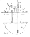
- Figure 3 is a representation of a drilling platform for use within the method of the invention;
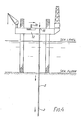
- Figure 4 is a representation of the Figure 3 platform during waste emplacement;
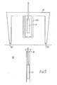
- Figure 5 is a representation of apparatus for handling waste within the method of the invention;
- Figure 6 is a representation of the Figure 3 platform showing the final encapsulation of waste;
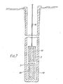
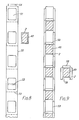
- Figure 7 is a representation of a means for waste emplacement within the method of the invention; and
- Figures 8 and 9 are representations of further means for waste emplacement within the method of the invention.
- As shown in Figures 1 and 2, at the site of origin (1) radioactive waste is sealed in pipe lengths e.g. steel drill piping, and the thus formed cylinders (2) are loaded into individual protective cells in a shielded container (3) sealed by a removable lid (7). A plurality of such containers (3) are then taken by rail (4) to a convenient port (5) where they are loaded onto a ship (6).
- Referring to Figure 3, at the offshore disposal site (10) the containers (3) are removed from the ship (6), e.g. by use of a crane (11) mounted on the platform deck (12), and placed in a storage bay (13) set into the platform deck. The bay (13) is radiation shielded and has a protective sliding cover (14).
- The platform carries a drilling derrick (15) extending over the side of the deck. Drilling operations may be carried out whilst containers are being off-loaded from the supply ship.
- Referring now to Figures 4, 5 and 6, the drilling derrick (15) may be either moveable on tracks or may be constructed so as to allow passage of a gantry crane (20) beneath it in order to allow access to the head of the bore hole (16). A gantry crane runs between the storage bay and the bore hole on tracks or skids (21) laid on the deck.
- The gantry crane (20) is provided with a shielded receptacle (22) for carrying the cylinders (2). The cover (14) of the storage bay (13) is removed, the receptacle (22) is placed over a cell in a container (3) and a cylinder (2) is drawn up into the receptacle (22). The cover (14) of the storage bay is replaced and the gantry crane (20) is moved to the head of the bore hole (16) where the cylinder (2) is released from the receptacle (22). The procedure is repeated to fill the bore hole with cylinders to a predetermined level. The top of the bore hole is then sealed (30), for example with concrete grouting, to contain the waste materials below the seabed.
- , Emptied containers (31) may be off-loaded from the platform to the supply vessel whilst cylinder disposal is in progress.
- In the method of the invention described above the waste cylinders are allowed to slide down the bore under the influence of their own weight and impeded by the hydrodynamic resistance of the fluid displaced from the bore. Alternative means for emplacement of cylinders are described below, by way of example, with reference to figures 7 to 9.
- In figure 7, waste material (40) (e.g. radioactive waste) in sealed canisters(2)is lowered by . a derrick mounted winch into the bore (16) on the end of a line of wire or cable (41). The line may, for example, be made of steel or aromatic polyamide resin - e.g. "Kevlar" (Registered Trade Mark). In order to improve the efficiency of operation of the method according to the invention it may be advantageous to provide a jack-up rig deck-hull (12) with more than one derrick (15) (e.g. two) for controlling winching of line (41).
- Thus canisters (2) may be lowered into more than one hole simultaneously.
- Offshore bore-holes may be drilled from bottom supported marine drilling platforms using a drill string formed by interconnection of individual standard length drill sections and having a drilling tool attached at the end; as the drill string is extended section by section the bore is drilled deeper.
- In a method according to the invention canisters of waste material may be attached as an extension at the end of a drill string, in place of the drilling tool, for lowering into a pre-drilled bore. For example, as shown in figures 8 and 9, a number of canisters may be interconnected to form a single unit of similar dimensions to a standard length drill section and attached to the string or, alternatively, a number of canisters of suitable diameter may be loaded into a tube having similar dimensions to a standard length drill section and attached to the string.
- In figure 8 noxious waste (40) is presealed in - a protective canister (2). A number of such canisters (2) are loaded into a casing(50) having suitably sized apertures (51). A mechanical catch (52) is provided if required to hold each canister (2) in place.
- Individual canisters (2) may be spaced apart by suitable diaphragms (53) within the casing (50). Thus each casing(50) acts as a magazine for loading with a number of canisters (2). The casing (50) is of comparable dimensions to a drill section and may have a suitable means (54) for attachment to a standard drill string or cable. In this case the canisters (2) have no structural load imposed on them as they are lowered down a disposal hole (16).
- In figure 9, noxious waste (40) is presealed in a protective canister (2) having complementary threaded connector means (58) at each end of the outer shell. A plurality of such canisters (2) may then be interconnected to provide sections of suitable length for attachment to a drill string. Where the waste material (40) is liable to generate heat (e.g. where the material (40) is high grade nuclear waste) spacer-sections (59) may be incorporated to aid heat disipation.
- In this case the canisters (2), and spacers (59) have a structural load imposed upon them as they are lowered down a disposal hole (16) and so they are reinforced to withstand both this load and the_torquing of the joints.
- The complete lengths for attachment to the drill string (e.g. about 10 m lengths) may be prepared either on shore or offshore on the platform as is most convenient.
- A number of such lengths are lowered into a disposal hole (16) at the end of a drill string and a conventional oil well tool is used to disconnect the sections containing waste canisters (2) and the drill string is withdrawn.
- It is emphasized that suitable existing drilling rigs could be used within the scope of the invention with little or no modification, although it is of course clear that when handling e.g. extremely radioactive waste, remote handling by automatic derricks, lead protective screens, constant wash-down of deck area during operation and other protective measures might be required. Some rig modification for the purposes of the invention can however be advantageous, a preferred such modification being that exemplified by figures 3 to5.
- A bottom-supported drilling platform is essential for the method of the invention since it provides a safe and stable base for storage and drilling. A jack-up drilling platform is particularly advantageous since it can be refloated and moved to a new offshore site when required.
Claims (11)
1. A method of disposing of waste materials characterised by drilling at least one bore hole (16) from a bottom-supported drilling platform (12) at an offshore site (10), transferring units (2) of waste material (40) from the platform to the head (16) of the bored hole, disposing units one upon another in the bore hole and sealing (30) the hole to contain the waste materials below the seabed.
2. A method according to claim 1 characterised by drilling at least one bore hole (16) from a bottom-supported drilling platform (12) at an offshore site (10), temporarily storing units (2) of waste material (40) on the platform, transferring the units from storage to the head (16) of a bored hole, disposing units one upon another in the bore hole and sealing (30) the hole to contain the waste materials below the seabed.
3. A method according to claim 1 wherein the bottom-supported platform (12) is a jack-up platform.
4. A method according to claim 1 wherein the units (2) of waste material (40) are allowed to slide down the bored hole under their own weight against the hydrodynamic resistance of fluid displaced from the hole.
5. A method according to claim 1 wherein individual units (2) of waste material (40) are lowered into the bored hole on a line (41).
6. A method according to claim 1 wherein a plurality of units (2) of waste material (40) are lowered into the bored hole together in a string.
7. A method according to claim 1 wherein each unit (2) of waste material (40) is in the form of a canister or sealed pipe length filled with the waste material.
8. A method according to claim 1 wherein a gantry crane (20) is movable across the platform deck (12) between a storage bay (13) for the units (2) of waste material (40) and the head (16) of the bored hole for collection of the units from storage and depositing them down the bored hole.
9. A method according to claim 8, wherein the platform (12) carries a gantry crane (20) movable between a storage bay (13) for the units (2) of waste material (40) and a position below a derrick (15) for collection of the units and depositing them in the bored hole or holes.
10. Apparatus for use in the method of claim 1 comprising a bottom-supported drilling platform (12) having drilling equipment including a drilling derrick
(15), storage facilities (13) for units (2) of waste materials (40) and means (20) for transferring the units from storage to the head of a bored disposal hole.
Applications Claiming Priority (6)
| Application Number | Priority Date | Filing Date | Title |
|---|---|---|---|
| GB8332176 | 1983-12-01 | ||
| GB838332176A GB8332176D0 (en) | 1983-12-01 | 1983-12-01 | Offshore waste disposal |
| GB8402954 | 1984-02-03 | ||
| GB848402954A GB8402954D0 (en) | 1984-02-03 | 1984-02-03 | Offshore waste disposal |
| GB8413562 | 1984-05-29 | ||
| GB08413562A GB2141575A (en) | 1983-05-26 | 1984-05-29 | Offshore waste disposal |
Publications (2)
| Publication Number | Publication Date |
|---|---|
| EP0154745A2 true EP0154745A2 (en) | 1985-09-18 |
| EP0154745A3 EP0154745A3 (en) | 1986-02-26 |
Family
ID=27262229
Family Applications (1)
| Application Number | Title | Priority Date | Filing Date |
|---|---|---|---|
| EP84308337A Withdrawn EP0154745A3 (en) | 1983-12-01 | 1984-11-30 | Offshore waste disposal |
Country Status (1)
| Country | Link |
|---|---|
| EP (1) | EP0154745A3 (en) |
Cited By (2)
| Publication number | Priority date | Publication date | Assignee | Title |
|---|---|---|---|---|
| DE3537816A1 (en) * | 1985-10-24 | 1987-05-07 | Strabag Bau Ag | Process for producing and operating a landfill site |
| CN104376886A (en) * | 2014-11-10 | 2015-02-25 | 中国海洋石油总公司 | Offshore nuclear power platform with cylindrical foundation bodies |
Family Cites Families (3)
| Publication number | Priority date | Publication date | Assignee | Title |
|---|---|---|---|---|
| DE2742340A1 (en) * | 1977-09-20 | 1979-03-22 | Erwin Bohinger | METHOD OF DISPOSAL OF PERSONAL HAZARDS, IN PARTICULAR RADIOACTIVE SUBSTANCES |
| US4400314A (en) * | 1980-10-14 | 1983-08-23 | Chevron Research Company | Method for the ultimate disposal of high level radioactive waste |
| GB2141575A (en) * | 1983-05-26 | 1984-12-19 | Copson George Collingwood | Offshore waste disposal |
-
1984
- 1984-11-30 EP EP84308337A patent/EP0154745A3/en not_active Withdrawn
Cited By (3)
| Publication number | Priority date | Publication date | Assignee | Title |
|---|---|---|---|---|
| DE3537816A1 (en) * | 1985-10-24 | 1987-05-07 | Strabag Bau Ag | Process for producing and operating a landfill site |
| CN104376886A (en) * | 2014-11-10 | 2015-02-25 | 中国海洋石油总公司 | Offshore nuclear power platform with cylindrical foundation bodies |
| CN104376886B (en) * | 2014-11-10 | 2017-01-18 | 中国海洋石油总公司 | Offshore nuclear power platform with cylindrical foundation bodies |
Also Published As
| Publication number | Publication date |
|---|---|
| EP0154745A3 (en) | 1986-02-26 |
Similar Documents
| Publication | Publication Date | Title |
|---|---|---|
| US7600570B2 (en) | Drilling rig placed on the sea bed and equipped for drilling of oil and gas wells | |
| US5202522A (en) | Deep well storage of radioactive material | |
| RU2719516C1 (en) | Bottom-based platform and method of creating drilling terminal for drilling in shallow-water shelf | |
| US3528254A (en) | Offshore platform structure and construction method | |
| US20120020742A1 (en) | Underwater Reinforced Concrete Silo for Oil Drilling and Production Applications | |
| CA1243495A (en) | Pressure balanced buoyant tether for subsea use | |
| US4861194A (en) | Waste disposal system | |
| JPS62215711A (en) | Ocean structure and method for anchoring the same | |
| US4815894A (en) | Construction and use of subsea bore holes | |
| WO1981003191A1 (en) | Offshore platform | |
| GB2141575A (en) | Offshore waste disposal | |
| US5733066A (en) | Apparatus and method for disposal of nuclear and other hazardous wastes | |
| US20130084136A1 (en) | Platform for controlled containment of hydrocarbons | |
| US4556343A (en) | Offshore oil storage and transfer facility | |
| US9109406B2 (en) | Method for removing a hydrocarbon production platform from sea | |
| EP0154745A2 (en) | Offshore waste disposal | |
| US2850271A (en) | Method of mining sulfur located underneath bodies of water | |
| JP4562927B2 (en) | Load test method for work ships | |
| CA2058789C (en) | Method of installing well conductors | |
| CN116905385B (en) | Pier pre-buried construction process based on drilling method | |
| Garside et al. | MARS TLP-lntegration and Installation | |
| US7525112B2 (en) | Method and apparatus for permanent and safe disposal of radioactive waste | |
| GB2157061A (en) | Radioactive material handling equipment | |
| US20030216606A1 (en) | Method and apparatus for permanent and safe disposal of radioactive waste | |
| GB2286284A (en) | Radioactive waste disposal |
Legal Events
| Date | Code | Title | Description |
|---|---|---|---|
| PUAI | Public reference made under article 153(3) epc to a published international application that has entered the european phase |
Free format text: ORIGINAL CODE: 0009012 |
|
| AK | Designated contracting states |
Designated state(s): BE DE FR NL |
|
| PUAL | Search report despatched |
Free format text: ORIGINAL CODE: 0009013 |
|
| AK | Designated contracting states |
Designated state(s): BE DE FR NL |
|
| STAA | Information on the status of an ep patent application or granted ep patent |
Free format text: STATUS: THE APPLICATION IS DEEMED TO BE WITHDRAWN |
|
| 18D | Application deemed to be withdrawn |
Effective date: 19870129 |
|
| RIN1 | Information on inventor provided before grant (corrected) |
Inventor name: COPSON, ALEXANDER GEORGE |