EP0154733A1 - Transfer apparatus - Google Patents
Transfer apparatus Download PDFInfo
- Publication number
- EP0154733A1 EP0154733A1 EP84301608A EP84301608A EP0154733A1 EP 0154733 A1 EP0154733 A1 EP 0154733A1 EP 84301608 A EP84301608 A EP 84301608A EP 84301608 A EP84301608 A EP 84301608A EP 0154733 A1 EP0154733 A1 EP 0154733A1
- Authority
- EP
- European Patent Office
- Prior art keywords
- bars
- layer
- rods
- vessel
- layers
- Prior art date
- Legal status (The legal status is an assumption and is not a legal conclusion. Google has not performed a legal analysis and makes no representation as to the accuracy of the status listed.)
- Withdrawn
Links
- 238000012856 packing Methods 0.000 claims abstract description 15
- 239000011343 solid material Substances 0.000 claims abstract description 12
- 239000012530 fluid Substances 0.000 claims abstract description 6
- 239000007787 solid Substances 0.000 claims description 15
- 239000011236 particulate material Substances 0.000 claims description 10
- 239000000919 ceramic Substances 0.000 claims description 4
- 229910010293 ceramic material Inorganic materials 0.000 claims description 4
- 230000000284 resting effect Effects 0.000 claims description 4
- 239000007789 gas Substances 0.000 description 17
- 239000004576 sand Substances 0.000 description 11
- 238000010276 construction Methods 0.000 description 5
- NINIDFKCEFEMDL-UHFFFAOYSA-N Sulfur Chemical compound [S] NINIDFKCEFEMDL-UHFFFAOYSA-N 0.000 description 4
- 239000005864 Sulphur Substances 0.000 description 4
- 239000003054 catalyst Substances 0.000 description 3
- 238000000034 method Methods 0.000 description 3
- 239000011449 brick Substances 0.000 description 2
- 238000006243 chemical reaction Methods 0.000 description 2
- 229910003460 diamond Inorganic materials 0.000 description 2
- 239000010432 diamond Substances 0.000 description 2
- 230000000694 effects Effects 0.000 description 2
- 229940077002 keystone Drugs 0.000 description 2
- 239000000126 substance Substances 0.000 description 2
- 230000002745 absorbent Effects 0.000 description 1
- 239000002250 absorbent Substances 0.000 description 1
- 230000000903 blocking effect Effects 0.000 description 1
- 238000004140 cleaning Methods 0.000 description 1
- 238000002485 combustion reaction Methods 0.000 description 1
- 238000001816 cooling Methods 0.000 description 1
- 238000010586 diagram Methods 0.000 description 1
- 239000011521 glass Substances 0.000 description 1
- 239000011819 refractory material Substances 0.000 description 1
- XLYOFNOQVPJJNP-UHFFFAOYSA-N water Substances O XLYOFNOQVPJJNP-UHFFFAOYSA-N 0.000 description 1
Images
Classifications
-
- F—MECHANICAL ENGINEERING; LIGHTING; HEATING; WEAPONS; BLASTING
- F28—HEAT EXCHANGE IN GENERAL
- F28C—HEAT-EXCHANGE APPARATUS, NOT PROVIDED FOR IN ANOTHER SUBCLASS, IN WHICH THE HEAT-EXCHANGE MEDIA COME INTO DIRECT CONTACT WITHOUT CHEMICAL INTERACTION
- F28C3/00—Other direct-contact heat-exchange apparatus
- F28C3/10—Other direct-contact heat-exchange apparatus one heat-exchange medium at least being a fluent solid, e.g. a particulate material
- F28C3/12—Other direct-contact heat-exchange apparatus one heat-exchange medium at least being a fluent solid, e.g. a particulate material the heat-exchange medium being a particulate material and a gas, vapour, or liquid
- F28C3/14—Other direct-contact heat-exchange apparatus one heat-exchange medium at least being a fluent solid, e.g. a particulate material the heat-exchange medium being a particulate material and a gas, vapour, or liquid the particulate material moving by gravity, e.g. down a tube
-
- B—PERFORMING OPERATIONS; TRANSPORTING
- B01—PHYSICAL OR CHEMICAL PROCESSES OR APPARATUS IN GENERAL
- B01D—SEPARATION
- B01D53/00—Separation of gases or vapours; Recovering vapours of volatile solvents from gases; Chemical or biological purification of waste gases, e.g. engine exhaust gases, smoke, fumes, flue gases, aerosols
- B01D53/02—Separation of gases or vapours; Recovering vapours of volatile solvents from gases; Chemical or biological purification of waste gases, e.g. engine exhaust gases, smoke, fumes, flue gases, aerosols by adsorption, e.g. preparative gas chromatography
- B01D53/06—Separation of gases or vapours; Recovering vapours of volatile solvents from gases; Chemical or biological purification of waste gases, e.g. engine exhaust gases, smoke, fumes, flue gases, aerosols by adsorption, e.g. preparative gas chromatography with moving adsorbents, e.g. rotating beds
- B01D53/08—Separation of gases or vapours; Recovering vapours of volatile solvents from gases; Chemical or biological purification of waste gases, e.g. engine exhaust gases, smoke, fumes, flue gases, aerosols by adsorption, e.g. preparative gas chromatography with moving adsorbents, e.g. rotating beds according to the "moving bed" method
-
- B—PERFORMING OPERATIONS; TRANSPORTING
- B01—PHYSICAL OR CHEMICAL PROCESSES OR APPARATUS IN GENERAL
- B01J—CHEMICAL OR PHYSICAL PROCESSES, e.g. CATALYSIS OR COLLOID CHEMISTRY; THEIR RELEVANT APPARATUS
- B01J8/00—Chemical or physical processes in general, conducted in the presence of fluids and solid particles; Apparatus for such processes
- B01J8/08—Chemical or physical processes in general, conducted in the presence of fluids and solid particles; Apparatus for such processes with moving particles
- B01J8/12—Chemical or physical processes in general, conducted in the presence of fluids and solid particles; Apparatus for such processes with moving particles moved by gravity in a downward flow
- B01J8/125—Chemical or physical processes in general, conducted in the presence of fluids and solid particles; Apparatus for such processes with moving particles moved by gravity in a downward flow with multiple sections one above the other separated by distribution aids, e.g. reaction and regeneration sections
-
- F—MECHANICAL ENGINEERING; LIGHTING; HEATING; WEAPONS; BLASTING
- F28—HEAT EXCHANGE IN GENERAL
- F28D—HEAT-EXCHANGE APPARATUS, NOT PROVIDED FOR IN ANOTHER SUBCLASS, IN WHICH THE HEAT-EXCHANGE MEDIA DO NOT COME INTO DIRECT CONTACT
- F28D19/00—Regenerative heat-exchange apparatus in which the intermediate heat-transfer medium or body is moved successively into contact with each heat-exchange medium
- F28D19/02—Regenerative heat-exchange apparatus in which the intermediate heat-transfer medium or body is moved successively into contact with each heat-exchange medium using granular particles
-
- B—PERFORMING OPERATIONS; TRANSPORTING
- B01—PHYSICAL OR CHEMICAL PROCESSES OR APPARATUS IN GENERAL
- B01D—SEPARATION
- B01D2257/00—Components to be removed
- B01D2257/30—Sulfur compounds
- B01D2257/302—Sulfur oxides
-
- B—PERFORMING OPERATIONS; TRANSPORTING
- B01—PHYSICAL OR CHEMICAL PROCESSES OR APPARATUS IN GENERAL
- B01D—SEPARATION
- B01D2257/00—Components to be removed
- B01D2257/30—Sulfur compounds
- B01D2257/304—Hydrogen sulfide
-
- B—PERFORMING OPERATIONS; TRANSPORTING
- B01—PHYSICAL OR CHEMICAL PROCESSES OR APPARATUS IN GENERAL
- B01D—SEPARATION
- B01D2259/00—Type of treatment
- B01D2259/40—Further details for adsorption processes and devices
- B01D2259/40011—Methods relating to the process cycle in pressure or temperature swing adsorption
- B01D2259/40077—Direction of flow
- B01D2259/40081—Counter-current
-
- B—PERFORMING OPERATIONS; TRANSPORTING
- B01—PHYSICAL OR CHEMICAL PROCESSES OR APPARATUS IN GENERAL
- B01D—SEPARATION
- B01D2259/00—Type of treatment
- B01D2259/40—Further details for adsorption processes and devices
- B01D2259/402—Further details for adsorption processes and devices using two beds
Definitions
- the present invention relates to transfer apparatus which is suitable for heat and/or mass transfer.
- heat and/or mass transfer apparatus Various forms of heat and/or mass transfer apparatus have been proposed. Most heat transfer apparatuses include a series of plates, tubes or the like, one fluid flowing on one side of the plate or pipe and another on the other. Such apparatus is generally satisfactory but it is not entirely efficient and it is not very suitable for use in mass transfer.
- the packing comprises a plurality of layers of bars extending generally horizontally across the vessel, the bars of each layer being substantially parallel to one another and having a spacing between adjacent bars which is substantially the same for the bars of that layer, the parallel bars of each layer extending transversely at an angle to the parallel bars of the adjacent layer or layers.
- the spacing between the bars of a layer is preferably within the range 0.75 to 1.5 times the width of the bars so that the space available between the bars is approximately the same as the blocking effect of the bars.
- the ratio of the height to width of each bar is preferably in the range of 0.5 to 2 and is advantageously of the order of 1.
- the rods of each layer are advantageously arranged substantially perpendicular to the rods of the adjacent layer or layers above or below.
- the bars of one layer may then be placed parallel to the bars of the layer two above or two below.
- the bars of the layer two below or two above can then have a lateral shift with respect to those of the one layer and thereby particulate material falling between the bars of the said one layer will inevitably hit the bars of the layer below particularly if the shift is by an amount in the range of 0.35 to 0.8 times the width of the bars and preferably half the width.
- the rods preferably have an upper surface which is inclined at an angle which is less than the angle of repose of the particulate material. This can be achieved by having the upper surface as an inverted V section, for example the rod being of a square cross-section with one corner of the square uppermost.
- the rods can be circular, or elliptical, although this is less likely to provide the desired effect because of the possibility of the particulate material stacking on top of the bars.
- the bars are preferably of ceramic material and an arched ceramic support structure may be located below the lowermost of the layers of rods, the rods of said lowermost layers resting on and being supported by the structure.
- the rods of each layer thereabove will rest on and be supported by the rods of the layer immediately below them.
- a plurality of laterally spaced Y cross-section separator member which can have a hollow interior for the downflow of solid material.
- the solid can be separated from the gas which can flow upwardly between the separator members.
- At least one of the separator members may be arranged higher than the others adjacent thereto, so that the arms of the various separator members overlap and together cover the whole area of the chamber, so that all the solid material falling will be picked up by the arms.
- FIG. 1 there is illustrated therein an apparatus comprising first and second vessels 10, 12, the first vessel having a particulate solid, e.g. sand, inlet 14 and a solid outlet 15.
- This outlet 15 is connected to an inlet 16 of the second vessel 12 which, in turn, has a solid outlet 18.
- Solid material from the second vessel can be fed via a conveyor, illustrated schematically at 20, back to the inlet 14 of the first vessel 10.
- Vessel 10 is provided with a hot gas inlet 22 and a cold gas outlet 24, while the second vessel is provided with a lower cold air inlet 26 and a hot air outlet 28.
- Each vessel is provided with a packing intermediate the solid inlet and outlet the packing of vessel 10 being indicated by the reference 30 and that of the vessel 12 by the reference 32.
- particulate material such as sand
- sand is allowed to fall downwardly through the first vessel having entered inlet 14 and it is distributed within the vessel to be caused to flow in a uniform manner across the full cross-sectional width of the vessel 10 by the packing 30. It is caused to react thermally with the hot gas entering at 22. As the sand is cold, a heat exchange is produced so that the sand is heated and the hot gas is cooled. By the time it reaches the top of the vessel 10 the gas is relatively cold and is discharged as a cold gas at 24.
- the vessel 12 In order to recover the heat from the sand, the vessel 12 is used in a similar, but reverse, way. Cold air is caused to enter at 26 and the hot sand at 16.
- the packing 32 has a similar effect to the packing 30 and heat exchange takes place between the air and sand so that the sand is cooled and the air is heated being discharged at 28.
- the cold sand is then transferred by conveyor 20 to the inlet 14 so that the process can be carried out substantially continuously.
- Such a system could be used, for example, to obtain a cooling of the exhaust gases of any suitable process, such as a glass or like oven and the recovered heat can be used to heat up the incoming air of combustion for the oven.
- a very high efficiency of heat exchange can be achieved because of the even distribution of the sand, and there is little or no scaling.
- the apparatus can be used for many different purposes and is not only involved as a heat exchange apparatus, but can also be used in a chemical exchange.
- the apparatus could be used to remove sulphur in chemical systems with the reaction of H 2 S and S0 2 to give sulphur and water, so that the sulphur can be removed.
- This can be applied, for example, in the Claus of tail gases where H 2 S and S02 exist and on gas streams containing either H 2 S or 50 2 , where necessary feeding one of these gases where only the other is present.
- the apparatus can be used for heat transfer as indicated above, for mass transfer, without a chemical reaction, e.g. for gas cleaning with a solid which is an absorbant. It can be used in mass transfer with the solid being a catalyst.
- Equilibrium can be shif ted by removing a component of the solid e.g. in sulphur removal mentioned above.
- the packing is in the form of a plurality of layers of bars extending generally horizontally of the vessel, the bars of each layer being substantially parallel to one another and having a spacing between adjacent bars which is substantially the same for the bars of that layer, the parallel bars of each layer extending transversely at an angle to the parallel bars of the adjacent layer or layers.
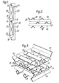
- Figure 2 illustrated such a construction in which the bars are indicated as being an inverted V cross-sections bars 40, 42, 44, 46.
- the bars 40 extend parallel to one another and have a constant spacing therebetween and the bars 42 extend transversely thereto, for example at right angles thereto.
- the third layer of bars 44 extends transversely to the bars 42 and preferably perpendicular thereto so that they are parallel to the bars 40 and are preferably arranged so that they are between the bars 40.
- the bars 46 are transverse to the bars 44 and preferably parallel to the bars 42 and again are disposed offset from the bars 42.
- the apparatus in Figure 2 also illustrates bars 48 which are placed substantially below the bars 40. At the edge of the apparatus there are indicated deflector bars 50, 52.
- Figure 3 illustrated a packing construction which is generally similar, but the bars 60, 64, 66, 68 are of generally square cross-section with one corner of each square uppermost so that the bars are arranged rather in the manner of a diamond.
- the bars of the third layer (bars 66), are offset from, and indeed between, the bars 60 and bars 68 are offset from and between the bars 64.
- such an array of bars provides a very even distribution of downflowing particulate material, such as sand, catalyst, absorbent or the like so that the particulate material is evenly distributed across the full cross-section of the vessel (not shown in Figure 3). This ensures a very good heat and/or mass transfer between the solid particulate material and the upflowing gas.
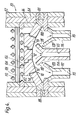
- Figure 4 a further construction is illustrated showing how the bars, similar to those of Figure 3, can be supported.
- the construction of Figure 4 is intended for use in a high temperature environment and most of the parts illustrated are formed of a ceramic refractory material.
- the vessel 80 includes an outer wall 82 and two inner liners 84, 86.
- Support bars 88 extend along each side of the vessel and serve to support an arched construction indicated generally by the reference 90.
- This includes a key stone 92 and suitable arch bricks 94, 96, 98, 100 and carried on the ring 88.
- the upper surfaces of the key stone 92 and of the bricks 96, 98 extend in a horizontal plane and mounted on a thus formed flat upper surface are a layer of generally diamond shaped bars 102, formed of a ceramic material, for example, and provided with upper and lower flat corner parts 104, 106. These serve to maintain the bars in the configuration illustrated.
- a transversely extending layer of bars 108 is mounted on the layer of bars 102 only one of which, of course, can be seen in the drawing, these bars are generally similar to the bars of layer 102.
- a third layer 110 of again similar bars is provided, these again, as in Figure 3, being offset laterally so as to lie approximately between the bars of the layer 102.
- each of these is of generally Y cross.section having a hollow interior 115 for the downflow of solid material.
- the central separator member 114 is higher than the separator members 112, 116 adjacent thereto, and the arms 118 are of the central member 114 overlap the arms 120 of the members 112, 116, so that solid material falling downwardly in all parts of the cross-section of the chamber within the vessel 80 fall into one of the separator members, which collectively span the whole of the cross-section.
- Solid material flowing through the hollow interior 115 can be discharged and collected as explained with reference to Figure 1. Upflowing gas passes between the arms of the separator member 112, 116 and the arms 118 of the central separator member 114. This arrangement therefore separates the gas from the solid in a satisfactory manner.
- the apparatus has been described as having the bars of one layer resting directly on those of the layer below.
- the bars of one layer can be mounted with a spacing compared to those of the layer above and/or below. This spacing is preferably no more than 10 times the vertical height of the bars.
Landscapes
- Engineering & Computer Science (AREA)
- Chemical & Material Sciences (AREA)
- Mechanical Engineering (AREA)
- General Engineering & Computer Science (AREA)
- Chemical Kinetics & Catalysis (AREA)
- Analytical Chemistry (AREA)
- General Chemical & Material Sciences (AREA)
- Oil, Petroleum & Natural Gas (AREA)
- Physics & Mathematics (AREA)
- Thermal Sciences (AREA)
- Organic Chemistry (AREA)
- Devices And Processes Conducted In The Presence Of Fluids And Solid Particles (AREA)
Abstract
Transfer apparatus comprising a vessel (10, 12) having an inlet (14, 16) and a outlet (15, 18) for particulate solid material and an inlet (22, 26) and outlet (24, 28) for fluid to flow in countercurrent or cocurrent to the solid material, and a packing (30, 32) within the vessel, the packing including a plurality of layers of bars (60 to 68) extending generally horizontally across the vessel, the bars of each layer being substantially parallel to one another and having a spacing between adjacent bars which is substantially the same for the bars of said layer. The parallel bars of each layer extend transversely, preferably perpendicular, to the parallel bars of the adjacent layer of layers.
Description
- The present invention relates to transfer apparatus which is suitable for heat and/or mass transfer.
- Various forms of heat and/or mass transfer apparatus have been proposed. Most heat transfer apparatuses include a series of plates, tubes or the like, one fluid flowing on one side of the plate or pipe and another on the other. Such apparatus is generally satisfactory but it is not entirely efficient and it is not very suitable for use in mass transfer.
- It has been proposed to provide a vessel having an inlet and a outlet for particulate solid material, a inlet and an outlet for fluid which flows in countercurrent or cocurrent through the vessel and a packing within the vessel. The solid material is used as a heat transfer medium and can also be used in mass transfer for example as a catalyst.
- Such apparatus while having some advantages over the plate or pipe type has not proved entirely satisfactory because of channelling within the vessel.
- It is now proposed, according to the present invention, for the packing to comprise a plurality of layers of bars extending generally horizontally across the vessel, the bars of each layer being substantially parallel to one another and having a spacing between adjacent bars which is substantially the same for the bars of that layer, the parallel bars of each layer extending transversely at an angle to the parallel bars of the adjacent layer or layers.
- It has been found that such a packing arrangement ensures a very even distribution of fluid and the particulate material giving a good pattern of flow for effective transfer.
- The spacing between the bars of a layer is preferably within the range 0.75 to 1.5 times the width of the bars so that the space available between the bars is approximately the same as the blocking effect of the bars.
- Similarly the ratio of the height to width of each bar is preferably in the range of 0.5 to 2 and is advantageously of the order of 1.
- The rods of each layer are advantageously arranged substantially perpendicular to the rods of the adjacent layer or layers above or below. The bars of one layer may then be placed parallel to the bars of the layer two above or two below. The bars of the layer two below or two above can then have a lateral shift with respect to those of the one layer and thereby particulate material falling between the bars of the said one layer will inevitably hit the bars of the layer below particularly if the shift is by an amount in the range of 0.35 to 0.8 times the width of the bars and preferably half the width.
- The rods preferably have an upper surface which is inclined at an angle which is less than the angle of repose of the particulate material. This can be achieved by having the upper surface as an inverted V section, for example the rod being of a square cross-section with one corner of the square uppermost. Alternatively the rods can be circular, or elliptical, although this is less likely to provide the desired effect because of the possibility of the particulate material stacking on top of the bars.
- When the apparatus is to be used in a very high temperature process, the bars are preferably of ceramic material and an arched ceramic support structure may be located below the lowermost of the layers of rods, the rods of said lowermost layers resting on and being supported by the structure. The rods of each layer thereabove will rest on and be supported by the rods of the layer immediately below them. Advantageously below the support structure there is provided a plurality of laterally spaced Y cross-section separator member which can have a hollow interior for the downflow of solid material. Thus the solid can be separated from the gas which can flow upwardly between the separator members.At least one of the separator members may be arranged higher than the others adjacent thereto, so that the arms of the various separator members overlap and together cover the whole area of the chamber, so that all the solid material falling will be picked up by the arms.
- In order that the present invention may more readily be understood, the following description is given, merely by way of example, reference being made to the accompanying drawings in which:-
- Figure 1 is a schematic diagram of one embodiment of apparatus according to the present invention;
- Figure 2 is a cross-section illustrating one particular form of bar arrangement;
- Figure 3 is a perspective view illustrating a second form of bar arrangement; and
- Figure 4 is a cross-section through the lower part of a further form of an apparatus according to the invention.
- Referring first to Figure 1 there is illustrated therein an apparatus comprising first and
second vessels inlet 14 and asolid outlet 15. Thisoutlet 15 is connected to an inlet 16 of thesecond vessel 12 which, in turn, has asolid outlet 18. Solid material from the second vessel can be fed via a conveyor, illustrated schematically at 20, back to theinlet 14 of thefirst vessel 10. - Vessel 10 is provided with a hot gas inlet 22 and a cold gas outlet 24, while the second vessel is provided with a lower cold air inlet 26 and a
hot air outlet 28. - Each vessel is provided with a packing intermediate the solid inlet and outlet the packing of
vessel 10 being indicated by thereference 30 and that of thevessel 12 by thereference 32. - In use, particulate material, such as sand, is allowed to fall downwardly through the first vessel having entered
inlet 14 and it is distributed within the vessel to be caused to flow in a uniform manner across the full cross-sectional width of thevessel 10 by thepacking 30. It is caused to react thermally with the hot gas entering at 22. As the sand is cold, a heat exchange is produced so that the sand is heated and the hot gas is cooled. By the time it reaches the top of thevessel 10 the gas is relatively cold and is discharged as a cold gas at 24. - In order to recover the heat from the sand, the
vessel 12 is used in a similar, but reverse, way. Cold air is caused to enter at 26 and the hot sand at 16. Thepacking 32 has a similar effect to thepacking 30 and heat exchange takes place between the air and sand so that the sand is cooled and the air is heated being discharged at 28. The cold sand is then transferred byconveyor 20 to theinlet 14 so that the process can be carried out substantially continuously. - Such a system could be used, for example, to obtain a cooling of the exhaust gases of any suitable process, such as a glass or like oven and the recovered heat can be used to heat up the incoming air of combustion for the oven.
- A very high efficiency of heat exchange can be achieved because of the even distribution of the sand, and there is little or no scaling.
- The apparatus can be used for many different purposes and is not only involved as a heat exchange apparatus, but can also be used in a chemical exchange. For example, it is contemplated that the apparatus could be used to remove sulphur in chemical systems with the reaction of H2S and S02 to give sulphur and water, so that the sulphur can be removed. This can be applied, for example, in the Claus of tail gases where H2S and S02 exist and on gas streams containing either H2S or 502, where necessary feeding one of these gases where only the other is present.
- The apparatus can be used for heat transfer as indicated above, for mass transfer, without a chemical reaction, e.g. for gas cleaning with a solid which is an absorbant. It can be used in mass transfer with the solid being a catalyst.
- Equilibrium can be shif ted by removing a component of the solid e.g. in sulphur removal mentioned above.
- In order that the flow of solid and gas is satisfactory to achieve these results, according to the present invention, the packing is in the form of a plurality of layers of bars extending generally horizontally of the vessel, the bars of each layer being substantially parallel to one another and having a spacing between adjacent bars which is substantially the same for the bars of that layer, the parallel bars of each layer extending transversely at an angle to the parallel bars of the adjacent layer or layers.
- Figure 2 illustrated such a construction in which the bars are indicated as being an inverted
V cross-sections bars 40, 42, 44, 46. The bars 40 extend parallel to one another and have a constant spacing therebetween and the bars 42 extend transversely thereto, for example at right angles thereto. - The third layer of bars 44 extends transversely to the bars 42 and preferably perpendicular thereto so that they are parallel to the bars 40 and are preferably arranged so that they are between the bars 40. Again the
bars 46 are transverse to the bars 44 and preferably parallel to the bars 42 and again are disposed offset from the bars 42. The apparatus in Figure 2 also illustratesbars 48 which are placed substantially below the bars 40. At the edge of the apparatus there are indicateddeflector bars - Figure 3 illustrated a packing construction which is generally similar, but the
bars bars 68 are offset from and between thebars 64. It will be appreciated that such an array of bars provides a very even distribution of downflowing particulate material, such as sand, catalyst, absorbent or the like so that the particulate material is evenly distributed across the full cross-section of the vessel (not shown in Figure 3). This ensures a very good heat and/or mass transfer between the solid particulate material and the upflowing gas. - Referring now to Figure 4 a further construction is illustrated showing how the bars, similar to those of Figure 3, can be supported. The construction of Figure 4 is intended for use in a high temperature environment and most of the parts illustrated are formed of a ceramic refractory material.
- The
vessel 80 includes anouter wall 82 and twoinner liners Support bars 88 extend along each side of the vessel and serve to support an arched construction indicated generally by thereference 90. This includes a key stone 92 andsuitable arch bricks ring 88. The upper surfaces of the key stone 92 and of thebricks bars 102, formed of a ceramic material, for example, and provided with upper and lowerflat corner parts bars 102 is a transversely extending layer ofbars 108 only one of which, of course, can be seen in the drawing, these bars are generally similar to the bars oflayer 102. Athird layer 110 of again similar bars is provided, these again, as in Figure 3, being offset laterally so as to lie approximately between the bars of thelayer 102. There will be further bars stacked on top of one another alternately one way, and the other. The thus formed packing again provides a very even distribution without any fear of channelling by either the solid or the gas and therefore gives a high measure of heat and/or mass transfer. - Positioned below the arch 90 are three
separator members hollow interior 115 for the downflow of solid material. Thecentral separator member 114 is higher than theseparator members arms 118 are of thecentral member 114 overlap thearms 120 of themembers vessel 80 fall into one of the separator members, which collectively span the whole of the cross-section. Solid material flowing through thehollow interior 115 can be discharged and collected as explained with reference to Figure 1. Upflowing gas passes between the arms of theseparator member arms 118 of thecentral separator member 114. This arrangement therefore separates the gas from the solid in a satisfactory manner. - Because it is sometimes desirable to have the bars formed of ceramic material if very high temperatures are encountered the arch structure of Figure 4 is particularly useful in providing adequate support for such ceramic members which are not capable of withstanding any level of tension.
- It will be appreciated that the apparatus of the present invention in all the embodiments illustrated is particularly efficient having no dead zones so that a good degree of heat and/or mass transfer can be achieved.
- The apparatus has been described as having the bars of one layer resting directly on those of the layer below. In fact the bars of one layer can be mounted with a spacing compared to those of the layer above and/or below. This spacing is preferably no more than 10 times the vertical height of the bars.
Claims (13)
1. Transfer apparatus comprising a vessel (10,12) defining a contact chamber, an inlet (14,16) to said vessel for solid particulate material, an outlet (15,18) from said vessel for solid particulate material, a fluid inlet (22,26), a fluid outlet (24,28) and a packing within said vessel, characterised in that said packing comprises a plurality of layers of bars (40-48, 60- 68, 102, 108, 110) extending generally horizontally across said vessel, the bars of each layer being substantially the same for the bars of said layer, the parallel bars of each layer extending transversely at an angle to the parallel bars of the adjacent layer of layers.
2. Apparatus according to claim 1, characterised in that the spacing between the bars of a layer is in the range 0.75 to 1.5 times the width of the bars of said layer.
3. Apparatus according to claim 1 or 2, characterised in that the ration of the height/width of each bar is in the range 0.5 to 2.0.
4. Apparatus according to any preceding claim, characterised in that the rods of each layer are arranged substantially perpendicular to the rods of the adjacent layer or layers above and/or below.
5. Apparatus according to any preceding claim, characterised in that the bars of one layer are parallel to the bars of the layer two above or two below, the bars of said layer two above or two below having a lateral shift with respect to those of said one layer.
6. Apparatus according to claim 5, characterised in that said lateral shift is by an amount in the range 0.35 to 0.8 times the width of the bars.
7. Apparatus according to any preceding claim, characterised in that the rods have an upper surface which is of inverted V cross-section.
8. Apparatus according to claim 7, characterised in that the rods are of square cross-section, with one corner of the square uppermost.
9. Apparatus according to any preceding claim, characterised in that the rods are formed of a ceramic material.
10. Apparatus according to any preceding claim, characterised in that an arched ceramic support structure (90) is located below the lowermost of said layers (102) of rods, the rods of said lowermost layer resting on and being supported by said structure, the rods of each layer (108, 110) thereabove resting on and being supported by the rods of the layer immediately therebelow.
11. Apparatus according to claim 10, characterised in that, below said support structure (90) there is provided a plurality of laterally spaced Y cross-section separator members (112, 114, 116) having a hollow interior (115) for the downflow of solid material, whereby the solid is separated from the gas which can flow upwardly between said separator member.
12. Apparatus according to claim 11, characterised in that at least one (114) of said separator members is arranged higher than the separator member or members (112, 116) adjacent thereto, whereby the arms (118) of said at least one separator member overlap those (120) of those of said adjacent separator member or members, to enable solid material falling in all parts of the cross-section of the chamber to fall into one of said separator members.
13. Apparatus according to any preceding claim characterised in that the vettical spacing between the layers of bars is no, more than 10 times the vertical height of the bars.
Priority Applications (6)
| Application Number | Priority Date | Filing Date | Title |
|---|---|---|---|
| NL8203577A NL8203577A (en) | 1984-03-09 | 1982-09-15 | APPARATUS FOR CONTACTING GAS OR VAPOR FLOW WITH EACH OTHER AND A RAIL FALLING FROM A GRANULAR SOLID, GRID PACKING FOR SUCH A DEVICE AND APPARATUS FOR THE TRANSFER OF HOT GAS OF HOT GAS TO A COLD GAS GRANULAR SOLID. |
| EP84301608A EP0154733A1 (en) | 1984-03-09 | 1984-03-09 | Transfer apparatus |
| AU25525/84A AU2552584A (en) | 1984-03-09 | 1984-03-12 | Heat and mass transfer apparatus with supported solid particles in gas stream |
| US06/589,635 US4535551A (en) | 1982-09-15 | 1984-03-14 | Transfer apparatus |
| JP59050145A JPS60196595A (en) | 1984-03-09 | 1984-03-15 | Transfer device |
| ZA842164A ZA842164B (en) | 1984-03-09 | 1984-03-23 | Transfer apparatus |
Applications Claiming Priority (1)
| Application Number | Priority Date | Filing Date | Title |
|---|---|---|---|
| EP84301608A EP0154733A1 (en) | 1984-03-09 | 1984-03-09 | Transfer apparatus |
Publications (1)
| Publication Number | Publication Date |
|---|---|
| EP0154733A1 true EP0154733A1 (en) | 1985-09-18 |
Family
ID=8192586
Family Applications (1)
| Application Number | Title | Priority Date | Filing Date |
|---|---|---|---|
| EP84301608A Withdrawn EP0154733A1 (en) | 1982-09-15 | 1984-03-09 | Transfer apparatus |
Country Status (6)
| Country | Link |
|---|---|
| US (1) | US4535551A (en) |
| EP (1) | EP0154733A1 (en) |
| JP (1) | JPS60196595A (en) |
| AU (1) | AU2552584A (en) |
| NL (1) | NL8203577A (en) |
| ZA (1) | ZA842164B (en) |
Cited By (3)
| Publication number | Priority date | Publication date | Assignee | Title |
|---|---|---|---|---|
| EP2717986A4 (en) * | 2011-06-09 | 2014-11-12 | Stanford Res Inst Int | COUNTER-CURRENT FLOW PROCESS USING FALL MICROBILLS TO SEPARATE GASEOUS MIXTURES |
| CN104697358A (en) * | 2013-12-05 | 2015-06-10 | 北新集团建材股份有限公司 | Vertical-type powder cooler |
| WO2019212336A1 (en) * | 2018-04-30 | 2019-11-07 | C2Ca Technology B.V. | Cement waste recycling device and method of recycling cement waste |
Families Citing this family (7)
| Publication number | Priority date | Publication date | Assignee | Title |
|---|---|---|---|---|
| NL8203577A (en) * | 1984-03-09 | 1984-04-02 | Energy Equipment Engineering B | APPARATUS FOR CONTACTING GAS OR VAPOR FLOW WITH EACH OTHER AND A RAIL FALLING FROM A GRANULAR SOLID, GRID PACKING FOR SUCH A DEVICE AND APPARATUS FOR THE TRANSFER OF HOT GAS OF HOT GAS TO A COLD GAS GRANULAR SOLID. |
| CH666827A5 (en) * | 1985-06-18 | 1988-08-31 | Friedrich Curtius Dipl Ing | METHOD FOR DRY CLEANING SMOKE GASES. |
| US4786368A (en) * | 1985-09-30 | 1988-11-22 | Amoco Corporation | Static mixer retorting of oil shale |
| US6550960B2 (en) | 2000-10-11 | 2003-04-22 | The Procter & Gamble Company | Apparatus for in-line mixing and process of making such apparatus |
| DE10357696B4 (en) * | 2003-12-09 | 2007-12-13 | Clausthaler Umwelttechnikinstitut Gmbh, (Cutec-Institut) | A method for the treatment of organosilicon contents or accompanying substances containing exhaust gases and an apparatus therefor |
| DE102005007289A1 (en) * | 2005-02-17 | 2006-10-12 | Epc Engineering Consulting Gmbh | Distributor bottom for columns |
| CN102022932A (en) * | 2010-09-09 | 2011-04-20 | 郑用琦 | Solid-liquid heat exchanger |
Citations (4)
| Publication number | Priority date | Publication date | Assignee | Title |
|---|---|---|---|---|
| US2536099A (en) * | 1947-08-18 | 1951-01-02 | American Metal Co Ltd | Means for forming stages in fluidized masses |
| US4371335A (en) * | 1981-04-17 | 1983-02-01 | Paraho Corporation | Zone separator for multiple zone vessels |
| GB2116869A (en) * | 1982-03-19 | 1983-10-05 | Delbag Luftfilter Gmbh | Moving bed filter |
| NL8203577A (en) * | 1984-03-09 | 1984-04-02 | Energy Equipment Engineering B | APPARATUS FOR CONTACTING GAS OR VAPOR FLOW WITH EACH OTHER AND A RAIL FALLING FROM A GRANULAR SOLID, GRID PACKING FOR SUCH A DEVICE AND APPARATUS FOR THE TRANSFER OF HOT GAS OF HOT GAS TO A COLD GAS GRANULAR SOLID. |
Family Cites Families (2)
| Publication number | Priority date | Publication date | Assignee | Title |
|---|---|---|---|---|
| US1892319A (en) * | 1930-05-14 | 1932-12-27 | Firm Gebruder Buhler | Device for the conditioning and drying of cereals |
| US3721017A (en) * | 1971-05-10 | 1973-03-20 | L Niems | Apparatus for cooling particles |
-
1982
- 1982-09-15 NL NL8203577A patent/NL8203577A/en not_active Application Discontinuation
-
1984
- 1984-03-09 EP EP84301608A patent/EP0154733A1/en not_active Withdrawn
- 1984-03-12 AU AU25525/84A patent/AU2552584A/en not_active Abandoned
- 1984-03-14 US US06/589,635 patent/US4535551A/en not_active Expired - Fee Related
- 1984-03-15 JP JP59050145A patent/JPS60196595A/en active Pending
- 1984-03-23 ZA ZA842164A patent/ZA842164B/en unknown
Patent Citations (4)
| Publication number | Priority date | Publication date | Assignee | Title |
|---|---|---|---|---|
| US2536099A (en) * | 1947-08-18 | 1951-01-02 | American Metal Co Ltd | Means for forming stages in fluidized masses |
| US4371335A (en) * | 1981-04-17 | 1983-02-01 | Paraho Corporation | Zone separator for multiple zone vessels |
| GB2116869A (en) * | 1982-03-19 | 1983-10-05 | Delbag Luftfilter Gmbh | Moving bed filter |
| NL8203577A (en) * | 1984-03-09 | 1984-04-02 | Energy Equipment Engineering B | APPARATUS FOR CONTACTING GAS OR VAPOR FLOW WITH EACH OTHER AND A RAIL FALLING FROM A GRANULAR SOLID, GRID PACKING FOR SUCH A DEVICE AND APPARATUS FOR THE TRANSFER OF HOT GAS OF HOT GAS TO A COLD GAS GRANULAR SOLID. |
Cited By (5)
| Publication number | Priority date | Publication date | Assignee | Title |
|---|---|---|---|---|
| EP2717986A4 (en) * | 2011-06-09 | 2014-11-12 | Stanford Res Inst Int | COUNTER-CURRENT FLOW PROCESS USING FALL MICROBILLS TO SEPARATE GASEOUS MIXTURES |
| CN104697358A (en) * | 2013-12-05 | 2015-06-10 | 北新集团建材股份有限公司 | Vertical-type powder cooler |
| CN104697358B (en) * | 2013-12-05 | 2018-04-20 | 北新集团建材股份有限公司 | A kind of vertical powder cooler |
| WO2019212336A1 (en) * | 2018-04-30 | 2019-11-07 | C2Ca Technology B.V. | Cement waste recycling device and method of recycling cement waste |
| NL2020846B1 (en) * | 2018-04-30 | 2019-11-07 | C2Ca Tech B V | Cement waste recycling device and method of recycling cement waste |
Also Published As
| Publication number | Publication date |
|---|---|
| JPS60196595A (en) | 1985-10-05 |
| NL8203577A (en) | 1984-04-02 |
| AU2552584A (en) | 1985-09-19 |
| US4535551A (en) | 1985-08-20 |
| ZA842164B (en) | 1984-09-13 |
Similar Documents
| Publication | Publication Date | Title |
|---|---|---|
| US4535551A (en) | Transfer apparatus | |
| US4147523A (en) | Apparatus for continuously treating gas with activated carbon | |
| JP4557490B2 (en) | Efficiency enhanced fractionation tray and process | |
| JP2002512108A (en) | Design of a co-current contact separation stage and its use | |
| US5366666A (en) | Multiple downcomer fractionation tray having packing between downcomers | |
| US4738615A (en) | Thermal reclamation of industrial sand | |
| DE3569083D1 (en) | Reactor for non-isothermic reactions and process for the preparation of hydrocarbons using such a reactor | |
| CN111989144B (en) | Vapor-liquid contacting apparatus and method employing offset contacting modules | |
| US3419253A (en) | Support plate | |
| EP1273866A1 (en) | Rapid cooling device and method of rapidly cooling the device | |
| CN103261793B (en) | Reverse flow regenerative equipment and method | |
| US2436780A (en) | Method for handling a contact mass | |
| JPH0319478B2 (en) | ||
| US3281133A (en) | Eckert treating tower | |
| CN111989145B9 (en) | Vapor-liquid contacting apparatus and method employing downcomers at a housing | |
| US5770165A (en) | Regenerative thermal oxidizer with floor-mounted media support | |
| US4465498A (en) | Gas cleaning installation | |
| EP0172655B1 (en) | Heat exchange stucture | |
| GB2261831A (en) | Filtering hot gases | |
| RU2738192C1 (en) | Glass-block air heater-cleaner | |
| AU2001253600B2 (en) | Angled bed for regenerative heat exchanger | |
| GB2227304A (en) | Thermal regenerators | |
| US2493672A (en) | Apparatus for hydrocarbon conversion | |
| FI69046B (en) | PROCEDURE FOR OIL ANALYSIS OF CATALYTIC OXIDERING AV SWINE | |
| JP2718615B2 (en) | Dust collector for hot gas |
Legal Events
| Date | Code | Title | Description |
|---|---|---|---|
| PUAI | Public reference made under article 153(3) epc to a published international application that has entered the european phase |
Free format text: ORIGINAL CODE: 0009012 |
|
| AK | Designated contracting states |
Designated state(s): AT BE CH DE FR GB IT LI LU NL SE |
|
| STAA | Information on the status of an ep patent application or granted ep patent |
Free format text: STATUS: THE APPLICATION IS DEEMED TO BE WITHDRAWN |
|
| 18D | Application deemed to be withdrawn |
Effective date: 19860520 |
|
| RIN1 | Information on inventor provided before grant (corrected) |
Inventor name: GROENEVELD, MICHIEL JAN Inventor name: VERVER, ALBERT BRUNO Inventor name: VAN SWAAIJ, WILLIBRORDUS PETRUS MARIA |