EP0153648B1 - X-ray source and x-ray lithography method - Google Patents
X-ray source and x-ray lithography method Download PDFInfo
- Publication number
- EP0153648B1 EP0153648B1 EP85101451A EP85101451A EP0153648B1 EP 0153648 B1 EP0153648 B1 EP 0153648B1 EP 85101451 A EP85101451 A EP 85101451A EP 85101451 A EP85101451 A EP 85101451A EP 0153648 B1 EP0153648 B1 EP 0153648B1
- Authority
- EP
- European Patent Office
- Prior art keywords
- gas
- ray
- electrodes
- plasma
- ray source
- Prior art date
- Legal status (The legal status is an assumption and is not a legal conclusion. Google has not performed a legal analysis and makes no representation as to the accuracy of the status listed.)
- Expired
Links
Images


Classifications
-
- H—ELECTRICITY
- H05—ELECTRIC TECHNIQUES NOT OTHERWISE PROVIDED FOR
- H05G—X-RAY TECHNIQUE
- H05G2/00—Apparatus or processes specially adapted for producing X-rays, not involving X-ray tubes, e.g. involving generation of a plasma
- H05G2/001—X-ray radiation generated from plasma
- H05G2/003—X-ray radiation generated from plasma being produced from a liquid or gas
-
- B—PERFORMING OPERATIONS; TRANSPORTING
- B82—NANOTECHNOLOGY
- B82Y—SPECIFIC USES OR APPLICATIONS OF NANOSTRUCTURES; MEASUREMENT OR ANALYSIS OF NANOSTRUCTURES; MANUFACTURE OR TREATMENT OF NANOSTRUCTURES
- B82Y10/00—Nanotechnology for information processing, storage or transmission, e.g. quantum computing or single electron logic
-
- G—PHYSICS
- G03—PHOTOGRAPHY; CINEMATOGRAPHY; ANALOGOUS TECHNIQUES USING WAVES OTHER THAN OPTICAL WAVES; ELECTROGRAPHY; HOLOGRAPHY
- G03F—PHOTOMECHANICAL PRODUCTION OF TEXTURED OR PATTERNED SURFACES, e.g. FOR PRINTING, FOR PROCESSING OF SEMICONDUCTOR DEVICES; MATERIALS THEREFOR; ORIGINALS THEREFOR; APPARATUS SPECIALLY ADAPTED THEREFOR
- G03F7/00—Photomechanical, e.g. photolithographic, production of textured or patterned surfaces, e.g. printing surfaces; Materials therefor, e.g. comprising photoresists; Apparatus specially adapted therefor
- G03F7/70—Microphotolithographic exposure; Apparatus therefor
- G03F7/70008—Production of exposure light, i.e. light sources
- G03F7/70033—Production of exposure light, i.e. light sources by plasma extreme ultraviolet [EUV] sources
-
- G—PHYSICS
- G03—PHOTOGRAPHY; CINEMATOGRAPHY; ANALOGOUS TECHNIQUES USING WAVES OTHER THAN OPTICAL WAVES; ELECTROGRAPHY; HOLOGRAPHY
- G03F—PHOTOMECHANICAL PRODUCTION OF TEXTURED OR PATTERNED SURFACES, e.g. FOR PRINTING, FOR PROCESSING OF SEMICONDUCTOR DEVICES; MATERIALS THEREFOR; ORIGINALS THEREFOR; APPARATUS SPECIALLY ADAPTED THEREFOR
- G03F7/00—Photomechanical, e.g. photolithographic, production of textured or patterned surfaces, e.g. printing surfaces; Materials therefor, e.g. comprising photoresists; Apparatus specially adapted therefor
- G03F7/70—Microphotolithographic exposure; Apparatus therefor
- G03F7/708—Construction of apparatus, e.g. environment aspects, hygiene aspects or materials
- G03F7/70808—Construction details, e.g. housing, load-lock, seals or windows for passing light in or out of apparatus
Definitions
- the present invention relates to a plasma X-ray source for generating high output and highly stable soft X-rays to be used in an exposure apparatus for replicating a fine pattern to be used in the fabrication of semiconductor integrated circuits and an X-ray lithography method utilizing the X-ray source.
- an X-ray lithography One of the lithography processes which play a very important role in the fabrication of integrated circuits is an X-ray lithography. So far an electron beam impact source in which X-rays are generated by the bombardment of an electron beam against a target consisting of Al, Cu, Mo, Si, Pd or the like has been used as a soft X-ray source of an X-ray exposure apparatus. However, this source has a problem that the X-ray generating efficiency is as low as 0.01% so that high output X-rays cannot be obtained and consequently the pattern replication yield is low.
- a plasma X-ray source utilizing a high density plasma has a high X-ray generating efficiency, so that it is expected that high output X-rays are obtained.
- An efficiency of the conversion of the energy applied to a plasma X-ray source into soft X-rays is higher than 1%,so that a high efficiency hundred times as high as the efficiency of an electron beam impact X-ray source is expected.
- a plasma In the case of a plasma X-ray source, a plasma is produced by a discharge. A large current of the order of hundreds kA flows through the plasma so that the plasma is caused to pinch by its own magnetic field produced by the current and the electromagnetic action of the plasma to produce a high temperature and high density plasma. X-rays are emitted from the high temperature and high density plasma. Since the plasma is produced by flowing a large current as described above, there arise the problems of stability in X-ray intensity, electrode consumption and damage to an X-ray extraction window by a plasma. As a result, it is extremely difficult in practice to use the plasma X-ray source as an X-ray exposure source.
- a gas injection type plasma X-ray source which is one of the plasma X-ray sources is disclosed in the following paper: ,
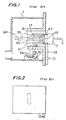
- Fig. 1 shows a gas injection type plasma X-ray source which is disclosed in these papers.
- reference numeral 1 denotes a vacuum vessel; 7, a fast acting puff valve; 13, a capacitor; 17, a gas injection electrode; 18, a mesh electrode; 21, a switch; 26, X-rays produced; 28, an X-ray extraction window of a Be film; 29, an X-ray mask; 30, a wafer; 43, a gas plenum provided in the fast acting puff valve; 45, a piston; 61, a gas jet; 63, a pinched plasma; and 64, a stream or group of charged particles.
- the gas stored in the gas plenum 43 is instantaneously forced into the space between the electrodes 17 and 18 which are in opposed relationship with each other in the vacuum vessel 1 by driving the piston 45 of the fast acting puff valve 7 at a high speed, whereby the gas jet 61 is formed between the electrodes 17 and 18. Thereafter, the switch 21 is closed so that a voltage is applied between the electrodes 17 and 18 from the capacitor 13 which is charged. As a result, the gas jet 61 is ionized by a discharge and is converged by flowing a current, so that a plasma is pinched toward the center. Thus, the high temperature and high density plasma 63 is produced.
- a gas is injected between the electrodes by operating the fast acting gas valve with a high plenum gas pressure, as described above, so that the gas density between the electrodes reaches a high value in the range of 1 ⁇ 10 20 ⁇ 1 ⁇ 10 22 cm -3 .
- the gas density is increased during the discharge caused by the current flowing after the plasma has been pinched. Therefore, a high pressure arc discharge which is one of the characteristics of a discharge at a high gas pressure occurred, so that the electrodes are locally heated.
- the melting of electrodes is accelerated and the electrodes are consumed so that the materials of the electrodes contaminate the inner walls of the vessel.
- high energy electrons and ions and high temperature gases which are produced by the discharge are increased.
- the plasma 63 is produced by the gas jet 61 along the axis of the electrodes as shown in Fig. 1, a large amount of high energy charged particles such as ions and electrons are emitted in the direction of the axis of the plasma 63.
- the X-ray extraction window 28 is located in the direction of the axis of the plasma, it is seriously damaged, so that it is impossible to make an exposure. Therefore, as shown in Fig. 1, the X-ray window 28, the X-ray mask 29 and the wafer 30 are located in the radial direction of the pinched plasma 63 and an exposure is made in vacuum.
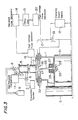
- Fig. 2 shows an X-ray pin-hole picture photographed in the radial direction of the X-ray source through a Be film which is disposed at a position of pattern replication.
- the X-ray source becomes linear so that a viewing angle is increased and a replicated pattern is largely blurred. As a consequence, it is impossible to replicate a fine pattern.
- a conventional gas injection type plasma X-ray source it is only possible to make an exposure in a radial direction of the X-ray source so that the X-ray source is not suitable as an X-ray source for the exposure of a fine pattern.
- One of the objects of the present invention is, therefore, to provide a plasma X-ray source which substantially overcomes the problems encountered in the gas injection type plasma technique with a high X-ray conversion efficiency and which has a wide discharge timing margin, whereby the discharge stability and the X-ray emission reproducibility are enhanced.
- Another object of the present invention is to provide a plasma X-ray source in which continuous discharges are possible at a high repetitive rate and which is capable of replicating a fine pattern.
- a further object of the present invention is to provide an X-ray source which reduces the charged particles produced by a discharge and/or which removes the charged particles thus produced so that X-rays can be obtained in the direction of the axis of the plasma, and so that damage to an X-ray window due to high velocity particles emitted from the plasma is prevented.
- a yet further object of the present invention is to provide an X-ray lithography method for having a high discharge timing margin and replicating a fine pattern by utilizing a plasma X-ray source which has a wide margin of discharge timing, a high degree of discharge stability and an improved X-ray emission reproducibility.
- the inventors discovered phenomena that the discharge was produced in a stable manner and the discharge timing margin becomes rather wider than the prior art even when the plenum gas pressure is less than that of the prior art and the gas rising slope was not so steep as the prior art.
- the present invention is based on the recognition of the phenomena. Also, a new electrode structure was invented in order to to compensate the decrease of the steepness of the gas rising slope by a lowered pressure and to increase the gas conductance of the gas passage. Moreover, the present invention has means for removing the particle beam emitted from the plasma in order to reduce the detrimental effect of the particle beam.
- an X-ray source in which a gas is introduced between a pair of electrodes opposed to each other in a vacuum vessel, so that a gas jet for the production of a plasma is formed, a voltage is applied to perform discharge between the electrodes so that a discharge plasma is produced between the electrodes, and a linear plasma with a high temperature and a high density is produced by the pinch of the plasma due to its own magnetic field produced by the current flowing through the plasma, so that X-rays are emitted from the linear plasma
- the X-ray source comprises means for storing the gas, which is to be introduced between the electrodes, in a gas plenum at a pressure in the range from 20 to 133 kPa (150 Torr to 1000 Torr), and means for injecting the stored gas between the electrodes through a gas valve
- the storing means comprises a gas buffer vessel connected to a gas plenum, a gas pressure sensor for detecting the pressure in the gas plenum, and control
- the gas valve can be a fast acting puff valve and that the gas plenum can be a room formed between a body of the fast acting puff valve and a piston of the fast acting puff valve.
- the gas jet can be in the form of a solid or hollow cylinder.
- one of the pair of electrodes on the side that the X-rays are extracted can be grounded, while a negative potential can be applied to the other electrode.
- One of the pair of electrodes without the center hole can be in the form of a hollow cylinder and can be directly coupled to the gas valve, so that the gas is ejected from the interior of the one electrode and the one electrode may have an inner coaxial cylindrical electrode connected electrically to the one electrode.
- the pair of electrodes may comprise a pair of hollow cylindrical electrodes disposed in coaxial relationship with each other.
- the X-ray source may further comprise a reflector with an X-ray passing hole which is interposed between the pair of electrodes and an X-ray extraction window located below the pair of electrodes along the axis of the pair of electrodes.
- the reflector may have a reflecting plane which is inclined at a predetermined angle relative to the axis of the pair of electrodes.
- the X-ray source may further comprise an evacuation system which is coupled to the vacuum vessel to evacuate the inside of the vacuum vessel and that the reflecting plane is opposed to the evacuation system.
- the reflector may have a plurality of beam reflecting portions which are spaced apart from each other.
- the X-ray source may further comprise a charged particle remover which has an X-ray passing window and is coaxial with the axis of the pair of electrodes.
- the remover can be interposed between the pair of electrodes and a X-ray extraction window located below the pair of electrodes.
- the charged particle remover may have a magnet which is so disposed as to produce a magnetic field for deflecting the incoming charge particles.
- the magnetic field can be produced in the direction perpendicular to the direction of extracting the X-rays.
- the reflecting plane of the reflector can be disposed in the magnetic field.
- the X-ray source may further comprise a magnetic shielding plate which has an X-ray passing window and has a high permeability.
- the magnetic shielding plate may be interposed between the pair of electrodes and the plasma remover.
- an X-ray lithography method in which use is made of an X-ray source according to the present invention.
- a gas jet for the production of a plasma is formed between a pair of electrodes in a vacuum vessel, a voltage is applied to perform discharge between the pair of electrodes so that a discharge plasma is produced between the pair of electrodes, and a linear plasma with a high temperature and a high density is produced by the pinch of the plasma due to its own magnetic field produced by the current flowing through the plasma, so that X-rays are emitted from the linear plasma and derived, and in which a wafer is exposed by the emitted X-rays through an X-ray exposure mask, wherein the maximum gas molecular density of the gas jet is so controlled as not to exceed 10 19 cm- 3 , and the X-rays are derived in the direction of the axis of the linear plasma, and the X-rays expose the X-ray exposure mask and the wafer are so arranged along the axis of the linear plasma
- a pressure of a gas to be injected to form the gas jet is in the range from 20 to 133 kPa (150Torr and 1000 Torr). It is most preferable that a pressure of a gas to be injected to form the gas jet is in the range from 20 to 133 kPa (150 Torr and 500 Torr).
- FIG. 3 shows an embodiment of an X-ray source in accordance with the present invention
- reference numeral 1 denotes a vacuum vessel; 2, an evacuation system for the vacuum vessel 1; 3, an evacuation system for adjusting gas; 4, an evacuation valve for adjusting a gas pressure; 5, a gas buffer vessel; 7, a fast acting puff valve; 8, a gas introducing valve; 9, a vessel containing a gas for discharge; and 10, a gas pressure sensor.
- a gas pressure control unit 11 opens or closes the valves 4 and 8 to control the flow rate of a gas for discharge supplied from the gas vessel 9 to the gas buffer vessel 5 and the flow rate of the gas for discharge evacuated by the evacuation system 3 from the gas buffer vessel, so that the pressure in the gas buffer vessel 5 is controlled.
- the pressure of the gas plenum in the fast acting puff valve which is connected to the gas buffer vessel is controlled by controlling the pressure of the gas buffer vessel.
- Reference numeral 12 designates a charging power supply; 13, a capacitor which is charged by the power supply 12; 14, a standard pulse generator; 15, a delay unit for delaying the signal from the pulse generator 14; 16, a high voltage pulse generator which is controlled by the signal from the standard pulse generator 14 to drive the fast acting puff valve 7; 17, a high-voltage electrode to which a negative potential is applied and which is connected to the fast acting puff valve 7 and which can be made of W-Cu alloy or carbon; 18, a grounding electrode made of a W-Cu alloy or carbon; 20, a high voltage pulse generator which generates a high voltage pulse in response to the signal generated by the standard pulse generator 14 and delayed by the delay unit 15; 21, a discharge switch adopted to respond to the pulse from the high-voltage pulse generator 20 so as to control the discharge timing of the capacitor 13; 22, an insulator for electrically insulating the electrode 17 from the electrode 18; 26, an X-ray emitted from the plasma; 27, a charged particle remover disposed along the path of the X-ray in the vacuum vessel
- the vacuum vessel 1 is evacuated to 13 to 1.3 mPa (10- 4- 10- 5 Torr) by the evacuation system 2. Thereafter, the evacuation system 3 for pressure adjustment is activated and the evacuation valve 4 is opened so that the gas buffer vessel 5 and the fast acting puff valve 7 are evacuated. Next, the gas introduction valve 8 is opened, so that the discharge gas from the discharge gas vessel 9 flows to the gas buffer vessel 5 and the fast acting puff valve 7.
- the pressure control unit 11 closes the gas introducing valve 8.
- the high voltage pulse generator 16 for the fast acting puff valve 7 is activated in response to the signal from the standard signal generator 14, so that the fast acting puff valve 7 is driven.
- the discharge gas is injected into the space between the gas introduction electrode 17 to which is applied a high voltage and the grounding electrode 18 which is disposed in opposed relationship with the gas introduction electrode 17.
- the signal from the signal generator 14 is applied to the high voltage pulse generator 20 through the delay unit 15 which is set to coincide with a time when the discharge gas is injected between the electrodes 17 and 18.
- the discharge switch 21 is actuated, so that a high voltage is applied between the discharge electrodes 17 and 18 which are electrically insulated by the insulators 22.
- discharge occurs when the discharge gas is introduced in synchronism with the application of the high voltage pulse.
- the gas is changed to plasma by the discharge and pinches toward the center of the plasma due to the magnetic field produced by the current flowing through the plasma and the electromagnetic action of the ions and electrons in the plasma. Therefore, a high temperature and high density region is produced along the axis of the electrodes, so that the X-ray 26 is emitted.
- the X-ray 26 emitted from the plasma is extracted through the charged particle remover 27 disposed in the direction of the axis of the plasma and the X-ray extraction window 28 consisting of a Be thin film extended over the opening of the vacuum vessel 1, so that the pattern of the X-ray mask 29 disposed in the atmosphere is replicated on the wafer 30 coated with resist.
- the alignment between the X-ray mask 29 and the wafer 30 is attained by the aligner 31.
- the gas pressure sensor 10 detects the pressure variation in the gas buffer vessel 5 when the discharge gas is introduced through the fast acting puff valve 7. In response to the signal from the gas pressure sensor 10 the control unit 11 opens or closes the evacuation valve 4 and the gas introducing valve 8 in such a ,way that the pressure variation may be compensated. As a result, the pressure in the gas buffer vessel is maintained at a predetermined pressure of the order of 20 to 133 kPa (150-1000 Torr).
- the pressure of the puff which is introduced through the fast acting puff valve 7 can be always set at a predetermined pressure.
- a gas jet with the least gas diffusion is produced steeply.
- the pressure of the injected gas is high, the pressure of the gas between the electrodes is increasing rapidly even after the pinch of the plasma is terminated. Therefore, the discharge in the high pressure gas is maintained by the damping oscillation current which flows after the pinch.
- the gas is injected after the gas pressure of the plenum to be injected is controlled at a predetermined pressure level (for instance, 20 to 133 kPa (150-1000 Torr)) by the pressure control unit 11, so that it is possible to control the pressure at which the pressure between the electrodes becomes maximum to an optimum discharge pressure (a few Torr--100 Torr).
- a predetermined pressure level for instance, 20 to 133 kPa (150-1000 Torr)
- the gas pressure between the electrodes is maintained at a pressure in the range of 20 to 40 kPa (150-300 Torr) and the gas density between the electrodes reaches loll cm- 3 at most, so that the current is prevented from being concentrated locally and consequently the electrodes are prevented from being melted.
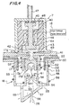
- Fig. 4 shows the construction of the electrodes 17 and 18 fabricated in view of the above- described consideration together with the construction of the fast acting puff valve 7.
- the vacuum vessel 1 is provided with a high voltage input flange 41 which serves as a top wall and a current passage.
- the input flange 41 is provided with a gas ejection nozzle 42.
- a molded insulator 44 of nylon or the like is disposed above the gas ejection nozzle 42 to define a gas plenum 43.
- the insualtor 44 has a hole 40 through which a piston 45 is extended so that the piston 45 reciprocates in the gas plenum 43.
- a solenoid coil 46 for moving the piston 45 vertically is embedded in the insulator 44.
- the piston 45 can be made of a light metal such as aluminum or duralumin which generates a current in response to the change of the magnetic line of force of the coil 46.
- a pulse voltage is applied to the solenoid coil 46 from the high voltage pulse generator 16 so that the piston 45 is immediately lifted.
- a buffer 48 for stopping the piston 45 is attached to the bottom surface of the top plate of the fast acting puff valve 7.
- the buffer 48 has an opening in communication with a passage 47 which in turn is communicated with the gas buffer vessel 5.
- the top of the piston 45 is engageable with the buffer 48.
- the flange 41 is provided with a sealing member 49 such as an O-ring adapted to engage with the bottom surface of the piston 45 so as to vacuum-seal the gas plenum 43.
- the discharge gas which flows through the passage 47 is introduced into the gas plenum 43 when the piston 45 is moving downward.
- the piston 45 is moved upward rapidly in response to the application of the high voltage pulse from the pulse generator 16 to the solenoid coil 46, the discharge gas flows downward through the gas ejection nozzle 42.
- the piston 45 moves downward by its own weight and the vacuum in the vacuum vessel 1, so that the discharge gas is introduced into the gas plenum 43 again through the passage 47.
- a grounded flange 50 which forms a current return circuit is disposed via the insulator 22 below the flange 41 and is grounded.
- the electrode 17 having double cylinders is disposed below the flange 41.
- the flange 41 has an opening 17E which is communicated with the gas ejection nozzle 42 of the flange 41.
- a gas introduction passage 51 is defined between the outer wall 17A and the inner wall 17B of the electrode 17.
- the outer wall 17A and the inner wall 17B of the electrode 17 are joined integrally by a ring 17C.
- the opening 17E and the gas introduction passage 51 are communicated with each other through a plurality of openings 17D which are spacedly arranged on the circumference of the ring 17C.
- a cooling water pipe 52 for cooling the electrode 17 is disposed around the electrode 17.
- a cylinder 53 is extended downwardly from the undersurface of the flange 50.
- An inner cylinder 54 is extended upwardly and spaced apart from the bottom surface of the cylinder 53 by a suitable distance.
- the lower cylinder 54 forms the electrode 18 which is grounded.
- the annular upper end of the grounded electrode 18 is substantially in opposed relationship with the gas introduction passage 51.
- the grounded electrode 18 may have a plurality of gas evacuating openings 55 on the circumferential surface of the electrode 18.
- Cooling water pipes 56 are disposed on the surface of the grounded electrode 18.
- a beam reflector 57 is disposed below the grounded electrode 18 in an inclined manner so as to cover the cylinder 54.
- the beam reflector 57 has at least one inclined reflecting plate having an X-ray extraction window 58 in coaxial relationship with the electrodes 17 and 18.
- a charged particle evacuating port 59 is provided at the end of the beam reflector 57 so that the charged particles reflected by the beam reflector 57 pass through the evacuating port 59.
- reference numeral 61 denotes a gas jet ejected from the gas introduction passage 51; 62, a current flowing between the electrodes 17 and 18; 63, a plasma pinched in the directions indicated by the arrows; and 64, the loci of the charged particles emitted from the plasma 63.
- the gas in the gas plenum 43 forms the gas jet 61 in the form of a hollow cylinder through the gas introduction passage 51 of the electrode 17 between the electrode 17 and the grounded hollow cylindrical electrode 18.
- the diameter of the gas ejection nozzle 42 is determined to be 10 mm or more and the gas introduction passage 51 is diverged downwardly so that the Mach number of the gas ejected from the gas introduction passage 51 is increased.
- the current 62 which flows in the pinched plasma is ejected from the inner wall of the cylindrical cavity 17B which extends along the axis of the electrode 17 and the inner wall of the grounded electrode 18; that is, the hollow cylinder 54.
- the current which flows to the electrodes 17 and 18 when the plasma is pinched is supplied from the whole inner surfaces of the electrodes 17 and 18, so that the current is prevented from flowing locally in the electrodes.
- the electrodes are prevented from being heated and melted due to the localized current flow and the electrode consumption due to the discharge is minimized.
- Even after 1000 times of discharges only small portions of the inner wall surfaces of the electrodes 17 and 18 are consumed. That is, electrode consumption is substantially eliminated.
- the electrodes as shown in Fig. 4 when they are made of C or W-Cu, continuous discharges more than 10 5 times is possible.
- the grounded electrode 18 which is in opposed relationship with the electrode 17 is hollow, there is the decreased possibility that the gas ejected from the fast acting puff valve 7 is reflected by the grounded electrode 18, so that the gas jet 61 is produced with a high degree of reproducibility in a very stable manner.
- the plasma is pinched with a high degree of reproducibility in a stable manner; electrode consumption is minimized; and X-ray is emitted from the plasma in a stable manner.
- the shape of the opening of the electrode 18 for extracting the X-ray is not limited to circle and any shape can be employed.
- Fig. 6 shows an embodiment of the upper electrode 17 in Fig. 4.
- the electrode 17 has the cylindrical outer electrode 17A and the hollow cylindrical inner electrode 17B which is disposed within the outer electrode 17A in coaxial relationship therewith and is electrically connected thereto.
- the inner electrode 17B has a plurality (for example, eight) of openings 17D formed through the side wall of the inner electrode 17B and circumferentially spaced apart from each other. The gas flows into the gas introduction groove 51 between the outer wall of the inner electrode 17B and the inner wall of the outer electrode 17A through these openings 17D.
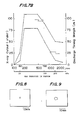
- Fig. 7A shows illustrated experimental results of the relationship between the X-ray output obtained from the X-ray source of the present invention as shown in Fig. 3 and the discharge timing (that is, the time set by the delay unit 15 shown in Fig. 3).
- the X-ray output (J/shot) emitted by one discharge is plotted along the ordinate and the discharge timing (us) along the abscissa.
- the white circles show the results of the experiments in which the discharges were produced after the pressure of the gas plenum is set at a low gas pressure (40 kPa or 300 Torr or 0.4 atm.) and the gas is injected in accordance with the present invention, while the black dots show the experimental results when a gas was injected at a high pressure as shown in Fig.
- the high pressure was 307 kPa (2300 Torr (3 atm.)).
- the discharge energy was 3 kJ in both cases.
- the same discharge circuit was used.
- the allowance of the discharge timing that the plasma is pinched and discharged is 10 ps between the timings of 390 ⁇ s ⁇ 400 us.
- the gas is injected rapidly at a high flow rate so that the gas pressure between the electrodes 17 and 18 rises rapidly withina few microsends, because of the fact that the timing interval is 10 ⁇ s.
- the gas is injected at a pressure within a range of 20 to 133 kPa (150-1000 Torr) and the hollow cylindrical electrodes are used.
- the plasma is pinched with a wider margin of a discharge timing of about 100 us between the timings of 400 ⁇ s and 500 us. This allowance is ten times as wide as the discharge timing margin of 10 ps in a conventional method.
- the gas pressure between the discharge electrodes is maintained at an optimum level for a long time of about 100 us and that even if the injected gas jet is diffused and collapsed after the elapse of a long time longer than 50 ps since the gas is injected between the electrodes 17 and 18, the stable annular initial discharge is produced, so that the plasma is pinched.
- the pulse width of the injected gas 17 and 18 is of the order of 100 ⁇ s, so that the gas pressure between the electrodes 17 and 18 is always maintained at an optimum level at which the plasma is pinched and does not increase to a high pressure.
- the X-ray output is increased higher by two or three times than the X-ray output obtained by a conventional method.
- the hollow cylindrical electrode 18 is used in the present invention, so that the length of the pinched plasma is not limited and accordingly a long pinched plasma is established. Consequently, an inductance of the plasma is increased, so that the electric energy stored in the capacitor is effectively injected into the plasma.
- Another reason is that the current flowing through the plasma is supplied from the inner walls of the electrodes, so that the current is prevented from being localized and the pinched plasma exists in a stable manner for a long time. It was recognized that the X-ray was emitted from the plasma during a long time of 2 ps when the plasma was pinched for a plurality of times and that the life of the pinched plasma was long.
- Fig. 7B shows the relationship between the X-ray output and the gas pressure of the plenum and the relationship between the discharge timing margin and the gas pressure of the plenum. It is seen that the X-ray output as well as the discharge timing margin are high when the pressure is equal to or lower than 1000 Torr (1.31 atm.) and especially lower than 0.1 MPa (760 Torr (1 atm.)). When the gas pressure of the plenum is decreased to 67 kPa (500 Torr) or less, both the X-ray output and the discharge timing margin are saturated. The lower limit of the plenum gas pressure for the X-ray output and the discharge timing margin was 20 kPa (150 Torr).
- the speed of the gas ejected from the path 51 of the electrode 17 mainly depends upon a pressure of the injected as (i.e., a pressure in the gas plenum 43), a shape of the electrode 17, types of gas to be injected, and so on.
- the following table shows examples of the speed in case of Ne gas.
- the present invention by decreasing the gas pressure in the plenum lower than the pressure used in a conventional method, stability and reproducibility of discharges are improved and the X-ray output is increased.
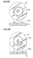
- Fig. 8 shows the picture of the position of the pinched plasma when a discharge was produced in the plasma X-ray source of the present invention at a gas pressure in the range of 20 to 133 kPa (150-1000 Torr) and an X-ray pin-hole camera was located along the axis of the electrodes 17 and 18. The resultant picture was obtained by 20 times of exposures in one picture. It is seen that the X-ray emitting region is as narrow as 2 mm in diameter. This means that the positions of pinched plasmas are stabilized.
- Fig. 9 shows the picture of the positions of pinched plasmas taken under the same conditions as described above except that the gas was injected at a high pressure according to a conventional method. It is seen that the range of the positions of pinched plasmas is 5 mm in diameter. That is, the positions of pinched plasmas vary over a wide range as compared with those in Fig. 8. Thus, according to the present invention, the position at which a plasma is pinched is substantially stabilized.
- the experiments show clearly that according to the present invention the X-ray emission efficiency is improved and the position of a pinched plasma is stabilized. It is known that in case of a proximity X-ray exposure method, the smaller the diameter of an X-ray source, the more sharply a pattern is replicated. It is seen from the picture shown in Fig. 8 that it is advantageous to perform exposure in the direction of the axis of the electrodes. In this case, it becomes necessary to protect the X-ray extraction window from the charged particles emitted from the plasma.
- the charged particles are mostly emitted in the direction of the axis of the pinched plasma column. Therefore, according to the present invention, as shown in Fig. 4, there is provided the beam reflector 57 in the direction of the axis of the electrodes 17 and 18.
- the beam reflector 57 has the reflecting plate in which the X-ray extraction window 58 is opened.
- the reflecting plate is inclined at a predetermined angle relative to the axis of the grounded electrode 18 so that the reflecting plate is directed toward the evacuation system 2 in Fig. 3.
- the plasma 63 produced between the electrodes 17 and 18 is injected toward the X-ray extraction window 28 (see Fig. 3) coaxial with the electrodes 17 and 18, the plasma 63 strikes against the reflecting plate of the beam reflector 57 and accordingly has a momentum in a direction different from the injection direction of the plasma 63. As a result, the plasma travelling toward the X-ray extraction window 28 is decreased. Furthermore, the plasma which is directed from the electrodes 17 and 18 toward the X-ray extraction window 58 collides against the plasma reflected from the beam reflector 57, so that the plasma has a momentum component in the direction perpendicular to the axis of the electrodes 17 and 18.
- the reflecting plate of the beam reflector 57 may have a flat, curved or conical reflecting surface.
- Figs. 10 and 11 show amounts of the charged particles emitted by the discharges in the apparatus shown in Fig. 4 without the provision the charged particle remover 27 and the beam reflector 57.
- Ne gas was used to produce a discharge.
- the capacity of the capacitor 11 was 3 pF.
- the charging voltage was 50 kV.
- a Faraday cup was placed at the position spaced by 25 cm away from the electrode 18 in the direction of the axis of the electrodes 17 and 18 and a resistor of 2 ohms was connected between the Faraday cup and the ground, so that a voltage across this resistor was measured.
- Fig. 10 shows the result obtained when the pressure of the injected Ne gas was 2 atm. It is seen that a negative voltage higher than 300 V was detected. This means that a large amount of electrons are emitted in the direction of the axis of the electrodes 17 and 18.
- Fig. 11 shows the result obtained when the pressure of Ne gas was maintained at a low pressure of 40 kPa (0.4 atm. or 300 Torr) by the pressure control unit 11. It is seen that a negative potential was generated at the same time in Fig. 10. The voltage was of the order of 70 V which was less than one quarter of the voltage shown in Fig. 10. As described above, when the pressure of the injected gas is decreased, the amount of charged particles emitted from the plasma between the electrodes in response to the discharge is decreased.
- the plasma pinch time (that is, the period of time from the time that a discharge is started to the time that the plasma is pinched) is of the order of 600 ns in either case and it is considered that the gas densities between the electrodes when the discharge is started are substantially the same in both cases of Figs. 10 and 11.
- the gas pressure between the electrodes is rapidly increased and maintained at a high pressure after the pinch.
- a large amount of gas is ionized, so that a large amount of charged particles are emitted as shown in Fig. 10.
- an X-ray extraction window 28 in the direction of the axis of the electrodes 17 and 18. Furthermore, it is also possible to maintain vacuum by means of the X-ray extraction window 28, because the X-ray extraction window 28 is hardly damaged. As a result, the diameter of the X-ray source as viewed from the wafer to be exposed becomes 2 mm which is substantially equal to the diameter of the pinched plasma, so that a pattern to be replicated is more sharply focussed. Moreover, it is possible to extract the X-ray through the X-ray extraction window into the surrounding atmosphere, so that the exposure in the atmosphere is available. As a result, the thermal diffusion of an X-ray mask becomes faster, so that the X-ray mask is not subjected to thermal expansion and that a fine pattern is replicated with a higher degree of accuracy.
- the evacuation system can be made compact in size.
- the aligner can be simplified in construction. It is also possible in a simple manner to dispose the plasma X-ray generator below the wafer and the mask aligner.
- the discharge gas is injected at a pressure in the range of 20 to 133 kPa (150-1000 Torr), so that the injected gas can be evacuated at a high speed.
- a plasma X-ray source in which the discharge can be performed continuously at a high repetitive rate of a few Hz.
- the diameter of the X-ray source is small and the X-ray output is high, so that there is provided a plasma X-ray source for replicating a fine pattern at a high yield.
- a strong X-ray is emitted within a short period of time, so that the present invention can be utilized in X-ray annealing, CVD, etching and so on.
- the present invention can be utilized as an X-ray source for analyzing high speed phenomenon, for various analysis and for medical and industrial purposes.
- the beam reflector 57 is disposed on the side of the grounded electrode 18 and the charged particle remover 27 is disposed under the vacuum vessel 1 separately from the charged particle remover 27. Therefore, the charged particles which are not reflected by the beam reflector 57 and pass through the X-ray extraction window 58 are trapped by the charged particle remover 27.
- a beam reflector and a charged particle remover are constructed as an integral structure.
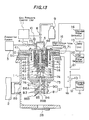
- the portions corresponding to those in Figs. 3 and 4 are denoted by the same reference numerals.
- the high voltage input flange 41 has an opening 71 which accommodates the fast acting puff valve 7 and which is closed by a flange 72 for holding the valve 7 in position.
- the flange 72 also has an opening 73 which is communicated with the gas buffer vessel 5.
- the fast acting puff valve 7 is extended downwardly from the flange 72.
- the electrode 18 is in the form of a cylinder in which both the fast acting puff valve 7 and the electrode 17 are housed.
- An electrode 74 is disposed at the bottom of the cylindrical electrode 18 in opposed relationship with the electrode 17.
- a magnetic shielding plate 75 is also attached to the bottom of the cylindrical electrode 18.
- An X-ray extraction hole 76 is opened through the electrode plate 74, the bottom plate of the cylindrical electrode 18 and the magnetic shielding plate 75.
- the charged particle remover 27 as shown in Fig. 14 is attached to the magnetic shielding plate 75.
- the charged particle remover 27 has a yoke 81 for establishing a magnetic circuit, permanent magnets or electromagnets 82 and 83 which are attached to the opposed legs 81A and 81 B of the yoke 81 so as to deflect the charged particles, and protective plates 84 and 85 for the respective magnets 82 and 83.
- a beam reflector plate 86 is disposed in an inclined manner between the protective plates 84 and 85. The upper end of the beam reflector plate 86 is securely joined to a supporting member 87 which in turn is securely joined to the yoke 81.
- the magnets 82 and 83 are so disposed that the N pole of one magnet is in opposed relationship with the S pole of the other magnet and that the strength of the magnetic field between the magnets 82 and 83 is maximum by the arrangement of the yoke 81.
- Only one beam reflector plate 86 may be used, but in this embodiment, two beam reflector plates 86A and 86B are provided as shown in Fig. 13.
- the beam reflector 86A has an X-ray extraction window 88A while the beam reflector 86B has an X-ray extraction hole 88B.
- the upper X-ray extraction hole 88A is smaller in size than the lower X-ray extraction hole 88B.
- These particle beam reflectors 86A and 86B are so inclined that the charged particles reflected by the beam reflectors 86A and 86B are directed toward the evacuation system 2.
- a charged particle absorbing mesh 89 is disposed at the inlet of the evacuation system 2.
- reference numeral 90 denotes one example of the loci of the electrons emitted from the plasma 63; 91, one example of the loci of the ions; and 93, one example of the loci of the neutral particles.
- the vacuum vessel 1 is exhausted to 13 to 1.3 mPa (10-°-10- 5 Torr) by the evacuation system 2. Thereafter, the evacuation system 3 for pressure regulation is activated to open the evacuation valve 4, so that the gas buffer vessel 5 and the fast acting puff valve 7 are evacuated. Next, the gas introduction valve 8 is opened, so that the discharge gas from the gas vessel 9 flows into the gas buffer vessel 5 and the fast acting puff valve 7. After the pressure sensor 10 has detected that a predetermined pressure has been reached, the gas pressure control unit 11 closes the gas introduction valve 8.
- the charging power supply 12 charges the capacitor 13 and in response to the signal from the standard pulse generator 14, the high voltage pulse generator 16 for the fast acting puff valve 7 is activated, so that a magnetic field is produced in the driving coil 46 which is molded with the insulator 44 such as nylon.
- the piston 45 is moved upwardly by the electromagnetic repulsion force produced between the piston 45 and the driving coil 46.
- the discharge gas which has been filled in the gas plenum 43 at a predetermined pressure by means of the gas pressure control unit 11 flows through the space between the piston 45 and the vacuum seal 0-ring 49 and then through the gas injection nozzle 42 to the openings 17E.
- the upward movement of the piston 45 is stopped when the piston 45 strikes against the buffer 48 attached to the flange 72 which in turn is securely joined to the high voltage input flange 41 with bolts. Thereafter, the piston 45 moves downward by its own weight and the difference of the pressure in the vacuum vessel 1 and the gas plenum 43. While the piston 45 is made into contact with the buffer 48, the gas port 73 of the fast acting puff valve 7 is closed by the piston 45. Simultaneously, the cylindrical wall surface of the piston 45 closes the end of the gas introduction groove 40, so that no gas flows into the gas plenum 43.
- the high velocity gas flows pass through the gas openings 17E and the nozzle 51 defined between the outer electrode 17A and the inner electrode 17B into the space defined between the opposed electrodes 17 and 74 and the gas jet is formed between the electrodes 17 and 74.
- the signal from the signal generator 14 is applied to the high voltage pulse generator 20 through the delay unit 15 which is set at a delayed time that the gas reaches the electrode 74.
- the discharge switch 21 is actuated.
- the charged particle remover 27 is disposed in the direction of the axis of the plasma 63. Since the Rama radius is small because of the magnetic fields of magnets, an electron emitted from the plasma 63 travels along the locus 90 and is trapped by the charged particle remover 27. Ions have a large mass, so that the Rama radius is greater. As a result, the ion is slightly deflected as indicated by the locus 91 by the magnetic field and is deflected again by the beam reflector 86.
- the ion which is reflected from the beam reflector 86 is absorbed by a charged particle absorbing mesh 89 before it enters the evacuation system 2 and flows into the ground. Therefore, no current flows through the evacuation system 2.
- the neutral particles 82 emitted from the plasma are reflected by the beam reflector 86 toward the evacuation system 2 and are discharged into the surrounding atmosphere by the evacuation system 2.
- the vacuum vessel 1 has the X-ray extraction window 28 coaxial with the plasma, so that the X-ray is emitted into the exterior of the vacuum vessel 1.
- the pressure variation in the gas buffer vessel 5 is detected by the pressure sensor 10 when the gas is injected between the electrodes 17 and 18 by the fast acting puff valve 7 and in response to the signal from the gas pressure sensor 10, the pressure control unit 11 opens or closes the evacuation valve 4 and the gas introduction valve 8, thereby compensating the pressure variation.
- the pressure in the gas buffer vessel 5 as well as the pressure in the gas plenum 43 are maintained at a predetermined gas pressure level of the order of 20 to 133 kPa (150-1000 Torr).
- Fig. 15 shows the relationship between the pressure of the injected gas; that is, the pressure in the gas buffer 5 and the gas plenum 43 and the amount of charge (negative charge or electrons) detected when the capacitor 21 of 3 pF was charged to 50 kV and the Ne gas was introduced into the apparatus shown in Fig. 13 and discharged without the charged particle remover 27 and a Faraday cup was located at the X-ray extraction window 28.
- the Faraday cup output (750 V) with the pressure of the injected gas of 0.1 MPa (760 Torr (1 atm.)) is normalized as 1.0. It is seen that the lower the gas pressure in the plenum the smaller the amount of charge becomes.
- the charge amount is reduced to about 10% of the charge amount obtained when the gas is injected at a pressure of 0.1 MPa (760 Torr).
- an amount of charge particles (electrons) emitted from the plasma are remarkably reduced.
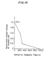
- Fig. 16 shows the results obtained when only the effect of the deflection magnetic field was measured while the beam reflector 86 of the charged particle remover 27 was not provided. More particularly, Fig. 16 shows the relationship between the strength of the deflection magnetic field and the Faraday cup output voltage when the discharge was produced with the pressure of the injected gas being set at 40 kPa (300 Torr). The Faraday cup output is normalized as 1.0 when the strength of the magnetic field is zero. The detected charge (negative charge; that is, electrons) is remarkably reduced at the magnetic field of the order of 400 G and is completely eliminated at 1 kG.
- the beam reflector 86 as shown in Fig. 13 is provided so as to deflect such neutral particles.
- the electrons which come downwardly from the charged particle remover 27 are deflected toward the beam deflector supporting member 86 (see Fig. 13) by the magnetic field produced by the magnets 82 and 83. After all, they impinge against the beam reflector 86 or the magnet protection plates 84 and 85, so that a current flows.
- the direction of the momentum obtained when an ion impinges against the beam reflector 86 is the same as the direction of the electromagnetic force exerted to the ions due to the magnetic field produced by the ions and the magnets 82 and 83, so that even a heavy ion is deflected because of the synergistic effect of the beam reflector 86 and the magnets 82 and 83. Furthermore, high velocity neutral particles such as high temperature gases are also reflected by the beam reflector 86, so that the directions of their momentum change and the neutral particles are deflected.
- the charged particle remover 27 as shown in Fig. 14 is interposed between the X-ray extraction window 28 and the electrodes 17 and 18 which produce a plasma, it is preferable that the charged particle remover 27 is disposed as closely as possible to the plasma, so that the ions which are hardly deflected will not reach the X-ray extraction window 28. Therefore, in the embodiment as shown in Fig. 13, the charged particle remover 27 is directly mounted on the electrode 18. In this case, the stable emission of the X-ray from the plasma is adversely affected by the influence of the leakage magnetic fields from the deflection magnets 82 and 83 upon the convergence and pinching of the plasma.
- the shielding plate 75 which can be made of a material (such as soft iron) with a high permeability and has the X-ray extraction window 76 is interposed between the charged particle remover 27 and the grounded electrode 18.
- the stable X-ray emission is ensured without being adversely influenced by the leakage magnetic fields of the deflection magnets 82 and 83.
- the X-ray extraction window is prevented from being damaged by the plasma and the highly bright X-ray is extracted through the X-ray extraction window in a stable manner. Since the X-ray extraction window is not damaged, vacuum in the vacuum vessel 1 can be maintained by the X-ray extraction window, so that the X-ray can be emitted into the atmosphere. As a result, the exposure in the atmosphere can be realized.
- the thermal diffusion of the X-ray mask is facilitated, so that the X-ray mask is prevented from being thermally distorted and a fine pattern can be replicated at a high speed in a stable manner with a high degree of accuracy.
- the X-ray source in accordance with the present invention can be utilized for the X-ray analysis of high speed phenomenon, other various analyses and medical and industrial purposes.
- an X-ray source in accordance with the present invention can be utilized in various processes for the fabrication of LSI such as an optical CVD process, an etching process, an annealing process and so on.
Description
- The present invention relates to a plasma X-ray source for generating high output and highly stable soft X-rays to be used in an exposure apparatus for replicating a fine pattern to be used in the fabrication of semiconductor integrated circuits and an X-ray lithography method utilizing the X-ray source.
- One of the lithography processes which play a very important role in the fabrication of integrated circuits is an X-ray lithography. So far an electron beam impact source in which X-rays are generated by the bombardment of an electron beam against a target consisting of Al, Cu, Mo, Si, Pd or the like has been used as a soft X-ray source of an X-ray exposure apparatus. However, this source has a problem that the X-ray generating efficiency is as low as 0.01% so that high output X-rays cannot be obtained and consequently the pattern replication yield is low.
- On the other hand, a plasma X-ray source utilizing a high density plasma has a high X-ray generating efficiency, so that it is expected that high output X-rays are obtained. An efficiency of the conversion of the energy applied to a plasma X-ray source into soft X-rays is higher than 1%,so that a high efficiency hundred times as high as the efficiency of an electron beam impact X-ray source is expected.
- In the case of a plasma X-ray source, a plasma is produced by a discharge. A large current of the order of hundreds kA flows through the plasma so that the plasma is caused to pinch by its own magnetic field produced by the current and the electromagnetic action of the plasma to produce a high temperature and high density plasma. X-rays are emitted from the high temperature and high density plasma. Since the plasma is produced by flowing a large current as described above, there arise the problems of stability in X-ray intensity, electrode consumption and damage to an X-ray extraction window by a plasma. As a result, it is extremely difficult in practice to use the plasma X-ray source as an X-ray exposure source.
- A gas injection type plasma X-ray source which is one of the plasma X-ray sources is disclosed in the following paper: ,
- (1) "X-ray lithography using a pulsed plasma source", Pearlman et al., J. Vac. Sci. Technol., 19(4), Nov./Dec. 1981, pp. 1190-1193;
- (2) "Evaluation of the gas puff Z pinch as an X-ray lithography and microscopy source", J. Bailey et al., Appl. Phys. Lett. 40(1), 1 January 1982, pp. 33-35; and
- (3) "Imploding argon plasma experiments", C. Stallings et al., Appl. Phys. Lett. 35(7), 1979, pp. 524-526; In Review of Scientic Instruments, Vol. 49, No. 6, June 1978, pages 872 to 873, A. Fisher et al.: "Fast valve for gas injection into vacuum", a magnetically driven gas valve for use in plasma experiments is used where the filling pressure of the valve is less than 133 kPa.
- Fig. 1 shows a gas injection type plasma X-ray source which is disclosed in these papers. In Fig. 1,
reference numeral 1 denotes a vacuum vessel; 7, a fast acting puff valve; 13, a capacitor; 17, a gas injection electrode; 18, a mesh electrode; 21, a switch; 26, X-rays produced; 28, an X-ray extraction window of a Be film; 29, an X-ray mask; 30, a wafer; 43, a gas plenum provided in the fast acting puff valve; 45, a piston; 61, a gas jet; 63, a pinched plasma; and 64, a stream or group of charged particles. In a gas injection discharge method, the gas stored in thegas plenum 43 is instantaneously forced into the space between theelectrodes vacuum vessel 1 by driving thepiston 45 of the fast acting puff valve 7 at a high speed, whereby thegas jet 61 is formed between theelectrodes switch 21 is closed so that a voltage is applied between theelectrodes capacitor 13 which is charged. As a result, thegas jet 61 is ionized by a discharge and is converged by flowing a current, so that a plasma is pinched toward the center. Thus, the high temperature andhigh density plasma 63 is produced. - In the gas injection discharge method, it is necessary that the rising slope of the injected gas is formed as steeply as possible, so that when the gas jet is formed between the electrodes, it has a gas density adapted to cause a discharge before the gas jet is diffused. The time variation in a flow rate Q of the gas which flows when the
piston 40 of the fast acting puff valve is opened is expressed by the following equation:
- Po: the gas pressure of the plenum in the fast acting puff valve 7;
- D: conductance of the passage through which the gas flows; and
- I: distance of the gas passage.
- The above equation shows that in order to obtain a steep gas profile by increasing the volume of the flowing gas as possible, the high gas pressure Po is adopted usually. Therefore, in the prior art, so far the fast acting puff valve usually introduces the gas at such a high pressure of about 0.5 MPa (5 atm) so that the gas injection velocity is increased.
- Meanwhile, in the prior art, a gas is injected between the electrodes by operating the fast acting gas valve with a high plenum gas pressure, as described above, so that the gas density between the electrodes reaches a high value in the range of 1×10²⁰―1×1022 cm-3. Moreover, it takes about 0.1 ms to open or close the fast acting puff valve. Therefore, the gas density between the electrodes is increased after the gas jet is formed and discharged between the electrodes, and then the
plasma 44 is pinched. As a result, the gas density is increased during the discharge caused by the current flowing after the plasma has been pinched. Therefore, a high pressure arc discharge which is one of the characteristics of a discharge at a high gas pressure occurred, so that the electrodes are locally heated. As a consequence, the melting of electrodes is accelerated and the electrodes are consumed so that the materials of the electrodes contaminate the inner walls of the vessel. Furthermore, high energy electrons and ions and high temperature gases which are produced by the discharge are increased. - When such a high temperature and high density plasma is used as an X-ray exposure source, electrode consumption degrades discharge reproducibility and the stability of X-ray emission. Furthermore, the breakdown voltage of an insulator is decreased because of the adhesion of electrode materials to the surfaces of the insulator to which a high voltage is applied. When the plasma X-ray source is used as an X-ray exposure source, the transmissivity of X-rays through the
X-ray extraction window 28 is decreased because of the deposition of the electrode materials to the X-ray window. As a result, the continuous X-ray exposure is impossible. Moreover, because the gas density between the electrodes reaches a high value, the high energy charged particles and high temperature gases impinge against the X-ray extraction window, so that theX-ray extraction window 28 is damaged. - Especially, when the
plasma 63 is produced by thegas jet 61 along the axis of the electrodes as shown in Fig. 1, a large amount of high energy charged particles such as ions and electrons are emitted in the direction of the axis of theplasma 63. As a result, even when theX-ray extraction window 28 is located in the direction of the axis of the plasma, it is seriously damaged, so that it is impossible to make an exposure. Therefore, as shown in Fig. 1, theX-ray window 28, theX-ray mask 29 and thewafer 30 are located in the radial direction of the pinchedplasma 63 and an exposure is made in vacuum. - Fig. 2 shows an X-ray pin-hole picture photographed in the radial direction of the X-ray source through a Be film which is disposed at a position of pattern replication. When a proximity exposure method is employed, the X-ray source becomes linear so that a viewing angle is increased and a replicated pattern is largely blurred. As a consequence, it is impossible to replicate a fine pattern. In view of this, when a conventional gas injection type plasma X-ray source is used, it is only possible to make an exposure in a radial direction of the X-ray source so that the X-ray source is not suitable as an X-ray source for the exposure of a fine pattern.
- In addition, when a gas is injected at a high pressure, a large volume of gas is introduced, so that it takes a long time to exhaust the gas in the vacuum vessel. As a result, in the gas injection type X-ray source, it is impossible to repeat discharges at a high repetitive rate.
- Furthermore, when an X-ray source is used for exposure, it is necessary that the charged particles which impinge against an X-ray extraction window must be reduced as much as possible. So far, no satisfactory method has been proposed to overcome this problem.
- One of the objects of the present invention is, therefore, to provide a plasma X-ray source which substantially overcomes the problems encountered in the gas injection type plasma technique with a high X-ray conversion efficiency and which has a wide discharge timing margin, whereby the discharge stability and the X-ray emission reproducibility are enhanced.
- Another object of the present invention is to provide a plasma X-ray source in which continuous discharges are possible at a high repetitive rate and which is capable of replicating a fine pattern.
- A further object of the present invention is to provide an X-ray source which reduces the charged particles produced by a discharge and/or which removes the charged particles thus produced so that X-rays can be obtained in the direction of the axis of the plasma, and so that damage to an X-ray window due to high velocity particles emitted from the plasma is prevented.
- A yet further object of the present invention is to provide an X-ray lithography method for having a high discharge timing margin and replicating a fine pattern by utilizing a plasma X-ray source which has a wide margin of discharge timing, a high degree of discharge stability and an improved X-ray emission reproducibility.
- The inventors discovered phenomena that the discharge was produced in a stable manner and the discharge timing margin becomes rather wider than the prior art even when the plenum gas pressure is less than that of the prior art and the gas rising slope was not so steep as the prior art. The present invention is based on the recognition of the phenomena. Also, a new electrode structure was invented in order to to compensate the decrease of the steepness of the gas rising slope by a lowered pressure and to increase the gas conductance of the gas passage. Moreover, the present invention has means for removing the particle beam emitted from the plasma in order to reduce the detrimental effect of the particle beam.
- In a first aspect of the present invention, there is provided an X-ray source in which a gas is introduced between a pair of electrodes opposed to each other in a vacuum vessel, so that a gas jet for the production of a plasma is formed, a voltage is applied to perform discharge between the electrodes so that a discharge plasma is produced between the electrodes, and a linear plasma with a high temperature and a high density is produced by the pinch of the plasma due to its own magnetic field produced by the current flowing through the plasma, so that X-rays are emitted from the linear plasma, characterized in that the X-ray source comprises means for storing the gas, which is to be introduced between the electrodes, in a gas plenum at a pressure in the range from 20 to 133 kPa (150 Torr to 1000 Torr), and means for injecting the stored gas between the electrodes through a gas valve, that the storing means comprises a gas buffer vessel connected to a gas plenum, a gas pressure sensor for detecting the pressure in the gas plenum, and control means receiving a pressure signal from the gas pressure sensor for supplying control signals to an entrance valve and an exit valve of the gas buffer vessel, that the control means controls the pressure in the gas plenum is so controlled that the maximum gas molecular density of the gas jet does not exceed 1019 cm-3, and that the pair of electrodes are opposed to each other substantially in coaxial relationship and at least one of the pair of electrodes may have a center hole, so that X-rays are extracted in the direction of the axis of the linear plasma produced substantially along the axis of the pair of electrodes.
- The gas valve can be a fast acting puff valve and that the gas plenum can be a room formed between a body of the fast acting puff valve and a piston of the fast acting puff valve. The gas jet can be in the form of a solid or hollow cylinder.
- Here, one of the pair of electrodes on the side that the X-rays are extracted can be grounded, while a negative potential can be applied to the other electrode. One of the pair of electrodes without the center hole can be in the form of a hollow cylinder and can be directly coupled to the gas valve, so that the gas is ejected from the interior of the one electrode and the one electrode may have an inner coaxial cylindrical electrode connected electrically to the one electrode. The pair of electrodes may comprise a pair of hollow cylindrical electrodes disposed in coaxial relationship with each other.
- The X-ray source may further comprise a reflector with an X-ray passing hole which is interposed between the pair of electrodes and an X-ray extraction window located below the pair of electrodes along the axis of the pair of electrodes. The reflector may have a reflecting plane which is inclined at a predetermined angle relative to the axis of the pair of electrodes. The X-ray source may further comprise an evacuation system which is coupled to the vacuum vessel to evacuate the inside of the vacuum vessel and that the reflecting plane is opposed to the evacuation system. The reflector may have a plurality of beam reflecting portions which are spaced apart from each other.
- The X-ray source may further comprise a charged particle remover which has an X-ray passing window and is coaxial with the axis of the pair of electrodes. The remover can be interposed between the pair of electrodes and a X-ray extraction window located below the pair of electrodes. The charged particle remover may have a magnet which is so disposed as to produce a magnetic field for deflecting the incoming charge particles. The magnetic field can be produced in the direction perpendicular to the direction of extracting the X-rays. The reflecting plane of the reflector can be disposed in the magnetic field.
- The X-ray source may further comprise a magnetic shielding plate which has an X-ray passing window and has a high permeability. The magnetic shielding plate may be interposed between the pair of electrodes and the plasma remover.
- In another aspect, there is provided an X-ray lithography method in which use is made of an X-ray source according to the present invention. A gas jet for the production of a plasma is formed between a pair of electrodes in a vacuum vessel, a voltage is applied to perform discharge between the pair of electrodes so that a discharge plasma is produced between the pair of electrodes, and a linear plasma with a high temperature and a high density is produced by the pinch of the plasma due to its own magnetic field produced by the current flowing through the plasma, so that X-rays are emitted from the linear plasma and derived, and in which a wafer is exposed by the emitted X-rays through an X-ray exposure mask, wherein the maximum gas molecular density of the gas jet is so controlled as not to exceed 1019 cm-3, and the X-rays are derived in the direction of the axis of the linear plasma, and the X-rays expose the X-ray exposure mask and the wafer are so arranged along the axis of the linear plasma that the surfaces of the X-ray exposure mask and the wafer are perpendicular to the axis of the linear plasma.
- Here, the surfaces of the X-ray exposure mask and the wafer can be disposed substantially horizontally. It is prefereable that a pressure of a gas to be injected to form the gas jet is in the range from 20 to 133 kPa (150Torr and 1000 Torr). It is most preferable that a pressure of a gas to be injected to form the gas jet is in the range from 20 to 133 kPa (150 Torr and 500 Torr).
- The above and other objects, effects, features and advantages of the present invention will become more apparent from the following description of preferred embodiments thereof taken in conjunction with the accompanying drawings, in which:
- Fig. 1 is a schematic view showing a conventional plasma X-ray source;
- Fig. 2 illustrates an X-ray pin-hole picture of a conventional plasma X-ray source;
- Fig. 3 is a schematic view showing a first embodiment of an X-ray source in accordance with the present invention;
- Fig. 4 is a sectional view, on enlarged scale, thereof showing the detailed construction of the discharge electrodes;
- Figs. 5A and 5B are explanatory views showing two embodiments of the flat electrode, respectively;
- Fig. 6 is a sectional view showing the construction of the upper electrode;
- Fig. 7A illustrates the relationships between the X-ray output and the discharge timing (delay pulser setting time) obtained from the experiments conducted with an X-ray source of the present invention and a conventional X-ray source, respectively;
- Fig. 7B illustrates the relationship between the pressure of the introduced gas and the X-ray output and the relationship between the gas pressure of plenum and the discharge timing margin;
- Fig. 8 illustrates an X-ray pin-hole picture obtained with an X-ray source in accordance with the present invention;
- Fig. 9 illustrates an X-ray pin-hole picture obtained with a conventional X-ray source in which a gas is injected at a high pressure;
- Fig. 10 illustrates the result of the experiment conducted for measuring an amount of charged particles emitted when discharge is performed with Ne gas at a plenum gas pressure of 2 atm. without the provision of the beam reflector;
- Fig. 11 illustrates the result of the experiment conducted under the same conditions as in Fig. 10 except that discharge is performed at a plenum gas pressure of 300 Torr;
- Fig. 12 illustrates the result of the experiment conducted for measuring particles when discharge is performed at a plenum gas pressure of 40 kPa (300 Torr) by a gas passed through the beam reflector and the charged particle remover;
- Fig. 13 is a schematic view showing another embodiment of an X-ray source in accordance with the present invention;
- Fig. 14 is a perspective view of the beam remover;
- Fig. 15 illustrates the relationship between a plenum gas pressure and a normalized Faraday cup output voltage corresponding to an amount of charged particles emitted from the plasma; and
- Fig. 16 illustrates the relationship between a deflection magnetic field intensity and a normalized Faraday cup output voltage corresponding to an amount of charged particles travelling through the magnetic field.
- Same reference numerals are used to designate similar parts throughout the figures.
- Fig. 3 shows an embodiment of an X-ray source in accordance with the present invention,
reference numeral 1 denotes a vacuum vessel; 2, an evacuation system for thevacuum vessel 1; 3, an evacuation system for adjusting gas; 4, an evacuation valve for adjusting a gas pressure; 5, a gas buffer vessel; 7, a fast acting puff valve; 8, a gas introducing valve; 9, a vessel containing a gas for discharge; and 10, a gas pressure sensor. - In response to the signal from the
gas pressure sensor 10, a gas pressure control unit 11 opens or closes thevalves 4 and 8 to control the flow rate of a gas for discharge supplied from thegas vessel 9 to thegas buffer vessel 5 and the flow rate of the gas for discharge evacuated by theevacuation system 3 from the gas buffer vessel, so that the pressure in thegas buffer vessel 5 is controlled. The pressure of the gas plenum in the fast acting puff valve which is connected to the gas buffer vessel is controlled by controlling the pressure of the gas buffer vessel. Reference numeral 12 designates a charging power supply; 13, a capacitor which is charged by the power supply 12; 14, a standard pulse generator; 15, a delay unit for delaying the signal from the pulse generator 14; 16, a high voltage pulse generator which is controlled by the signal from the standard pulse generator 14 to drive the fast acting puff valve 7; 17, a high-voltage electrode to which a negative potential is applied and which is connected to the fast acting puff valve 7 and which can be made of W-Cu alloy or carbon; 18, a grounding electrode made of a W-Cu alloy or carbon; 20, a high voltage pulse generator which generates a high voltage pulse in response to the signal generated by the standard pulse generator 14 and delayed by the delay unit 15; 21, a discharge switch adopted to respond to the pulse from the high-voltage pulse generator 20 so as to control the discharge timing of the capacitor 13; 22, an insulator for electrically insulating the electrode 17 from the electrode 18; 26, an X-ray emitted from the plasma; 27, a charged particle remover disposed along the path of the X-ray in the vacuum vessel 1 in such a way that it produces a magnetic field perpendicular to the axis of the electrodes 17 and 18 so that ions and electrons emitted from the discharged plasma may be deflected; 28, an X-ray extraction window made of a Be thin film, an AI thin film or a polymer thin film; 29, an X-ray mask; 30, a wafer to be exposed; 31, an aligner for controlling the positions of the mask 29 and the wafer 30. - In operation, the
vacuum vessel 1 is evacuated to 13 to 1.3 mPa (10-4-10-5 Torr) by theevacuation system 2. Thereafter, theevacuation system 3 for pressure adjustment is activated and theevacuation valve 4 is opened so that thegas buffer vessel 5 and the fast acting puff valve 7 are evacuated. Next, the gas introduction valve 8 is opened, so that the discharge gas from thedischarge gas vessel 9 flows to thegas buffer vessel 5 and the fast acting puff valve 7. When thegas pressure sensor 10 detects a predetermined pressure level of the gas pressure in thegas buffer vessel 5 connected to the plenum, the pressure control unit 11 closes the gas introducing valve 8. - Next, after the
capacitor 13 has been charged by the chargingpower supply 12, the highvoltage pulse generator 16 for the fast acting puff valve 7 is activated in response to the signal from thestandard signal generator 14, so that the fast acting puff valve 7 is driven. As a result, the discharge gas is injected into the space between thegas introduction electrode 17 to which is applied a high voltage and the groundingelectrode 18 which is disposed in opposed relationship with thegas introduction electrode 17. - The signal from the
signal generator 14 is applied to the highvoltage pulse generator 20 through thedelay unit 15 which is set to coincide with a time when the discharge gas is injected between theelectrodes pulse generator 20, thedischarge switch 21 is actuated, so that a high voltage is applied between thedischarge electrodes insulators 22. As a result, discharge occurs when the discharge gas is introduced in synchronism with the application of the high voltage pulse. Then, the gas is changed to plasma by the discharge and pinches toward the center of the plasma due to the magnetic field produced by the current flowing through the plasma and the electromagnetic action of the ions and electrons in the plasma. Therefore, a high temperature and high density region is produced along the axis of the electrodes, so that theX-ray 26 is emitted. - In order to replicate a pattern, the
X-ray 26 emitted from the plasma is extracted through the chargedparticle remover 27 disposed in the direction of the axis of the plasma and theX-ray extraction window 28 consisting of a Be thin film extended over the opening of thevacuum vessel 1, so that the pattern of theX-ray mask 29 disposed in the atmosphere is replicated on thewafer 30 coated with resist. The alignment between theX-ray mask 29 and thewafer 30 is attained by thealigner 31. - The
gas pressure sensor 10 detects the pressure variation in thegas buffer vessel 5 when the discharge gas is introduced through the fast acting puff valve 7. In response to the signal from thegas pressure sensor 10 the control unit 11 opens or closes theevacuation valve 4 and the gas introducing valve 8 in such a ,way that the pressure variation may be compensated. As a result, the pressure in the gas buffer vessel is maintained at a predetermined pressure of the order of 20 to 133 kPa (150-1000 Torr). - Therefore, the pressure of the puff which is introduced through the fast acting puff valve 7 can be always set at a predetermined pressure. In general, it is preferable that the time required for the gas between the electrodes reaching a pressure (a few hundred Pa to 13 kPa (Torr--100 Torr)) suitable for discharge is short. Furthermore, it is preferable that a gas jet with the least gas diffusion is produced steeply. However, when the pressure of the injected gas is high, the pressure of the gas between the electrodes is increasing rapidly even after the pinch of the plasma is terminated. Therefore, the discharge in the high pressure gas is maintained by the damping oscillation current which flows after the pinch. In the present invention, the gas is injected after the gas pressure of the plenum to be injected is controlled at a predetermined pressure level (for instance, 20 to 133 kPa (150-1000 Torr)) by the pressure control unit 11, so that it is possible to control the pressure at which the pressure between the electrodes becomes maximum to an optimum discharge pressure (a few Torr--100 Torr).
- Accordingly, even when the discharge is maintained by the damping oscillation current for a long time after the pinch of the plasma, the gas pressure between the electrodes is maintained at a pressure in the range of 20 to 40 kPa (150-300 Torr) and the gas density between the electrodes reaches loll cm-3 at most, so that the current is prevented from being concentrated locally and consequently the electrodes are prevented from being melted.
- For example, in the case of a discharge with conventional electrodes as shown in Fig. 1, when the discharge is started by injecting the gas of a pressure of the order of 0.3 MPa (3 atm.) in the plenum, the center end portion of the gas injection electrode as shown in Fig. 1 is consumed so that a crator having a diameter of 7-8 mm and a depth of 10 mm is formed after 1,000 times of discharges. On the other hand, according to the present invention, if a discharge occurs at a low plenum gas pressure of the order of 400 kPa (300 Torr), only a crator having a diameter of 4-5 mm and a depth of 2 mm is formed at the leading end of the electrode due to the consumption, even after 10,000 times of discharges. Thus, the consumption of the electrode is remarkably reduced in the present invention.
- In the case of the injection of a gas at a plenum gas pressure in the range of 20 to 133 kPa (150-1000 Torr), it is required to increase the diameter of a gas introduction passage and simultaneously shorten the length thereof so as to increase its conductance so that the rising gradient or slope of the injected gas is increased. In the present invention, however, as compared with the conventional method where a gas is injected at a high pressure, it cannot be avoided that the rising gradient of the gas is small. Therefore, in the present invention, the shape of the discharge electrode which defines the plasma is so determined that the discharge is stabilized.
- Fig. 4 shows the construction of the
electrodes vacuum vessel 1 is provided with a highvoltage input flange 41 which serves as a top wall and a current passage. Theinput flange 41 is provided with agas ejection nozzle 42. A moldedinsulator 44 of nylon or the like is disposed above thegas ejection nozzle 42 to define agas plenum 43. Theinsualtor 44 has ahole 40 through which apiston 45 is extended so that thepiston 45 reciprocates in thegas plenum 43. Asolenoid coil 46 for moving thepiston 45 vertically is embedded in theinsulator 44. Thepiston 45 can be made of a light metal such as aluminum or duralumin which generates a current in response to the change of the magnetic line of force of thecoil 46. A pulse voltage is applied to thesolenoid coil 46 from the highvoltage pulse generator 16 so that thepiston 45 is immediately lifted. Abuffer 48 for stopping thepiston 45 is attached to the bottom surface of the top plate of the fast acting puff valve 7. Thebuffer 48 has an opening in communication with apassage 47 which in turn is communicated with thegas buffer vessel 5. The top of thepiston 45 is engageable with thebuffer 48. Theflange 41 is provided with a sealingmember 49 such as an O-ring adapted to engage with the bottom surface of thepiston 45 so as to vacuum-seal thegas plenum 43. The discharge gas which flows through thepassage 47 is introduced into thegas plenum 43 when thepiston 45 is moving downward. When thepiston 45 is moved upward rapidly in response to the application of the high voltage pulse from thepulse generator 16 to thesolenoid coil 46, the discharge gas flows downward through thegas ejection nozzle 42. When the application of the high voltage pulse from thepulse generator 16 to thesolenoid coil 46 is terminated, thepiston 45 moves downward by its own weight and the vacuum in thevacuum vessel 1, so that the discharge gas is introduced into thegas plenum 43 again through thepassage 47. - A grounded
flange 50 which forms a current return circuit is disposed via theinsulator 22 below theflange 41 and is grounded. Theelectrode 17 having double cylinders is disposed below theflange 41. Theflange 41 has anopening 17E which is communicated with thegas ejection nozzle 42 of theflange 41. Agas introduction passage 51 is defined between theouter wall 17A and theinner wall 17B of theelectrode 17. Theouter wall 17A and theinner wall 17B of theelectrode 17 are joined integrally by a ring 17C. Theopening 17E and thegas introduction passage 51 are communicated with each other through a plurality ofopenings 17D which are spacedly arranged on the circumference of the ring 17C. A coolingwater pipe 52 for cooling theelectrode 17 is disposed around theelectrode 17. Acylinder 53 is extended downwardly from the undersurface of theflange 50. Aninner cylinder 54 is extended upwardly and spaced apart from the bottom surface of thecylinder 53 by a suitable distance. Thelower cylinder 54 forms theelectrode 18 which is grounded. The annular upper end of the groundedelectrode 18 is substantially in opposed relationship with thegas introduction passage 51. The groundedelectrode 18 may have a plurality ofgas evacuating openings 55 on the circumferential surface of theelectrode 18. Coolingwater pipes 56 are disposed on the surface of the groundedelectrode 18. Abeam reflector 57 is disposed below the groundedelectrode 18 in an inclined manner so as to cover thecylinder 54. Thebeam reflector 57 has at least one inclined reflecting plate having anX-ray extraction window 58 in coaxial relationship with theelectrodes particle evacuating port 59 is provided at the end of thebeam reflector 57 so that the charged particles reflected by thebeam reflector 57 pass through the evacuatingport 59. - Still referring to Fig. 4,
reference numeral 61 denotes a gas jet ejected from thegas introduction passage 51; 62, a current flowing between theelectrodes plasma 63. - When the
piston 45 of the fast acting puff valve 7 is opened, the gas in thegas plenum 43 forms thegas jet 61 in the form of a hollow cylinder through thegas introduction passage 51 of theelectrode 17 between theelectrode 17 and the grounded hollowcylindrical electrode 18. In order to increase a conductance of the gas introduction passage, the diameter of thegas ejection nozzle 42 is determined to be 10 mm or more and thegas introduction passage 51 is diverged downwardly so that the Mach number of the gas ejected from thegas introduction passage 51 is increased. - When a negative high voltage is applied to the
electrode 17, an annular discharge is produced between the lower end of theelectrode 17 and the upper end of the groundedcylindrical electrode 18. At the initial stage of the discharge, the electric field is concentrated at the upper end of thelower cylinder 54 which is the portion of the groundedhollow electrode 18 which is the closest to theelectrode 17. As a result, the discharge is always started at a predetermined point; that is, the upper end of theelectrode 18. This means that the point at which the discharge is started is stabilized. Furthermore, the electric field is concentrated in the form of a ring with a predetermined diameter, so that even if the form of thegas jet 61 is collapsed after the injectedgas jet 61 is diffused, a ring-shaped initial discharge is maintained. As a consequence, the plasma is pinched. - Therefore, even when the gas is injected at the plenum gas pressure of 20 to 133 kPa (150-1000 Torr) in the gas plenum and the rising slope of the injected gas is not so steep, the ring-shaped initial discharge is produced and the plasma is pinched.
- The current 62 which flows in the pinched plasma is ejected from the inner wall of the
cylindrical cavity 17B which extends along the axis of theelectrode 17 and the inner wall of the groundedelectrode 18; that is, thehollow cylinder 54. - Therefore, the current which flows to the
electrodes electrodes electrodes electrode 18 which is in opposed relationship with theelectrode 17 is hollow, there is the decreased possibility that the gas ejected from the fast acting puff valve 7 is reflected by the groundedelectrode 18, so that thegas jet 61 is produced with a high degree of reproducibility in a very stable manner. - As a result, the plasma is pinched with a high degree of reproducibility in a stable manner; electrode consumption is minimized; and X-ray is emitted from the plasma in a stable manner.
- When the pressure of the injected gas is decreased, a stable discharge is ensured and the plasma is pinched even when a flat grounded electrode with an annular ridge as shown in Fig. 5A or an annular groove as shown in Fig. 5B is used. It should be noted that the shape of the opening of the
electrode 18 for extracting the X-ray is not limited to circle and any shape can be employed. - Fig. 6 shows an embodiment of the
upper electrode 17 in Fig. 4. Theelectrode 17 has the cylindricalouter electrode 17A and the hollow cylindricalinner electrode 17B which is disposed within theouter electrode 17A in coaxial relationship therewith and is electrically connected thereto. Theinner electrode 17B has a plurality (for example, eight) ofopenings 17D formed through the side wall of theinner electrode 17B and circumferentially spaced apart from each other. The gas flows into thegas introduction groove 51 between the outer wall of theinner electrode 17B and the inner wall of theouter electrode 17A through theseopenings 17D. - Fig. 7A shows illustrated experimental results of the relationship between the X-ray output obtained from the X-ray source of the present invention as shown in Fig. 3 and the discharge timing (that is, the time set by the
delay unit 15 shown in Fig. 3). The X-ray output (J/shot) emitted by one discharge is plotted along the ordinate and the discharge timing (us) along the abscissa. The white circles show the results of the experiments in which the discharges were produced after the pressure of the gas plenum is set at a low gas pressure (40 kPa or 300 Torr or 0.4 atm.) and the gas is injected in accordance with the present invention, while the black dots show the experimental results when a gas was injected at a high pressure as shown in Fig. 1 in a conventional manner. That is, the high pressure was 307 kPa (2300 Torr (3 atm.)). The discharge energy was 3 kJ in both cases. The same discharge circuit was used. According to a conventional method, the allowance of the discharge timing that the plasma is pinched and discharged is 10 ps between the timings of 390 µs―400 us. Thus, it is seen that the gas is injected rapidly at a high flow rate so that the gas pressure between theelectrodes - On the other hand, according to the present invention, the gas is injected at a pressure within a range of 20 to 133 kPa (150-1000 Torr) and the hollow cylindrical electrodes are used. Us a result, the plasma is pinched with a wider margin of a discharge timing of about 100 us between the timings of 400 µs and 500 us. This allowance is ten times as wide as the discharge timing margin of 10 ps in a conventional method. Therefore, in the present invention it is found that the gas pressure between the discharge electrodes is maintained at an optimum level for a long time of about 100 us and that even if the injected gas jet is diffused and collapsed after the elapse of a long time longer than 50 ps since the gas is injected between the
electrodes gas electrodes - The X-ray output is increased higher by two or three times than the X-ray output obtained by a conventional method. One reason is that the hollow
cylindrical electrode 18 is used in the present invention, so that the length of the pinched plasma is not limited and accordingly a long pinched plasma is established. Consequently, an inductance of the plasma is increased, so that the electric energy stored in the capacitor is effectively injected into the plasma. Another reason is that the current flowing through the plasma is supplied from the inner walls of the electrodes, so that the current is prevented from being localized and the pinched plasma exists in a stable manner for a long time. It was recognized that the X-ray was emitted from the plasma during a long time of 2 ps when the plasma was pinched for a plurality of times and that the life of the pinched plasma was long. - Fig. 7B shows the relationship between the X-ray output and the gas pressure of the plenum and the relationship between the discharge timing margin and the gas pressure of the plenum. It is seen that the X-ray output as well as the discharge timing margin are high when the pressure is equal to or lower than 1000 Torr (1.31 atm.) and especially lower than 0.1 MPa (760 Torr (1 atm.)). When the gas pressure of the plenum is decreased to 67 kPa (500 Torr) or less, both the X-ray output and the discharge timing margin are saturated. The lower limit of the plenum gas pressure for the X-ray output and the discharge timing margin was 20 kPa (150 Torr).
- Further, the speed of the gas ejected from the
path 51 of theelectrode 17 mainly depends upon a pressure of the injected as (i.e., a pressure in the gas plenum 43), a shape of theelectrode 17, types of gas to be injected, and so on. The following table shows examples of the speed in case of Ne gas.
- As clear from this result, even if a gas pressure of the plenum gas is varied in a relatively wide range, there is no substantial change of the gas speed. Accordingly, it is seen that a gas jet with a steep shape is formed, even if the speed is varied in such a relatively wide range.
- As described above, according to the present invention, by decreasing the gas pressure in the plenum lower than the pressure used in a conventional method, stability and reproducibility of discharges are improved and the X-ray output is increased.
- Fig. 8 shows the picture of the position of the pinched plasma when a discharge was produced in the plasma X-ray source of the present invention at a gas pressure in the range of 20 to 133 kPa (150-1000 Torr) and an X-ray pin-hole camera was located along the axis of the
electrodes - Fig. 9 shows the picture of the positions of pinched plasmas taken under the same conditions as described above except that the gas was injected at a high pressure according to a conventional method. It is seen that the range of the positions of pinched plasmas is 5 mm in diameter. That is, the positions of pinched plasmas vary over a wide range as compared with those in Fig. 8. Thus, according to the present invention, the position at which a plasma is pinched is substantially stabilized.
- As described above, the experiments show clearly that according to the present invention the X-ray emission efficiency is improved and the position of a pinched plasma is stabilized. It is known that in case of a proximity X-ray exposure method, the smaller the diameter of an X-ray source, the more sharply a pattern is replicated. It is seen from the picture shown in Fig. 8 that it is advantageous to perform exposure in the direction of the axis of the electrodes. In this case, it becomes necessary to protect the X-ray extraction window from the charged particles emitted from the plasma.
- The charged particles are mostly emitted in the direction of the axis of the pinched plasma column. Therefore, according to the present invention, as shown in Fig. 4, there is provided the
beam reflector 57 in the direction of the axis of theelectrodes beam reflector 57 has the reflecting plate in which theX-ray extraction window 58 is opened. The reflecting plate is inclined at a predetermined angle relative to the axis of the groundedelectrode 18 so that the reflecting plate is directed toward theevacuation system 2 in Fig. 3. - Therefore, when the
plasma 63 produced between theelectrodes electrodes plasma 63 strikes against the reflecting plate of thebeam reflector 57 and accordingly has a momentum in a direction different from the injection direction of theplasma 63. As a result, the plasma travelling toward theX-ray extraction window 28 is decreased. Furthermore, the plasma which is directed from theelectrodes X-ray extraction window 58 collides against the plasma reflected from thebeam reflector 57, so that the plasma has a momentum component in the direction perpendicular to the axis of theelectrodes X-ray extraction window 28 which is coaxial with the electrodes are decreased. In addition, the gas discharged from the fast acting puff valve 7 is reflected by thebeam reflector 57 so that an amount of the gas which diffuses in the direction of theevacuation system 2 is increased and consequently the time required for evacuating the gas is shortened. The reflecting plate of thebeam reflector 57 may have a flat, curved or conical reflecting surface. - Figs. 10 and 11 show amounts of the charged particles emitted by the discharges in the apparatus shown in Fig. 4 without the provision the charged
particle remover 27 and thebeam reflector 57. Here, Ne gas was used to produce a discharge. The capacity of the capacitor 11 was 3 pF. The charging voltage was 50 kV. In measurement, a Faraday cup was placed at the position spaced by 25 cm away from theelectrode 18 in the direction of the axis of theelectrodes - Fig. 10 shows the result obtained when the pressure of the injected Ne gas was 2 atm. It is seen that a negative voltage higher than 300 V was detected. This means that a large amount of electrons are emitted in the direction of the axis of the
electrodes - When a Be thin film was placed as an
X-ray extraction window 28 at the position spaced by 20 cm apart from theelectrode 18, it was destroyed by one time of charge and therefore could not be used again. - Fig. 11 shows the result obtained when the pressure of Ne gas was maintained at a low pressure of 40 kPa (0.4 atm. or 300 Torr) by the pressure control unit 11. It is seen that a negative potential was generated at the same time in Fig. 10. The voltage was of the order of 70 V which was less than one quarter of the voltage shown in Fig. 10. As described above, when the pressure of the injected gas is decreased, the amount of charged particles emitted from the plasma between the electrodes in response to the discharge is decreased.
- In Figs. 10 and 11, the plasma pinch time (that is, the period of time from the time that a discharge is started to the time that the plasma is pinched) is of the order of 600 ns in either case and it is considered that the gas densities between the electrodes when the discharge is started are substantially the same in both cases of Figs. 10 and 11. However, when the gas is introduced at a high pressure as shown in Fig. 10, the gas pressure between the electrodes is rapidly increased and maintained at a high pressure after the pinch. As a result, a large amount of gas is ionized, so that a large amount of charged particles are emitted as shown in Fig. 10.
- As described above, when the gas pressure in the plenum is lowered to 150-1000 Torr by means of the pressure control unit, the emission of charged particles is suppressed. As a result, amounts of the electrons and ions which collide against the electrodes are decreased, so that the consumption of electrodes is minimized. However, even if the pressure of the introduced gas is lowered, the charged particles are still emitted to some extent. As a result, when a Be thin film is placed in the direction of the axis of the plasma, it is damaged after a few times of discharges.
- Fig. 12 shows the charged particles measured under the same conditions as in Fig. 10 when the charged
particle remover 27 and thebeam reflector 57 were provided. - In Figs. 10, 11 and 12, one scale of the abscissa represents 500 ns and one scale of the ordinate represents 50 V.
- In Fig. 12, no charged particle was detected. That is, the charged particles were completely removed by meams of the charged
particle remover 27 and thebeam reflector 57. - Therefore, according to the present invention, it is possible to provide an
X-ray extraction window 28 in the direction of the axis of theelectrodes X-ray extraction window 28, because theX-ray extraction window 28 is hardly damaged. As a result, the diameter of the X-ray source as viewed from the wafer to be exposed becomes 2 mm which is substantially equal to the diameter of the pinched plasma, so that a pattern to be replicated is more sharply focussed. Moreover, it is possible to extract the X-ray through the X-ray extraction window into the surrounding atmosphere, so that the exposure in the atmosphere is available. As a result, the thermal diffusion of an X-ray mask becomes faster, so that the X-ray mask is not subjected to thermal expansion and that a fine pattern is replicated with a higher degree of accuracy. - When the gas pressure in the plenum is further lowered, the amount of the gas to be injected is decreased, so that the time required for evacuating the
vacuum vessel 1 is also shortened. As a result, according to the present invention, it is possible to increase the discharge repetitive rate, so that the exposure time is shortened and thus the throughput is improved. Furthermore, it follows that the evacuation system can be made compact in size. - When a gas injecting discharge was produced at a plenum gas pressure in the range of 20 to 133 kPa (150-1000 Torr) according to the present invention, a Be thin film which was 10 um in thickness and was placed at a position spaced by 30 cm apart from the plasma along the axis of the electrodes was not damaged. Furthermore, the volume of the injected gas was less, so that it was easy to evacuate the gas from the vacuum vessel. As a result, it was possible to perform the discharge about three times per second.
- When a negative potential is applied to the electrode on the side of the fast acting puff valve and the electrode in opposed relationship with the above-mentioned electrode is grounded, the charged particles which are emitted from the pinched plasma toward the X-ray extraction window almost consist of electrons which are easily deflected by a magnetic field. Figs. 10 and 11 show that the electrons were detected. When the electrode on the side of the X-ray extraction window is grounded, no spark is produced between the grounded electrode and the charged
particle remover 27, and between the X-ray extraction window and the vacuum vessel during the discharge. As a result, the distance between the plasma and thewafer 30 can be decreased and accordingly the exposure time can be shortened. - When the plasma X-ray source is disposed above the wafer and the mask aligner, the wafer can be maintained at a horizontal position while the wafer is exposed. As a result, the aligner can be simplified in construction. It is also possible in a simple manner to dispose the plasma X-ray generator below the wafer and the mask aligner.
- As described above, according to the present invention, even if the X-ray is emitted in the direction of the axis of the plasma of the plasma X-ray source, the damage to the X-ray extraction window caused by the plasma is prevented. Moreover, the electrode consumption due to the discharge is minimized. As a result, the highly bright X-ray can be obtained through the X-ray extraction window in a stable manner. Moreover, according to the present invention, the discharge gas is injected at a pressure in the range of 20 to 133 kPa (150-1000 Torr), so that the injected gas can be evacuated at a high speed. As a result, there is provided a plasma X-ray source in which the discharge can be performed continuously at a high repetitive rate of a few Hz. The diameter of the X-ray source is small and the X-ray output is high, so that there is provided a plasma X-ray source for replicating a fine pattern at a high yield.
- Furthermore, according to the present invention, a strong X-ray is emitted within a short period of time, so that the present invention can be utilized in X-ray annealing, CVD, etching and so on. Moreover, the present invention can be utilized as an X-ray source for analyzing high speed phenomenon, for various analysis and for medical and industrial purposes.
- In the embodiments as shown in Figs. 3 and 4, the
beam reflector 57 is disposed on the side of the groundedelectrode 18 and the chargedparticle remover 27 is disposed under thevacuum vessel 1 separately from the chargedparticle remover 27. Therefore, the charged particles which are not reflected by thebeam reflector 57 and pass through theX-ray extraction window 58 are trapped by the chargedparticle remover 27. - On the other hand, in an embodiment of the present invention as shown in Fig. 13, a beam reflector and a charged particle remover are constructed as an integral structure. Here, the portions corresponding to those in Figs. 3 and 4 are denoted by the same reference numerals.
- Referring now to Fig. 13, the high
voltage input flange 41 has an opening 71 which accommodates the fast acting puff valve 7 and which is closed by a flange 72 for holding the valve 7 in position. The flange 72 also has anopening 73 which is communicated with thegas buffer vessel 5. The fast acting puff valve 7 is extended downwardly from the flange 72. In this embodiment, theelectrode 18 is in the form of a cylinder in which both the fast acting puff valve 7 and theelectrode 17 are housed. Anelectrode 74 is disposed at the bottom of thecylindrical electrode 18 in opposed relationship with theelectrode 17. Amagnetic shielding plate 75 is also attached to the bottom of thecylindrical electrode 18. AnX-ray extraction hole 76 is opened through theelectrode plate 74, the bottom plate of thecylindrical electrode 18 and themagnetic shielding plate 75. The chargedparticle remover 27 as shown in Fig. 14 is attached to themagnetic shielding plate 75. - Referring to Fig. 14, the charged
particle remover 27 has ayoke 81 for establishing a magnetic circuit, permanent magnets orelectromagnets opposed legs yoke 81 so as to deflect the charged particles, andprotective plates respective magnets beam reflector plate 86 is disposed in an inclined manner between theprotective plates beam reflector plate 86 is securely joined to a supportingmember 87 which in turn is securely joined to theyoke 81. Themagnets magnets yoke 81. Only onebeam reflector plate 86 may be used, but in this embodiment, twobeam reflector plates beam reflector 86A has anX-ray extraction window 88A while thebeam reflector 86B has anX-ray extraction hole 88B. The upperX-ray extraction hole 88A is smaller in size than the lowerX-ray extraction hole 88B. Theseparticle beam reflectors beam reflectors evacuation system 2. A chargedparticle absorbing mesh 89 is disposed at the inlet of theevacuation system 2. - Referring still to Fig. 13, reference numeral 90 denotes one example of the loci of the electrons emitted from the
plasma 63; 91, one example of the loci of the ions; and 93, one example of the loci of the neutral particles. - Next, the operations of the X-ray source will be described. First the
vacuum vessel 1 is exhausted to 13 to 1.3 mPa (10-°-10-5 Torr) by theevacuation system 2. Thereafter, theevacuation system 3 for pressure regulation is activated to open theevacuation valve 4, so that thegas buffer vessel 5 and the fast acting puff valve 7 are evacuated. Next, the gas introduction valve 8 is opened, so that the discharge gas from thegas vessel 9 flows into thegas buffer vessel 5 and the fast acting puff valve 7. After thepressure sensor 10 has detected that a predetermined pressure has been reached, the gas pressure control unit 11 closes the gas introduction valve 8. - Thereafter, the charging
power supply 12 charges thecapacitor 13 and in response to the signal from thestandard pulse generator 14, the highvoltage pulse generator 16 for the fast acting puff valve 7 is activated, so that a magnetic field is produced in the drivingcoil 46 which is molded with theinsulator 44 such as nylon. As a result, thepiston 45 is moved upwardly by the electromagnetic repulsion force produced between thepiston 45 and the drivingcoil 46. The discharge gas which has been filled in thegas plenum 43 at a predetermined pressure by means of the gas pressure control unit 11 flows through the space between thepiston 45 and the vacuum seal 0-ring 49 and then through thegas injection nozzle 42 to theopenings 17E. The upward movement of thepiston 45 is stopped when thepiston 45 strikes against thebuffer 48 attached to the flange 72 which in turn is securely joined to the highvoltage input flange 41 with bolts. Thereafter, thepiston 45 moves downward by its own weight and the difference of the pressure in thevacuum vessel 1 and thegas plenum 43. While thepiston 45 is made into contact with thebuffer 48, thegas port 73 of the fast acting puff valve 7 is closed by thepiston 45. Simultaneously, the cylindrical wall surface of thepiston 45 closes the end of thegas introduction groove 40, so that no gas flows into thegas plenum 43. - The high velocity gas flows pass through the
gas openings 17E and thenozzle 51 defined between theouter electrode 17A and theinner electrode 17B into the space defined between theopposed electrodes electrodes signal generator 14 is applied to the highvoltage pulse generator 20 through thedelay unit 15 which is set at a delayed time that the gas reaches theelectrode 74. As a result, in response to the high voltage pulse from thepulse generator 20, thedischarge switch 21 is actuated. When thedischarge switch 21 is closed, a potential is produced to discharge between thegas introduction electrode 17 and the groundedelectrode 74, which is a part of thereturn electrode 18 connected to the lowvoltage input flange 50 which is electrically insulated from the highvoltage input flange 41 by theinsulators 22. The discharge gas which is injected by the fast acting puff valve 7 becomes a plasma. Due to the interaction between the magnetic field produced by the current flowing through the plasma and the plasma, the plasma is converged toward the axis thereof. Thus, the high temperature andhigh density plasma 63 is produced along the axis of theelectrodes - Not only X-ray but also high energy electrons, ions and neutral gases are emitted from the
plasma 63 through theX-ray extraction hole 76. The chargedparticle remover 27 is disposed in the direction of the axis of theplasma 63. Since the Rama radius is small because of the magnetic fields of magnets, an electron emitted from theplasma 63 travels along the locus 90 and is trapped by the chargedparticle remover 27. Ions have a large mass, so that the Rama radius is greater. As a result, the ion is slightly deflected as indicated by thelocus 91 by the magnetic field and is deflected again by thebeam reflector 86. The ion which is reflected from thebeam reflector 86 is absorbed by a chargedparticle absorbing mesh 89 before it enters theevacuation system 2 and flows into the ground. Therefore, no current flows through theevacuation system 2. Theneutral particles 82 emitted from the plasma are reflected by thebeam reflector 86 toward theevacuation system 2 and are discharged into the surrounding atmosphere by theevacuation system 2. Thevacuum vessel 1 has theX-ray extraction window 28 coaxial with the plasma, so that the X-ray is emitted into the exterior of thevacuum vessel 1. - Therefore, the pressure variation in the
gas buffer vessel 5 is detected by thepressure sensor 10 when the gas is injected between theelectrodes gas pressure sensor 10, the pressure control unit 11 opens or closes theevacuation valve 4 and the gas introduction valve 8, thereby compensating the pressure variation. As a result, the pressure in thegas buffer vessel 5 as well as the pressure in thegas plenum 43 are maintained at a predetermined gas pressure level of the order of 20 to 133 kPa (150-1000 Torr). - Fig. 15 shows the relationship between the pressure of the injected gas; that is, the pressure in the
gas buffer 5 and thegas plenum 43 and the amount of charge (negative charge or electrons) detected when thecapacitor 21 of 3 pF was charged to 50 kV and the Ne gas was introduced into the apparatus shown in Fig. 13 and discharged without the chargedparticle remover 27 and a Faraday cup was located at theX-ray extraction window 28. In Fig. 15, the Faraday cup output (750 V) with the pressure of the injected gas of 0.1 MPa (760 Torr (1 atm.)) is normalized as 1.0. It is seen that the lower the gas pressure in the plenum the smaller the amount of charge becomes. Therefore, when the gas is injected at a pressure of 40 kPa (300 Torr), the charge amount is reduced to about 10% of the charge amount obtained when the gas is injected at a pressure of 0.1 MPa (760 Torr). As described above, when the pressure of the injected gas is lowered, an amount of charge particles (electrons) emitted from the plasma are remarkably reduced. However, even when the pressure of the injected gas is lowered, it is impossible to completely remove the charge particles emitted from the plasma. - Fig. 16 shows the results obtained when only the effect of the deflection magnetic field was measured while the
beam reflector 86 of the chargedparticle remover 27 was not provided. More particularly, Fig. 16 shows the relationship between the strength of the deflection magnetic field and the Faraday cup output voltage when the discharge was produced with the pressure of the injected gas being set at 40 kPa (300 Torr). The Faraday cup output is normalized as 1.0 when the strength of the magnetic field is zero. The detected charge (negative charge; that is, electrons) is remarkably reduced at the magnetic field of the order of 400 G and is completely eliminated at 1 kG. - Referring back to Fig. 13, when the
capacitor 13 is negatively charged; that is, when the groundedelectrode 74 for deriving the X-ray becomes an anode and when the pressure of the injected gas is set at 40 kPa (300 Torr) while the deflection magnetic field is set at 3 kG, neither a positive nor negative signal is detected, even if the detection sensitivity of the Faraday cup is increased. Therefore, it is considered that the charged particles such as electrons and ions are almost completely removed. - However, neutral high temperature gases are not deflected by the deflection magnetic field at all. Therefore, the
beam reflector 86 as shown in Fig. 13 is provided so as to deflect such neutral particles. - The electrons which come downwardly from the charged
particle remover 27 are deflected toward the beam deflector supporting member 86 (see Fig. 13) by the magnetic field produced by themagnets beam reflector 86 or themagnet protection plates - The direction of the momentum obtained when an ion impinges against the
beam reflector 86 is the same as the direction of the electromagnetic force exerted to the ions due to the magnetic field produced by the ions and themagnets beam reflector 86 and themagnets beam reflector 86, so that the directions of their momentum change and the neutral particles are deflected. - In practice, even if a Be thin film which was 10 um in thickness was positioned immediately below the charged
particle remover 27 by 15 cm from theremover 27, the Be thin film was not damaged at all. - When the charged
particle remover 27 as shown in Fig. 14 is interposed between theX-ray extraction window 28 and theelectrodes particle remover 27 is disposed as closely as possible to the plasma, so that the ions which are hardly deflected will not reach theX-ray extraction window 28. Therefore, in the embodiment as shown in Fig. 13, the chargedparticle remover 27 is directly mounted on theelectrode 18. In this case, the stable emission of the X-ray from the plasma is adversely affected by the influence of the leakage magnetic fields from thedeflection magnets plate 75 which can be made of a material (such as soft iron) with a high permeability and has theX-ray extraction window 76 is interposed between the chargedparticle remover 27 and the groundedelectrode 18. Thus, the stable X-ray emission is ensured without being adversely influenced by the leakage magnetic fields of thedeflection magnets - As described above, according to the present invention, even if the X-ray is extracted in the direction of the axis of the plasma produced by the gas injection type plasma X-ray source, the X-ray extraction window is prevented from being damaged by the plasma and the highly bright X-ray is extracted through the X-ray extraction window in a stable manner. Since the X-ray extraction window is not damaged, vacuum in the
vacuum vessel 1 can be maintained by the X-ray extraction window, so that the X-ray can be emitted into the atmosphere. As a result, the exposure in the atmosphere can be realized. In the case of the exposure in the atmosphere, the thermal diffusion of the X-ray mask is facilitated, so that the X-ray mask is prevented from being thermally distorted and a fine pattern can be replicated at a high speed in a stable manner with a high degree of accuracy. - The X-ray source in accordance with the present invention can be utilized for the X-ray analysis of high speed phenomenon, other various analyses and medical and industrial purposes.
- Furthermore, not only X-rays but also ultraviolet rays and vacuum ultraviolet rays are emitted from a plasma, so that an X-ray source in accordance with the present invention can be utilized in various processes for the fabrication of LSI such as an optical CVD process, an etching process, an annealing process and so on.
Claims (19)
Applications Claiming Priority (2)
| Application Number | Priority Date | Filing Date | Title |
|---|---|---|---|
| JP59024496A JPS60175351A (en) | 1984-02-14 | 1984-02-14 | X rays generation device and x rays exposure method |
| JP24496/84 | 1984-02-14 |
Publications (3)
| Publication Number | Publication Date |
|---|---|
| EP0153648A2 EP0153648A2 (en) | 1985-09-04 |
| EP0153648A3 EP0153648A3 (en) | 1986-04-02 |
| EP0153648B1 true EP0153648B1 (en) | 1989-10-18 |
Family
ID=12139781
Family Applications (1)
| Application Number | Title | Priority Date | Filing Date |
|---|---|---|---|
| EP85101451A Expired EP0153648B1 (en) | 1984-02-14 | 1985-02-11 | X-ray source and x-ray lithography method |
Country Status (4)
| Country | Link |
|---|---|
| US (1) | US4635282A (en) |
| EP (1) | EP0153648B1 (en) |
| JP (1) | JPS60175351A (en) |
| DE (1) | DE3573876D1 (en) |
Families Citing this family (68)
| Publication number | Priority date | Publication date | Assignee | Title |
|---|---|---|---|---|
| EP0201034B1 (en) | 1985-04-30 | 1993-09-01 | Nippon Telegraph and Telephone Corporation | X-ray source |
| JPS62122034A (en) * | 1985-11-21 | 1987-06-03 | Nichicon Capacitor Ltd | X-ray source unit for x-ray exposure |
| JPH0687408B2 (en) * | 1986-03-07 | 1994-11-02 | 株式会社日立製作所 | Plasma X-ray generator |
| US4889605A (en) * | 1987-12-07 | 1989-12-26 | The Regents Of The University Of California | Plasma pinch system |
| US5048163A (en) * | 1987-12-07 | 1991-09-17 | Asmus John F | System for processing semiconductor materials |
| US5079187A (en) * | 1987-12-07 | 1992-01-07 | The Regents Of The University Of California | Method for processing semiconductor materials |
| US4994715A (en) * | 1987-12-07 | 1991-02-19 | The Regents Of The University Of California | Plasma pinch system and method of using same |
| EP0441905B1 (en) * | 1989-05-04 | 1995-09-06 | The Regents Of The University Of California | Method and apparatus for processing materials |
| JP2766935B2 (en) * | 1989-10-20 | 1998-06-18 | キヤノン株式会社 | X-ray exposure equipment |
| US5102776A (en) * | 1989-11-09 | 1992-04-07 | Cornell Research Foundation, Inc. | Method and apparatus for microlithography using x-pinch x-ray source |
| US5243638A (en) * | 1992-03-10 | 1993-09-07 | Hui Wang | Apparatus and method for generating a plasma x-ray source |
| US5504795A (en) * | 1995-02-06 | 1996-04-02 | Plex Corporation | Plasma X-ray source |
| USH1962H1 (en) | 1996-09-09 | 2001-06-05 | The United States Of America As Represented By The Secretary Of The Navy | Fast acting double puff valve |
| US5866871A (en) * | 1997-04-28 | 1999-02-02 | Birx; Daniel | Plasma gun and methods for the use thereof |
| US6586757B2 (en) | 1997-05-12 | 2003-07-01 | Cymer, Inc. | Plasma focus light source with active and buffer gas control |
| US6452199B1 (en) | 1997-05-12 | 2002-09-17 | Cymer, Inc. | Plasma focus high energy photon source with blast shield |
| US6815700B2 (en) | 1997-05-12 | 2004-11-09 | Cymer, Inc. | Plasma focus light source with improved pulse power system |
| US5763930A (en) * | 1997-05-12 | 1998-06-09 | Cymer, Inc. | Plasma focus high energy photon source |
| US6744060B2 (en) | 1997-05-12 | 2004-06-01 | Cymer, Inc. | Pulse power system for extreme ultraviolet and x-ray sources |
| US6566667B1 (en) | 1997-05-12 | 2003-05-20 | Cymer, Inc. | Plasma focus light source with improved pulse power system |
| AU1454100A (en) | 1998-10-27 | 2000-05-15 | Jmar Research, Inc. | Shaped source of soft x-ray, extreme ultraviolet and ultraviolet radiation |
| US6445134B1 (en) | 1999-11-30 | 2002-09-03 | Environmental Surface Technologies | Inner/outer coaxial tube arrangement for a plasma pinch chamber |
| US6469310B1 (en) | 1999-12-17 | 2002-10-22 | Asml Netherlands B.V. | Radiation source for extreme ultraviolet radiation, e.g. for use in lithographic projection apparatus |
| TWI246872B (en) | 1999-12-17 | 2006-01-01 | Asml Netherlands Bv | Radiation source for use in lithographic projection apparatus |
| US7180081B2 (en) * | 2000-06-09 | 2007-02-20 | Cymer, Inc. | Discharge produced plasma EUV light source |
| US6972421B2 (en) * | 2000-06-09 | 2005-12-06 | Cymer, Inc. | Extreme ultraviolet light source |
| JP2002006096A (en) * | 2000-06-23 | 2002-01-09 | Nikon Corp | Electromagnetic wave generating device, semiconductor manufacturing device using it, and manufacturing method therefor |
| RU2206186C2 (en) | 2000-07-04 | 2003-06-10 | Государственный научный центр Российской Федерации Троицкий институт инновационных и термоядерных исследований | Method and device for producing short-wave radiation from gas-discharge plasma |
| US7346093B2 (en) * | 2000-11-17 | 2008-03-18 | Cymer, Inc. | DUV light source optical element improvements |
| JP2002248344A (en) * | 2001-02-26 | 2002-09-03 | Nikon Corp | Extreme ultraviolet light generator as well as exposure device and method for manufacturing semiconductor using the same |
| US6765987B2 (en) | 2001-03-15 | 2004-07-20 | Safe Food Technologies, Inc. | Resonant plasma x-ray source |
| US6804327B2 (en) * | 2001-04-03 | 2004-10-12 | Lambda Physik Ag | Method and apparatus for generating high output power gas discharge based source of extreme ultraviolet radiation and/or soft x-rays |
| TW589924B (en) * | 2001-04-06 | 2004-06-01 | Fraunhofer Ges Forschung | Process and device for producing extreme ultraviolet ray/weak x-ray |
| US7405416B2 (en) * | 2005-02-25 | 2008-07-29 | Cymer, Inc. | Method and apparatus for EUV plasma source target delivery |
| US7465946B2 (en) * | 2004-03-10 | 2008-12-16 | Cymer, Inc. | Alternative fuels for EUV light source |
| US7598509B2 (en) * | 2004-11-01 | 2009-10-06 | Cymer, Inc. | Laser produced plasma EUV light source |
| US7372056B2 (en) * | 2005-06-29 | 2008-05-13 | Cymer, Inc. | LPP EUV plasma source material target delivery system |
| US7378673B2 (en) * | 2005-02-25 | 2008-05-27 | Cymer, Inc. | Source material dispenser for EUV light source |
| US7439530B2 (en) * | 2005-06-29 | 2008-10-21 | Cymer, Inc. | LPP EUV light source drive laser system |
| US7088758B2 (en) | 2001-07-27 | 2006-08-08 | Cymer, Inc. | Relax gas discharge laser lithography light source |
| DE10151080C1 (en) * | 2001-10-10 | 2002-12-05 | Xtreme Tech Gmbh | Device for producing extreme ultraviolet radiation used in the semiconductor industry comprises a discharge chamber surrounded by electrode housings through which an operating gas flows under a predetermined pressure |
| US7217940B2 (en) * | 2003-04-08 | 2007-05-15 | Cymer, Inc. | Collector for EUV light source |
| US7217941B2 (en) * | 2003-04-08 | 2007-05-15 | Cymer, Inc. | Systems and methods for deflecting plasma-generated ions to prevent the ions from reaching an internal component of an EUV light source |
| DE10325151B4 (en) * | 2003-05-30 | 2006-11-30 | Infineon Technologies Ag | Device for generating and / or influencing electromagnetic radiation of a plasma |
| US20060146906A1 (en) * | 2004-02-18 | 2006-07-06 | Cymer, Inc. | LLP EUV drive laser |
| US7193228B2 (en) * | 2004-03-10 | 2007-03-20 | Cymer, Inc. | EUV light source optical elements |
| US7196342B2 (en) * | 2004-03-10 | 2007-03-27 | Cymer, Inc. | Systems and methods for reducing the influence of plasma-generated debris on the internal components of an EUV light source |
| US7087914B2 (en) * | 2004-03-17 | 2006-08-08 | Cymer, Inc | High repetition rate laser produced plasma EUV light source |
| US8075732B2 (en) * | 2004-11-01 | 2011-12-13 | Cymer, Inc. | EUV collector debris management |
| US7164144B2 (en) * | 2004-03-10 | 2007-01-16 | Cymer Inc. | EUV light source |
| US7355191B2 (en) * | 2004-11-01 | 2008-04-08 | Cymer, Inc. | Systems and methods for cleaning a chamber window of an EUV light source |
| US7109503B1 (en) * | 2005-02-25 | 2006-09-19 | Cymer, Inc. | Systems for protecting internal components of an EUV light source from plasma-generated debris |
| DE102004058500A1 (en) * | 2004-12-04 | 2006-06-08 | Philips Intellectual Property & Standards Gmbh | Method and device for operating an electrical discharge device |
| US7449703B2 (en) * | 2005-02-25 | 2008-11-11 | Cymer, Inc. | Method and apparatus for EUV plasma source target delivery target material handling |
| US7482609B2 (en) * | 2005-02-28 | 2009-01-27 | Cymer, Inc. | LPP EUV light source drive laser system |
| US7365349B2 (en) * | 2005-06-27 | 2008-04-29 | Cymer, Inc. | EUV light source collector lifetime improvements |
| US7141806B1 (en) | 2005-06-27 | 2006-11-28 | Cymer, Inc. | EUV light source collector erosion mitigation |
| US7180083B2 (en) * | 2005-06-27 | 2007-02-20 | Cymer, Inc. | EUV light source collector erosion mitigation |
| US7402825B2 (en) * | 2005-06-28 | 2008-07-22 | Cymer, Inc. | LPP EUV drive laser input system |
| US7394083B2 (en) | 2005-07-08 | 2008-07-01 | Cymer, Inc. | Systems and methods for EUV light source metrology |
| US7453077B2 (en) | 2005-11-05 | 2008-11-18 | Cymer, Inc. | EUV light source |
| US7307237B2 (en) * | 2005-12-29 | 2007-12-11 | Honeywell International, Inc. | Hand-held laser welding wand nozzle assembly including laser and feeder extension tips |
| DE102006030874B4 (en) * | 2006-07-04 | 2013-03-14 | Pro-Beam Ag & Co. Kgaa | Method and device for machining workpieces |
| US7872244B2 (en) | 2007-08-08 | 2011-01-18 | Asml Netherlands B.V. | Lithographic apparatus and device manufacturing method |
| RU2459393C1 (en) * | 2010-12-27 | 2012-08-20 | Учреждение Российской Академии Наук Институт Сильноточной Электроники Сибирского Отделения Ран (Исэ Со Ран) | Method and apparatus for generating soft x-ray radiation from liner-type gas discharge plasma |
| CN102699529A (en) * | 2012-05-30 | 2012-10-03 | 深圳市华星光电技术有限公司 | Improved laser annealing device |
| JP6355313B2 (en) * | 2013-10-16 | 2018-07-11 | キヤノン株式会社 | Lithographic apparatus, power supply method, and article manufacturing method |
| CN111722263B (en) * | 2020-06-15 | 2022-08-23 | 电子科技大学 | Faraday cup design for high-power electron beam spot measurement |
Family Cites Families (4)
| Publication number | Priority date | Publication date | Assignee | Title |
|---|---|---|---|---|
| US3471694A (en) * | 1965-03-01 | 1969-10-07 | Philips Electronics & Pharm In | Charge particle barrier consisting of magnetic means for removing electrons from an x-ray beam |
| US3614424A (en) * | 1969-12-19 | 1971-10-19 | Ass Elect Ind | Collimator for an x-ray analyzer |
| US4514858A (en) * | 1983-03-15 | 1985-04-30 | Micronix Partners | Lithography system |
| JPS6086743A (en) * | 1983-10-18 | 1985-05-16 | Fujitsu Ltd | Gas plasma type x-ray generating apparatus |
-
1984
- 1984-02-14 JP JP59024496A patent/JPS60175351A/en active Granted
-
1985
- 1985-02-07 US US06/699,402 patent/US4635282A/en not_active Expired - Lifetime
- 1985-02-11 DE DE8585101451T patent/DE3573876D1/en not_active Expired
- 1985-02-11 EP EP85101451A patent/EP0153648B1/en not_active Expired
Also Published As
| Publication number | Publication date |
|---|---|
| JPS60175351A (en) | 1985-09-09 |
| EP0153648A2 (en) | 1985-09-04 |
| JPH0372184B2 (en) | 1991-11-15 |
| US4635282A (en) | 1987-01-06 |
| EP0153648A3 (en) | 1986-04-02 |
| DE3573876D1 (en) | 1989-11-23 |
Similar Documents
| Publication | Publication Date | Title |
|---|---|---|
| EP0153648B1 (en) | X-ray source and x-ray lithography method | |
| US6555815B2 (en) | Apparatus and method for examining specimen with a charged particle beam | |
| JP5586118B2 (en) | Operation method of charged particle beam system | |
| US4771447A (en) | X-ray source | |
| JP4520303B2 (en) | Charged particle beam system | |
| US4752946A (en) | Gas discharge derived annular plasma pinch x-ray source | |
| US4589123A (en) | System for generating soft X rays | |
| JP2819420B2 (en) | Ion source | |
| US7772564B2 (en) | Particle-optical apparatus equipped with a gas ion source | |
| US4644576A (en) | Method and apparatus for producing x-ray pulses | |
| JP2008535193A (en) | Apparatus and process for generating, accelerating and propagating electron and plasma beams | |
| JPH06236747A (en) | Plasma emission system redusing electrification in semiconductor wafer during ion implantation | |
| US4937456A (en) | Dielectric coated ion thruster | |
| JPS61250948A (en) | X-ray generator, x-ray exposing method and charged particle/neutral particle eliminator | |
| JPS62206753A (en) | Plasma x-ray generator | |
| GB2358955A (en) | Charged particle beam exposure apparatus and Method | |
| WO2001003145A1 (en) | Apparatus and method for examining specimen with a charged particle beam | |
| KR100358966B1 (en) | Beam Charge Exchange Device | |
| EP0969494A1 (en) | Apparatus and method for examining specimen with a charged particle beam | |
| JPH06215712A (en) | Ion accelerator | |
| JP3367229B2 (en) | Ion processing equipment | |
| JPH0373101B2 (en) | ||
| JP3624986B2 (en) | Beam processing method and apparatus | |
| JPH11144671A (en) | Ion implanting apparatus | |
| JPS61206142A (en) | X-ray generating device |
Legal Events
| Date | Code | Title | Description |
|---|---|---|---|
| PUAI | Public reference made under article 153(3) epc to a published international application that has entered the european phase |
Free format text: ORIGINAL CODE: 0009012 |
|
| 17P | Request for examination filed |
Effective date: 19850211 |
|
| AK | Designated contracting states |
Designated state(s): DE FR GB NL |
|
| RAP1 | Party data changed (applicant data changed or rights of an application transferred) |
Owner name: NIPPON TELEGRAPH AND TELEPHONE CORPORATION |
|
| PUAL | Search report despatched |
Free format text: ORIGINAL CODE: 0009013 |
|
| AK | Designated contracting states |
Kind code of ref document: A3 Designated state(s): DE FR GB NL |
|
| 17Q | First examination report despatched |
Effective date: 19880502 |
|
| GRAA | (expected) grant |
Free format text: ORIGINAL CODE: 0009210 |
|
| AK | Designated contracting states |
Kind code of ref document: B1 Designated state(s): DE FR GB NL |
|
| REF | Corresponds to: |
Ref document number: 3573876 Country of ref document: DE Date of ref document: 19891123 |
|
| ET | Fr: translation filed | ||
| PLBE | No opposition filed within time limit |
Free format text: ORIGINAL CODE: 0009261 |
|
| STAA | Information on the status of an ep patent application or granted ep patent |
Free format text: STATUS: NO OPPOSITION FILED WITHIN TIME LIMIT |
|
| 26N | No opposition filed | ||
| REG | Reference to a national code |
Ref country code: FR Ref legal event code: CA |
|
| REG | Reference to a national code |
Ref country code: GB Ref legal event code: IF02 |
|
| PGFP | Annual fee paid to national office [announced via postgrant information from national office to epo] |
Ref country code: GB Payment date: 20040119 Year of fee payment: 20 |
|
| PGFP | Annual fee paid to national office [announced via postgrant information from national office to epo] |
Ref country code: NL Payment date: 20040216 Year of fee payment: 20 |
|
| PGFP | Annual fee paid to national office [announced via postgrant information from national office to epo] |
Ref country code: FR Payment date: 20040217 Year of fee payment: 20 |
|
| PGFP | Annual fee paid to national office [announced via postgrant information from national office to epo] |
Ref country code: DE Payment date: 20040301 Year of fee payment: 20 |
|
| PG25 | Lapsed in a contracting state [announced via postgrant information from national office to epo] |
Ref country code: GB Free format text: LAPSE BECAUSE OF EXPIRATION OF PROTECTION Effective date: 20050210 |
|
| PG25 | Lapsed in a contracting state [announced via postgrant information from national office to epo] |
Ref country code: NL Free format text: LAPSE BECAUSE OF EXPIRATION OF PROTECTION Effective date: 20050211 |
|
| REG | Reference to a national code |
Ref country code: GB Ref legal event code: PE20 |
|
| NLV7 | Nl: ceased due to reaching the maximum lifetime of a patent |
Effective date: 20050211 |