EP0153266A2 - Adapter for power tool installation of tangless helically coiled insert - Google Patents
Adapter for power tool installation of tangless helically coiled insert Download PDFInfo
- Publication number
- EP0153266A2 EP0153266A2 EP85630009A EP85630009A EP0153266A2 EP 0153266 A2 EP0153266 A2 EP 0153266A2 EP 85630009 A EP85630009 A EP 85630009A EP 85630009 A EP85630009 A EP 85630009A EP 0153266 A2 EP0153266 A2 EP 0153266A2
- Authority
- EP
- European Patent Office
- Prior art keywords
- insert
- mandrel
- tapped hole
- tool
- tangless
- Prior art date
- Legal status (The legal status is an assumption and is not a legal conclusion. Google has not performed a legal analysis and makes no representation as to the accuracy of the status listed.)
- Granted
Links
Images
Classifications
-
- B—PERFORMING OPERATIONS; TRANSPORTING
- B25—HAND TOOLS; PORTABLE POWER-DRIVEN TOOLS; MANIPULATORS
- B25B—TOOLS OR BENCH DEVICES NOT OTHERWISE PROVIDED FOR, FOR FASTENING, CONNECTING, DISENGAGING, OR HOLDING
- B25B27/00—Hand tools, specially adapted for fitting together or separating parts or objects whether or not involving some deformation, not otherwise provided for
- B25B27/14—Hand tools, specially adapted for fitting together or separating parts or objects whether or not involving some deformation, not otherwise provided for for assembling objects other than by press fit or detaching same
-
- B—PERFORMING OPERATIONS; TRANSPORTING
- B25—HAND TOOLS; PORTABLE POWER-DRIVEN TOOLS; MANIPULATORS
- B25B—TOOLS OR BENCH DEVICES NOT OTHERWISE PROVIDED FOR, FOR FASTENING, CONNECTING, DISENGAGING, OR HOLDING
- B25B27/00—Hand tools, specially adapted for fitting together or separating parts or objects whether or not involving some deformation, not otherwise provided for
- B25B27/14—Hand tools, specially adapted for fitting together or separating parts or objects whether or not involving some deformation, not otherwise provided for for assembling objects other than by press fit or detaching same
- B25B27/143—Hand tools, specially adapted for fitting together or separating parts or objects whether or not involving some deformation, not otherwise provided for for assembling objects other than by press fit or detaching same for installing wire thread inserts or tubular threaded inserts
-
- B—PERFORMING OPERATIONS; TRANSPORTING
- B25—HAND TOOLS; PORTABLE POWER-DRIVEN TOOLS; MANIPULATORS
- B25B—TOOLS OR BENCH DEVICES NOT OTHERWISE PROVIDED FOR, FOR FASTENING, CONNECTING, DISENGAGING, OR HOLDING
- B25B27/00—Hand tools, specially adapted for fitting together or separating parts or objects whether or not involving some deformation, not otherwise provided for
- B25B27/14—Hand tools, specially adapted for fitting together or separating parts or objects whether or not involving some deformation, not otherwise provided for for assembling objects other than by press fit or detaching same
- B25B27/30—Hand tools, specially adapted for fitting together or separating parts or objects whether or not involving some deformation, not otherwise provided for for assembling objects other than by press fit or detaching same positioning or withdrawing springs, e.g. coil or leaf springs
-
- Y—GENERAL TAGGING OF NEW TECHNOLOGICAL DEVELOPMENTS; GENERAL TAGGING OF CROSS-SECTIONAL TECHNOLOGIES SPANNING OVER SEVERAL SECTIONS OF THE IPC; TECHNICAL SUBJECTS COVERED BY FORMER USPC CROSS-REFERENCE ART COLLECTIONS [XRACs] AND DIGESTS
- Y10—TECHNICAL SUBJECTS COVERED BY FORMER USPC
- Y10T—TECHNICAL SUBJECTS COVERED BY FORMER US CLASSIFICATION
- Y10T29/00—Metal working
- Y10T29/53—Means to assemble or disassemble
- Y10T29/53687—Means to assemble or disassemble by rotation of work part
- Y10T29/53691—Means to insert or remove helix
Definitions
- This invention relates to a tool for installing wire coil screw thread inserts and, more particularly, to an improved power-driven installation tool for tangless wire coil inserts.
- the prior art insertion tools generally comprise complicated devices in which the prewinder, used for contracting the original oversized insert to a smaller diameter, does not permit the insert to properly engage the first threads of the patent material. These prior art devices further do not provide for reversing the torque and removing the mandrel from the insert after it has been installed to its proper predetermined depth.
- the present invention is directed to a power-driven tool for inserting tangless helically coiled inserts in tapped holes and comprises a sleeve member having a rotatable and axially movable mandrel, threaded at one end to receive the insert, insertable therein, a pivotal catch located in a cutout near the threaded end portion of the mandrel for installing the insert in the tapped hole, a helix maintaining retracting sleeve axially movable and circumscribed above the mandrel, and a bearing member fixed to the front of the sleeve member and adapted to contact the parent material and automatically reverse the direction of travel of the mandrel.
- a further object of the present invention is to provide a reliable power-driven installation tool with a minimum of moving parts both for ease of manufacture and ease of use.
- a still further object of the present invention is to provide a power-driven installation tool provided with a free spinning bearing on the front of the tool which prevents the tool from jamming against the parent material.
- the present invention is particularly adapted for use with tangless coils which are used, for example, where a steel alloyed bolt having conventional threads is desired to be fastened into a material of relatively softer alloy, such as aluminum.
- the power-driven installation tool 10 of the present invention is attached to a prime mover 42, which is not part of the invention and, therefore, is illustrated in dash lines.
- the prime mover may be an electric driver, e.g., manufactured by Hios as Model SB 650C.
- the tool 10 of the present invention comprises a tubular body member 12, a mandrel assembly 14 insertable into the tubular body and adapted to receive a tangless insert, a sleeve member reciprocating in the direction of the longitudinal axis of the mandrel assembly 14, a bearing member 50 at the front of the tubular body and an adjusting means 16 movable along the mandrel assembly 14 wherein the depth to which the insert 11 can be driven is adjustable within certain limits.
- the tubular body member 12 provides, in part, the operator with a means for supporting the mandrel assembly 14 in order to install the insert correctly during operation.
- the tubular body member 12 may include wrenching flats 41 for securing the tool 10 while moving the adjusting means
- the mandrel assembly 14 is insertable into the tubular body member 12 and is adapted to receive the tangless insert for installation into a tapped hole.
- the mandrel assembly 14 comprises a cylindrical rod 20 having a shank end adapted to be received in the chuck of the prime mover 42.
- the lead end 22 of the rod 20, at the end opposite the shank end 24, is threaded and has a diameter according to the inner diameter that insert 11 will have when it is in its contracted state and installed in a tapped hole 15 of the parent material 17.
- the diameter of lead end 22 is somewhat smaller than the inner coil diameter of insert 11 prior to the application of the tool.
- the sleeve member 18 biased by spring 42 between lip 43 and trailing bias adjustment 44, is closely fitted concentrically about the lead end 22 of the rod 20 to maintain the helix angle of the insert 11 for a smooth transition of the insert into the tapped hole 15. If the sleeve member 18 fits too loosely around the insert or is omitted, then the helix of the insert will flatten out and the insert will not properly engage the first threads of the parent material.
- an adjusting means 16 serves as a jamb nut with the end portion 13 of movable tubular body member 12, thereby adjusting the distance that the lead end 22 of the rod 20 may project out of the tubular body member 12, thus defining the proper depth to which the insert Il may be installed in a tapped hole.
- the bearing member 50 generally made of nylon and fitting around the ring 48 on the front portion of the tubular body member 12 ' , bears against the parent material 17 when the insert 11 is installed to the predetermined depth, and increases the friction on the tool wherein the driving torque is automatically reversed and the mandrel is screwed out of the tapped hole.
- the pivotable catch or pawl 30 of the invention is illustrated within a longitudinal cutout 32 of mandrel assembly 14.
- the cutout 32 generally does not extend through the front end 2 ' 1 of the rod 20, but is generally equal in length to the pawl 30.
- the pawl 30 is biased within the cutout 32 so that a hook portion 34 protrudes through aperture 33 and engages the recess 52 of the tangless wire coil insert 11.
- the pawl is generally biased about pivot point 36 by springs 38 to locate the hook portion 34 into the recess 52 of the insert when the insert is screwed onto the lead end 22 of the mandrel assembly 14.
- the pivotal pawl 30 further includes lead ramps 40, shown in Figure 3.
- the ramp 40 in combination with the truncated end portion 46 of the insert provides a camming means for pivoting the pawl 30 inwardly.
- the important feature of the pivotable pawl 30 is that it has the ability to locate the hook portion 34, which generally extends between two peaks of the threaded portion of the lead end 22 of the rod, only in the recess of the insert 11 to threadably drive the insert 11 into a tapped hole.
- counter rotation of the cylindrical rod 20 when the insert has reached its predetermined depth, allows the pivotal pawl 30 to automatically disengage from the recess of the insert to permit extraction of the tool.
- the ramp 40 provided adjacent but on the opposite side of the centerline of the pivotal pawl 30 permits the recess 52 of the insert 11 to automatically push the pawl 30 downward upon counter clockwise rotation of the cylindrical rod 20, and thus providing an automatic extraction of the tool 10.
- the pivotable pawl 30 also has a notch 60 rearwardly adjacent the hook portion 34.
- This notch 60 captures the inner thread of the next adjacent thread to the lead thread of the insert to prevent the recess 52 of the insert from slipping off the hook portion 34 when rearward axial force is applied to the insert.
- this anti-slipback notch 60 assures engagement of hook portion 34 and the insert.
- the hook portion 34 of the pawl 30 engages the recess 52 of the lead end 54 in order that the insert 11 may be screwed by means of the tool 10 into a tapped hole. Since both free ends of the helical coiled insert have recesses 52 cut therein, the insert may be inserted in the tool in either direction, thus eliminating the possibility of the operator inserting insert on the tool in the wrong direction.
- the insert 11 is screwed onto the lead end 22 of the ' mandrel assembly 14 until the hook 34 contacts the recess 52 of the lead coil. Then the insert is driven into the tapped hole until the bearing contacts the surface of the tapped hole, whereupon the tool automatically reverses out of the insert and the tapped hole. If after an insert has been installed and the tool removed, it becomes necessary to adjust the depth of the insert in the tapped hole, the tool of the present invention may be reinstalled. To reinstall the tool, the ramp portion 40 of the pivotal pawl 30 cooperates with a truncated portion 46 of the free end of the insert 11 to push the pawl 30 in a downward direction.
- the pivotal pawl 30 moves along the inner surface of the coil past the truncated portion of the coil, past the recess 52 of the trailing portion of the coil axially along the insert until the hook portion 34 of the pawl again engages the recess at the lead end of the coil.
Landscapes
- Engineering & Computer Science (AREA)
- Mechanical Engineering (AREA)
- Hand Tools For Fitting Together And Separating, Or Other Hand Tools (AREA)
Abstract
Description
- This invention relates to a tool for installing wire coil screw thread inserts and, more particularly, to an improved power-driven installation tool for tangless wire coil inserts.
- Tools for the installation of wire coil inserts having at one end a diametrical tang of its end convolution so arranged so that the tang can be gripped by the tool as it projects from the coil for installation into a tapped hole are described, e.g., in U.S. Patent No. 3,111,751. However, the tools are not compatible with tangless wire coil inserts.
- The prior art insertion tools, however, generally comprise complicated devices in which the prewinder, used for contracting the original oversized insert to a smaller diameter, does not permit the insert to properly engage the first threads of the patent material. These prior art devices further do not provide for reversing the torque and removing the mandrel from the insert after it has been installed to its proper predetermined depth.
- The present invention is directed to a power-driven tool for inserting tangless helically coiled inserts in tapped holes and comprises a sleeve member having a rotatable and axially movable mandrel, threaded at one end to receive the insert, insertable therein, a pivotal catch located in a cutout near the threaded end portion of the mandrel for installing the insert in the tapped hole, a helix maintaining retracting sleeve axially movable and circumscribed above the mandrel, and a bearing member fixed to the front of the sleeve member and adapted to contact the parent material and automatically reverse the direction of travel of the mandrel.
- Accordingly, it is an object of the present invention to provide a power-driven insertion tool which will drive an insert a predetermined depth into a tapped hole and then automatically reverse the torque to drive the tool out of the tapped hole.
- It is another object of the present invention to provide a power-driven insertion tool with a threaded mandrel and pivotal pawl which snaps into the notch located on the lead coil of a tangless wire coil insert, thus minimizing the time required to insert said coiled insert in a tapped hole.
- A further object of the present invention is to provide a reliable power-driven installation tool with a minimum of moving parts both for ease of manufacture and ease of use.
- A still further object of the present invention is to provide a power-driven installation tool provided with a free spinning bearing on the front of the tool which prevents the tool from jamming against the parent material.
- The various features of novelty which characterize the invention are pointed out with particularity in the claims annexed to and forming a part of this specification. For a better understanding of the invention, its operating advantages and specific objects obtained by its use, reference should be had to the accompanying drawings and descriptive matter in which there is illustrated and described a preferred embodiment of the inventions..
- A more thorough understanding of the present invention will be gained by reading the following description of the preferred embodiments with reference to the accompanying drawings in which:
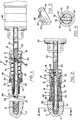
- Figure 1 is a side elevation view, partially broken away, of a tangless helically coiled insert power-driven installation tool, prior to installation of the insert, in accordance with the present invention;
- Figure 2 is a side elevation view, partially broken away, of a tangless helically coiled insert power-driven installation tool, after the insert has been installed in a tapped hole, in accordance with the present invention;
- Figure 3 is a perspective view of the leading end of the pawl of the present invention;
- Figure 4 is a sectional view, with some details omitted, taken along lines 4-4 of Figure 2.
- The present invention is particularly adapted for use with tangless coils which are used, for example, where a steel alloyed bolt having conventional threads is desired to be fastened into a material of relatively softer alloy, such as aluminum.
- As illustrated in figures 1 and 2, the power-driven
installation tool 10 of the present invention is attached to aprime mover 42, which is not part of the invention and, therefore, is illustrated in dash lines. The prime mover may be an electric driver, e.g., manufactured by Hios as Model SB 650C. Thetool 10 of the present invention comprises atubular body member 12, amandrel assembly 14 insertable into the tubular body and adapted to receive a tangless insert, a sleeve member reciprocating in the direction of the longitudinal axis of themandrel assembly 14, abearing member 50 at the front of the tubular body and an adjusting means 16 movable along themandrel assembly 14 wherein the depth to which the insert 11 can be driven is adjustable within certain limits. Thetubular body member 12 provides, in part, the operator with a means for supporting themandrel assembly 14 in order to install the insert correctly during operation. Thetubular body member 12 may includewrenching flats 41 for securing thetool 10 while moving the adjusting means 16. - The
mandrel assembly 14 is insertable into thetubular body member 12 and is adapted to receive the tangless insert for installation into a tapped hole. Themandrel assembly 14 comprises acylindrical rod 20 having a shank end adapted to be received in the chuck of theprime mover 42. Thelead end 22 of therod 20, at the end opposite theshank end 24, is threaded and has a diameter according to the inner diameter that insert 11 will have when it is in its contracted state and installed in a tappedhole 15 of theparent material 17. Thus, the diameter oflead end 22 is somewhat smaller than the inner coil diameter of insert 11 prior to the application of the tool. - The
sleeve member 18, biased byspring 42 betweenlip 43 and trailingbias adjustment 44, is closely fitted concentrically about thelead end 22 of therod 20 to maintain the helix angle of the insert 11 for a smooth transition of the insert into the tappedhole 15. If thesleeve member 18 fits too loosely around the insert or is omitted, then the helix of the insert will flatten out and the insert will not properly engage the first threads of the parent material. - Further, as illustrated in Figures 1 and 2, an adjusting means 16 serves as a jamb nut with the
end portion 13 of movabletubular body member 12, thereby adjusting the distance that thelead end 22 of therod 20 may project out of thetubular body member 12, thus defining the proper depth to which the insert Il may be installed in a tapped hole. - The
bearing member 50, generally made of nylon and fitting around thering 48 on the front portion of thetubular body member 12', bears against theparent material 17 when the insert 11 is installed to the predetermined depth, and increases the friction on the tool wherein the driving torque is automatically reversed and the mandrel is screwed out of the tapped hole. - In Figures I and 2 the pivotable catch or
pawl 30 of the invention is illustrated within alongitudinal cutout 32 ofmandrel assembly 14. Thecutout 32 generally does not extend through the front end 2'1 of therod 20, but is generally equal in length to thepawl 30. Thepawl 30 is biased within thecutout 32 so that ahook portion 34 protrudes throughaperture 33 and engages therecess 52 of the tangless wire coil insert 11. The pawl is generally biased aboutpivot point 36 bysprings 38 to locate thehook portion 34 into therecess 52 of the insert when the insert is screwed onto thelead end 22 of themandrel assembly 14. - The
pivotal pawl 30 further includeslead ramps 40, shown in Figure 3. Theramp 40 in combination with thetruncated end portion 46 of the insert provides a camming means for pivoting thepawl 30 inwardly. Accordingly, the important feature of thepivotable pawl 30 is that it has the ability to locate thehook portion 34, which generally extends between two peaks of the threaded portion of thelead end 22 of the rod, only in the recess of the insert 11 to threadably drive the insert 11 into a tapped hole. Further, counter rotation of thecylindrical rod 20, when the insert has reached its predetermined depth, allows thepivotal pawl 30 to automatically disengage from the recess of the insert to permit extraction of the tool. Theramp 40 provided adjacent but on the opposite side of the centerline of thepivotal pawl 30 permits therecess 52 of the insert 11 to automatically push thepawl 30 downward upon counter clockwise rotation of thecylindrical rod 20, and thus providing an automatic extraction of thetool 10. - The
pivotable pawl 30 also has anotch 60 rearwardly adjacent thehook portion 34. Thisnotch 60 captures the inner thread of the next adjacent thread to the lead thread of the insert to prevent therecess 52 of the insert from slipping off thehook portion 34 when rearward axial force is applied to the insert. Thus, thisanti-slipback notch 60 assures engagement ofhook portion 34 and the insert. - As illustrated in Figure 4, the
hook portion 34 of thepawl 30 engages therecess 52 of thelead end 54 in order that the insert 11 may be screwed by means of thetool 10 into a tapped hole. Since both free ends of the helical coiled insert haverecesses 52 cut therein, the insert may be inserted in the tool in either direction, thus eliminating the possibility of the operator inserting insert on the tool in the wrong direction. - In order to use the tool for driving an insert 11 into a tapped hole, the insert 11 is screwed onto the
lead end 22 of the'mandrel assembly 14 until thehook 34 contacts therecess 52 of the lead coil. Then the insert is driven into the tapped hole until the bearing contacts the surface of the tapped hole, whereupon the tool automatically reverses out of the insert and the tapped hole. If after an insert has been installed and the tool removed, it becomes necessary to adjust the depth of the insert in the tapped hole, the tool of the present invention may be reinstalled. To reinstall the tool, theramp portion 40 of thepivotal pawl 30 cooperates with a truncatedportion 46 of the free end of the insert 11 to push thepawl 30 in a downward direction. During reinsertion of thetool 10 thepivotal pawl 30 moves along the inner surface of the coil past the truncated portion of the coil, past therecess 52 of the trailing portion of the coil axially along the insert until thehook portion 34 of the pawl again engages the recess at the lead end of the coil.
Claims (2)
Applications Claiming Priority (2)
| Application Number | Priority Date | Filing Date | Title |
|---|---|---|---|
| US06/581,840 US4528737A (en) | 1984-02-21 | 1984-02-21 | Adapter for power tool installation of tangless helically coiled insert |
| US581840 | 1984-02-21 |
Publications (3)
| Publication Number | Publication Date |
|---|---|
| EP0153266A2 true EP0153266A2 (en) | 1985-08-28 |
| EP0153266A3 EP0153266A3 (en) | 1987-07-15 |
| EP0153266B1 EP0153266B1 (en) | 1990-01-10 |
Family
ID=24326779
Family Applications (1)
| Application Number | Title | Priority Date | Filing Date |
|---|---|---|---|
| EP85630009A Expired - Lifetime EP0153266B1 (en) | 1984-02-21 | 1985-02-15 | Adapter for power tool installation of tangless helically coiled insert |
Country Status (12)
| Country | Link |
|---|---|
| US (1) | US4528737A (en) |
| EP (1) | EP0153266B1 (en) |
| JP (1) | JPS60191777A (en) |
| KR (1) | KR880001935B1 (en) |
| AU (1) | AU566296B2 (en) |
| BR (1) | BR8500728A (en) |
| CA (1) | CA1232714A (en) |
| DE (1) | DE3575271D1 (en) |
| ES (1) | ES284752Y (en) |
| IL (1) | IL74381A (en) |
| MX (1) | MX158441A (en) |
| ZA (1) | ZA851321B (en) |
Cited By (6)
| Publication number | Priority date | Publication date | Assignee | Title |
|---|---|---|---|---|
| WO2006077120A1 (en) * | 2005-01-20 | 2006-07-27 | Böllhoff Verbindungstechnik GmbH | Tool for inserting and/or removing a helically coiled wire insert |
| WO2013007498A1 (en) | 2011-07-14 | 2013-01-17 | Böllhoff Verbindungstechnik GmbH | Tool for inserting or removing a tang-free wire thread insert |
| EP2599590A4 (en) * | 2010-07-30 | 2014-01-22 | Nippon Sprew Co Ltd | RELATED THREAD INSERT TOOL WITHOUT TAIL |
| WO2018028939A1 (en) | 2016-08-10 | 2018-02-15 | Böllhoff Verbindungstechnik GmbH | Tool for inserting and/or removing a wire thread insert |
| US10807576B2 (en) | 2016-11-09 | 2020-10-20 | Allison Transmission, Inc. | Brake actuator-based prognostic system and method thereof |
| US11565391B2 (en) * | 2016-12-22 | 2023-01-31 | Böllhoff Verbindungstechnik GmbH | Installation tool for a wire thread insert |
Families Citing this family (24)
| Publication number | Priority date | Publication date | Assignee | Title |
|---|---|---|---|---|
| US4645398A (en) * | 1983-09-16 | 1987-02-24 | Rexnord Inc. | Tangless helically coiled insert |
| US4768270A (en) * | 1986-12-16 | 1988-09-06 | Rexnord, Inc. | Installation tool for helical coil inserts |
| US5040277A (en) * | 1989-12-18 | 1991-08-20 | Deutsch Al | Combined installation and swaging tool |
| US5456145A (en) * | 1993-02-16 | 1995-10-10 | Kato Spring Works Company, Ltd. | Installation tool for tangless helically coiled insert |
| US5830221A (en) * | 1996-09-20 | 1998-11-03 | United States Surgical Corporation | Coil fastener applier |
| WO1998011814A2 (en) * | 1996-09-20 | 1998-03-26 | United States Surgical Corporation | Coil fastener applier and remover |
| US6000114A (en) * | 1997-12-31 | 1999-12-14 | Emhart Inc. | Insertion tool |
| DE19813705A1 (en) * | 1998-03-27 | 1999-11-25 | Boellhoff Gmbh | Process to position a helicoil in a work piece and associated tool |
| US6367138B1 (en) * | 1999-09-15 | 2002-04-09 | Emhart Inc. | Power installation tool for helical coil inserts |
| US7634844B2 (en) * | 2006-04-19 | 2009-12-22 | Newfrey Llc | Adjustable prewinder assembly for wire insert installation tool |
| US20080104814A1 (en) * | 2006-11-07 | 2008-05-08 | Stanley Buchanan | Semiautomatic installation tool |
| JP2009291860A (en) * | 2008-06-03 | 2009-12-17 | Advanex Inc | Inserting tool for insert with tongue |
| US8495807B2 (en) * | 2009-06-25 | 2013-07-30 | Newfrey Llc | Retractable prewinder assembly with infinite adjustability for installation of helically coiled wire inserts |
| JP5815471B2 (en) * | 2012-05-29 | 2015-11-17 | 日本スプリュー株式会社 | Tongue-free spiral coil insert extraction tool |
| US9897347B2 (en) * | 2013-03-15 | 2018-02-20 | Thomas Scott Breidenbach | Screw-in geothermal heat exchanger systems and methods |
| JP5873525B2 (en) * | 2013-09-02 | 2016-03-01 | 株式会社アドバネクス | Tool for tongueless coil thread |
| DE102013219013A1 (en) * | 2013-09-20 | 2015-03-26 | Böllhoff Verbindungstechnik GmbH | Spring connecting element |
| CN104723274B (en) * | 2013-12-24 | 2017-03-08 | 北京机床所精密机电有限公司 | A kind of filament spinning component attaching/detaching apparatus |
| US10040182B2 (en) * | 2014-01-21 | 2018-08-07 | Engineered Inserts & Systems, Inc. | System and method for installing a manifold plug |
| US9597787B2 (en) | 2014-04-07 | 2017-03-21 | Newfrey Llc | Iinsertion tool |
| CN110900505A (en) * | 2019-10-27 | 2020-03-24 | 北京点域科技有限公司 | Dismounting device for printing machine |
| DE102020118057B4 (en) | 2020-02-07 | 2024-05-08 | Völkel GmbH | Tool for installing and/or removing a pinless thread insert |
| CN111283600A (en) * | 2020-04-03 | 2020-06-16 | 浙江舒康科技有限公司 | Anti-falling screwdriver |
| CN116276764B (en) * | 2022-10-19 | 2025-05-13 | 江苏拓米洛高端装备股份有限公司 | Hole sleeve mounting method based on hole sleeve mounting device |
Family Cites Families (10)
| Publication number | Priority date | Publication date | Assignee | Title |
|---|---|---|---|---|
| US1627301A (en) * | 1924-09-02 | 1927-05-03 | Wood Gleason | Screw driver |
| US1676755A (en) * | 1925-09-18 | 1928-07-10 | Walton Alfred Leonard | Game apparatus |
| US2390524A (en) * | 1944-05-30 | 1945-12-11 | Aircraft Screw Prod Co | Insert assembling tool |
| CH251468A (en) * | 1944-09-23 | 1947-10-31 | Aircraft Screw Prod Co | Tool for screwing a wire helix into a threaded hole. |
| US2392843A (en) * | 1944-10-25 | 1946-01-15 | Aircraft Screw Prod Co | Insert securing tool |
| US2586805A (en) * | 1949-03-02 | 1952-02-26 | Heli Coil Corp | Inserting tool for tangless coils |
| US2584118A (en) * | 1950-05-27 | 1952-02-05 | Heli Coil Corp | Tool for inserting screw thread linings |
| US2832129A (en) * | 1954-01-11 | 1958-04-29 | Heli Coil Corp | Tool for inserting wire coil screw threads |
| US3111751A (en) * | 1961-10-16 | 1963-11-26 | Heli Coil Corp | Power inserting tool |
| JPS5555980U (en) * | 1978-10-11 | 1980-04-16 |
-
1984
- 1984-02-21 US US06/581,840 patent/US4528737A/en not_active Expired - Lifetime
-
1985
- 1985-02-15 BR BR8500728A patent/BR8500728A/en not_active IP Right Cessation
- 1985-02-15 EP EP85630009A patent/EP0153266B1/en not_active Expired - Lifetime
- 1985-02-15 DE DE8585630009T patent/DE3575271D1/en not_active Expired - Lifetime
- 1985-02-19 IL IL74381A patent/IL74381A/en not_active IP Right Cessation
- 1985-02-20 MX MX204387A patent/MX158441A/en unknown
- 1985-02-20 AU AU38992/85A patent/AU566296B2/en not_active Expired
- 1985-02-20 ES ES1985284752U patent/ES284752Y/en not_active Expired
- 1985-02-21 CA CA000474840A patent/CA1232714A/en not_active Expired
- 1985-02-21 JP JP60031667A patent/JPS60191777A/en active Granted
- 1985-02-21 ZA ZA851321A patent/ZA851321B/en unknown
- 1985-02-21 KR KR1019850001057A patent/KR880001935B1/en not_active Expired
Cited By (14)
| Publication number | Priority date | Publication date | Assignee | Title |
|---|---|---|---|---|
| WO2006077120A1 (en) * | 2005-01-20 | 2006-07-27 | Böllhoff Verbindungstechnik GmbH | Tool for inserting and/or removing a helically coiled wire insert |
| EP2599590A4 (en) * | 2010-07-30 | 2014-01-22 | Nippon Sprew Co Ltd | RELATED THREAD INSERT TOOL WITHOUT TAIL |
| JP2014520678A (en) * | 2011-07-14 | 2014-08-25 | ボルホフ・フェルビンダンクシュテヒニーク・ゲゼルシャフト・ミット・ベシュレンクテン・ハフツング | Tool for attaching and detaching a wire thread insert without a tongue, its manufacturing method, and method for manually changing the entrainment blade of this tool |
| DE102011051846B4 (en) * | 2011-07-14 | 2013-01-24 | Böllhoff Verbindungstechnik GmbH | Tool for installing or removing a tangless wire thread insert, method of manufacture therefor and method of manually changing a picking blade of this tool |
| DE102011051846A1 (en) | 2011-07-14 | 2013-01-17 | Böllhoff Verbindungstechnik GmbH | Tool for installing or removing a tangless wire thread insert, method of manufacture therefor and method of manually changing a picking blade of this tool |
| CN103747920A (en) * | 2011-07-14 | 2014-04-23 | 伯尔霍夫连接技术有限公司 | Tool for installing or removing capless wire thread inserts |
| WO2013007498A1 (en) | 2011-07-14 | 2013-01-17 | Böllhoff Verbindungstechnik GmbH | Tool for inserting or removing a tang-free wire thread insert |
| CN103747920B (en) * | 2011-07-14 | 2016-12-21 | 伯尔霍夫连接技术有限公司 | Tool for installing or removing capless wire thread inserts |
| US9764454B2 (en) | 2011-07-14 | 2017-09-19 | Böllhoff Verbindungstechnik GmbH | Tool for inserting or removing a tang-free wire thread insert, production method therefor and method for manually replacing an entraining blade of this tool |
| WO2018028939A1 (en) | 2016-08-10 | 2018-02-15 | Böllhoff Verbindungstechnik GmbH | Tool for inserting and/or removing a wire thread insert |
| DE102016114824A1 (en) | 2016-08-10 | 2018-02-15 | Böllhoff Verbindungstechnik GmbH | Tool for installing or removing a wire thread insert and manufacturing method therefor |
| US11345004B2 (en) | 2016-08-10 | 2022-05-31 | Böllhoff Verbindungstechnik GmbH | Tool for inserting and/or removing a wire thread insert |
| US10807576B2 (en) | 2016-11-09 | 2020-10-20 | Allison Transmission, Inc. | Brake actuator-based prognostic system and method thereof |
| US11565391B2 (en) * | 2016-12-22 | 2023-01-31 | Böllhoff Verbindungstechnik GmbH | Installation tool for a wire thread insert |
Also Published As
| Publication number | Publication date |
|---|---|
| MX158441A (en) | 1989-01-31 |
| IL74381A0 (en) | 1985-05-31 |
| KR880001935B1 (en) | 1988-10-04 |
| US4528737A (en) | 1985-07-16 |
| CA1232714A (en) | 1988-02-16 |
| EP0153266A3 (en) | 1987-07-15 |
| JPH0438543B2 (en) | 1992-06-24 |
| ZA851321B (en) | 1986-10-29 |
| JPS60191777A (en) | 1985-09-30 |
| BR8500728A (en) | 1985-10-08 |
| DE3575271D1 (en) | 1990-02-15 |
| KR850007034A (en) | 1985-10-30 |
| IL74381A (en) | 1987-03-31 |
| ES284752Y (en) | 1987-01-16 |
| ES284752U (en) | 1985-09-01 |
| AU3899285A (en) | 1985-09-05 |
| AU566296B2 (en) | 1987-10-15 |
| EP0153266B1 (en) | 1990-01-10 |
Similar Documents
| Publication | Publication Date | Title |
|---|---|---|
| US4528737A (en) | Adapter for power tool installation of tangless helically coiled insert | |
| US4553302A (en) | Installation tool, tangless helically coiled insert | |
| CA1232715A (en) | Removal tool for tangless helically coiled insert | |
| AU656459B2 (en) | Tools for installation of both tanged and tangless wire inserts | |
| AU676044B2 (en) | Screwdriver with replaceable bit assembly | |
| EP0615818B1 (en) | Installation tool for tangless helically coiled insert | |
| KR100200383B1 (en) | Installation tool for helical coil inserts | |
| EP2599590A1 (en) | Tangless helical coil insert inserting tool | |
| US3348293A (en) | Wire coil installing tool | |
| US6321433B1 (en) | Double bevel prewinder mandrel | |
| EP2130650A1 (en) | Tanged insert insertion tool | |
| US20030024594A1 (en) | Prewinder apparatus for installation tools | |
| CA2275131C (en) | Socket for lever removal of screwdriver bit | |
| GB2150476A (en) | Inserting threaded inserts | |
| HK1168573B (en) | Insertion tool for tangless spiray coil insert |
Legal Events
| Date | Code | Title | Description |
|---|---|---|---|
| PUAI | Public reference made under article 153(3) epc to a published international application that has entered the european phase |
Free format text: ORIGINAL CODE: 0009012 |
|
| AK | Designated contracting states |
Designated state(s): BE CH DE FR GB IT LI NL SE |
|
| PUAL | Search report despatched |
Free format text: ORIGINAL CODE: 0009013 |
|
| AK | Designated contracting states |
Kind code of ref document: A3 Designated state(s): BE CH DE FR GB IT LI NL SE |
|
| 17P | Request for examination filed |
Effective date: 19871123 |
|
| 17Q | First examination report despatched |
Effective date: 19881019 |
|
| RAP1 | Party data changed (applicant data changed or rights of an application transferred) |
Owner name: REXNORD HOLDINGS INC. |
|
| GRAA | (expected) grant |
Free format text: ORIGINAL CODE: 0009210 |
|
| AK | Designated contracting states |
Kind code of ref document: B1 Designated state(s): BE CH DE FR GB IT LI NL SE |
|
| ET | Fr: translation filed | ||
| REF | Corresponds to: |
Ref document number: 3575271 Country of ref document: DE Date of ref document: 19900215 |
|
| ITF | It: translation for a ep patent filed | ||
| PLBE | No opposition filed within time limit |
Free format text: ORIGINAL CODE: 0009261 |
|
| STAA | Information on the status of an ep patent application or granted ep patent |
Free format text: STATUS: NO OPPOSITION FILED WITHIN TIME LIMIT |
|
| 26N | No opposition filed | ||
| ITTA | It: last paid annual fee | ||
| REG | Reference to a national code |
Ref country code: GB Ref legal event code: 732E |
|
| NLT1 | Nl: modifications of names registered in virtue of documents presented to the patent office pursuant to art. 16 a, paragraph 1 |
Owner name: RHI HOLDINGS, INC. TE CHANTILLY, VIRGINIE, VER. ST |
|
| REG | Reference to a national code |
Ref country code: CH Ref legal event code: PUE Owner name: FAIRCHILD INDUSTRIES INC., - DANN AN - VSI CORPORA Ref country code: CH Ref legal event code: PFA Free format text: RHI HOLDINGS, INC. |
|
| NLS | Nl: assignments of ep-patents |
Owner name: FAIRCHILD INDUSTRIES, INC. TE CHANTILLY, VIRGINIE, |
|
| NLS | Nl: assignments of ep-patents |
Owner name: VSI CORPORATION TE CHANTILLY, VIRGINIE, VER.ST.V.A |
|
| NLS | Nl: assignments of ep-patents |
Owner name: KATO SPRINGS WORKS COMPANY LTD. TE TOKIO, JAPAN. |
|
| BECA | Be: change of holder's address |
Free format text: 940602 *KATO SPRING WORKS CY LTD:1-3 1-CHOME HIGASHI-TABATA KITA-KU, TOKYO |
|
| BECH | Be: change of holder |
Free format text: 940602 *KATO SPRING WORKS CY LTD:1-3 1-CHOME HIGASHI-TABATA KITA-KU, TOKYO |
|
| EAL | Se: european patent in force in sweden |
Ref document number: 85630009.0 |
|
| REG | Reference to a national code |
Ref country code: FR Ref legal event code: TP Ref country code: FR Ref legal event code: CD Ref country code: FR Ref legal event code: CA |
|
| REG | Reference to a national code |
Ref country code: FR Ref legal event code: TP |
|
| ITPR | It: changes in ownership of a european patent |
Owner name: CESSIONE;VSI CORPORATION |
|
| REG | Reference to a national code |
Ref country code: GB Ref legal event code: IF02 |
|
| PGFP | Annual fee paid to national office [announced via postgrant information from national office to epo] |
Ref country code: NL Payment date: 20040116 Year of fee payment: 20 |
|
| PGFP | Annual fee paid to national office [announced via postgrant information from national office to epo] |
Ref country code: GB Payment date: 20040211 Year of fee payment: 20 |
|
| PGFP | Annual fee paid to national office [announced via postgrant information from national office to epo] |
Ref country code: SE Payment date: 20040219 Year of fee payment: 20 Ref country code: FR Payment date: 20040219 Year of fee payment: 20 |
|
| PGFP | Annual fee paid to national office [announced via postgrant information from national office to epo] |
Ref country code: CH Payment date: 20040223 Year of fee payment: 20 |
|
| PGFP | Annual fee paid to national office [announced via postgrant information from national office to epo] |
Ref country code: BE Payment date: 20040323 Year of fee payment: 20 |
|
| PGFP | Annual fee paid to national office [announced via postgrant information from national office to epo] |
Ref country code: DE Payment date: 20040331 Year of fee payment: 20 |
|
| PG25 | Lapsed in a contracting state [announced via postgrant information from national office to epo] |
Ref country code: LI Free format text: LAPSE BECAUSE OF EXPIRATION OF PROTECTION Effective date: 20050214 Ref country code: GB Free format text: LAPSE BECAUSE OF EXPIRATION OF PROTECTION Effective date: 20050214 Ref country code: CH Free format text: LAPSE BECAUSE OF EXPIRATION OF PROTECTION Effective date: 20050214 |
|
| PG25 | Lapsed in a contracting state [announced via postgrant information from national office to epo] |
Ref country code: NL Free format text: LAPSE BECAUSE OF EXPIRATION OF PROTECTION Effective date: 20050215 |
|
| BE20 | Be: patent expired |
Owner name: *KATO SPRING WORKS CY LTD Effective date: 20050215 |
|
| REG | Reference to a national code |
Ref country code: GB Ref legal event code: PE20 |
|
| REG | Reference to a national code |
Ref country code: CH Ref legal event code: PL |
|
| EUG | Se: european patent has lapsed | ||
| NLV7 | Nl: ceased due to reaching the maximum lifetime of a patent |
Effective date: 20050215 |
|
| BE20 | Be: patent expired |
Owner name: *KATO SPRING WORKS CY LTD Effective date: 20050215 |