EP0153124B1 - Akusto-optische Frequenzverschieber - Google Patents
Akusto-optische Frequenzverschieber Download PDFInfo
- Publication number
- EP0153124B1 EP0153124B1 EP85300904A EP85300904A EP0153124B1 EP 0153124 B1 EP0153124 B1 EP 0153124B1 EP 85300904 A EP85300904 A EP 85300904A EP 85300904 A EP85300904 A EP 85300904A EP 0153124 B1 EP0153124 B1 EP 0153124B1
- Authority
- EP
- European Patent Office
- Prior art keywords
- fiber
- acoustic wave
- acoustic
- wave
- frequency shifter
- Prior art date
- Legal status (The legal status is an assumption and is not a legal conclusion. Google has not performed a legal analysis and makes no representation as to the accuracy of the status listed.)
- Expired - Lifetime
Links
- 239000000835 fiber Substances 0.000 claims abstract description 190
- 239000013307 optical fiber Substances 0.000 claims abstract description 29
- 230000010287 polarization Effects 0.000 claims description 41
- 238000010897 surface acoustic wave method Methods 0.000 claims description 18
- 239000000463 material Substances 0.000 claims description 17
- 239000000758 substrate Substances 0.000 claims description 17
- 230000003287 optical effect Effects 0.000 claims description 16
- 238000000034 method Methods 0.000 claims description 11
- 230000008878 coupling Effects 0.000 description 29
- 238000010168 coupling process Methods 0.000 description 29
- 238000005859 coupling reaction Methods 0.000 description 29
- 230000003068 static effect Effects 0.000 description 8
- VYPSYNLAJGMNEJ-UHFFFAOYSA-N Silicium dioxide Chemical compound O=[Si]=O VYPSYNLAJGMNEJ-UHFFFAOYSA-N 0.000 description 7
- 230000001902 propagating effect Effects 0.000 description 6
- 239000010453 quartz Substances 0.000 description 6
- XUIMIQQOPSSXEZ-UHFFFAOYSA-N Silicon Chemical compound [Si] XUIMIQQOPSSXEZ-UHFFFAOYSA-N 0.000 description 4
- 230000006835 compression Effects 0.000 description 4
- 238000007906 compression Methods 0.000 description 4
- 229910052710 silicon Inorganic materials 0.000 description 4
- 239000010703 silicon Substances 0.000 description 4
- 229910052782 aluminium Inorganic materials 0.000 description 3
- XAGFODPZIPBFFR-UHFFFAOYSA-N aluminium Chemical compound [Al] XAGFODPZIPBFFR-UHFFFAOYSA-N 0.000 description 3
- 238000013459 approach Methods 0.000 description 3
- 230000008859 change Effects 0.000 description 3
- 238000013461 design Methods 0.000 description 3
- 230000000694 effects Effects 0.000 description 3
- 239000011358 absorbing material Substances 0.000 description 2
- 230000001186 cumulative effect Effects 0.000 description 2
- 238000010586 diagram Methods 0.000 description 2
- 229920006335 epoxy glue Polymers 0.000 description 2
- 230000003993 interaction Effects 0.000 description 2
- 238000005259 measurement Methods 0.000 description 2
- 239000002480 mineral oil Substances 0.000 description 2
- 235000010446 mineral oil Nutrition 0.000 description 2
- 230000010355 oscillation Effects 0.000 description 2
- 239000000126 substance Substances 0.000 description 2
- 230000001629 suppression Effects 0.000 description 2
- 239000004593 Epoxy Substances 0.000 description 1
- 238000004026 adhesive bonding Methods 0.000 description 1
- 230000008901 benefit Effects 0.000 description 1
- 238000005253 cladding Methods 0.000 description 1
- 230000003247 decreasing effect Effects 0.000 description 1
- 238000011161 development Methods 0.000 description 1
- 239000005350 fused silica glass Substances 0.000 description 1
- 239000003292 glue Substances 0.000 description 1
- 229910052738 indium Inorganic materials 0.000 description 1
- 238000003825 pressing Methods 0.000 description 1
- 238000012360 testing method Methods 0.000 description 1
Images


Classifications
-
- G—PHYSICS
- G02—OPTICS
- G02B—OPTICAL ELEMENTS, SYSTEMS OR APPARATUS
- G02B26/00—Optical devices or arrangements for the control of light using movable or deformable optical elements
-
- G—PHYSICS
- G02—OPTICS
- G02F—OPTICAL DEVICES OR ARRANGEMENTS FOR THE CONTROL OF LIGHT BY MODIFICATION OF THE OPTICAL PROPERTIES OF THE MEDIA OF THE ELEMENTS INVOLVED THEREIN; NON-LINEAR OPTICS; FREQUENCY-CHANGING OF LIGHT; OPTICAL LOGIC ELEMENTS; OPTICAL ANALOGUE/DIGITAL CONVERTERS
- G02F1/00—Devices or arrangements for the control of the intensity, colour, phase, polarisation or direction of light arriving from an independent light source, e.g. switching, gating or modulating; Non-linear optics
- G02F1/01—Devices or arrangements for the control of the intensity, colour, phase, polarisation or direction of light arriving from an independent light source, e.g. switching, gating or modulating; Non-linear optics for the control of the intensity, phase, polarisation or colour
- G02F1/0128—Devices or arrangements for the control of the intensity, colour, phase, polarisation or direction of light arriving from an independent light source, e.g. switching, gating or modulating; Non-linear optics for the control of the intensity, phase, polarisation or colour based on electro-mechanical, magneto-mechanical, elasto-optic effects
- G02F1/0131—Devices or arrangements for the control of the intensity, colour, phase, polarisation or direction of light arriving from an independent light source, e.g. switching, gating or modulating; Non-linear optics for the control of the intensity, phase, polarisation or colour based on electro-mechanical, magneto-mechanical, elasto-optic effects based on photo-elastic effects, e.g. mechanically induced birefringence
- G02F1/0134—Devices or arrangements for the control of the intensity, colour, phase, polarisation or direction of light arriving from an independent light source, e.g. switching, gating or modulating; Non-linear optics for the control of the intensity, phase, polarisation or colour based on electro-mechanical, magneto-mechanical, elasto-optic effects based on photo-elastic effects, e.g. mechanically induced birefringence in optical waveguides
-
- G—PHYSICS
- G02—OPTICS
- G02B—OPTICAL ELEMENTS, SYSTEMS OR APPARATUS
- G02B6/00—Light guides; Structural details of arrangements comprising light guides and other optical elements, e.g. couplings
- G02B6/24—Coupling light guides
- G02B6/26—Optical coupling means
- G02B6/28—Optical coupling means having data bus means, i.e. plural waveguides interconnected and providing an inherently bidirectional system by mixing and splitting signals
- G02B6/2804—Optical coupling means having data bus means, i.e. plural waveguides interconnected and providing an inherently bidirectional system by mixing and splitting signals forming multipart couplers without wavelength selective elements, e.g. "T" couplers, star couplers
- G02B6/2821—Optical coupling means having data bus means, i.e. plural waveguides interconnected and providing an inherently bidirectional system by mixing and splitting signals forming multipart couplers without wavelength selective elements, e.g. "T" couplers, star couplers using lateral coupling between contiguous fibres to split or combine optical signals
Definitions
- the present invention relates to acousto-optic frequency shifters, and particularly to fiber optic frequency shifters utilizing surface acoustic waves or bulk acoustic waves.
- Optical frequency shifting is typically based upon the Doppler effect, i.e., the change in frqeuency due to relative movement between the source and observer.
- the frequency becomes higher and the wavelength shorter when the source is moving towards the observer, and the frequency becomes lower and the wavelength higher when the source is moving away from the observer.
- the Doppler effect has been heretofore used in bulk optics to cause frequency shifts in lightwaves reflected from wave fronts of acoustic waves propagating through optically transparent bulk media.
- the areas of compression and rarefaction caused by the travelling acoustic wave change the index of refraction in the bulk media so that the incoming light is reflected and/or refracted. Movement of the acoustic wave fronts causes a Doppler shift in the reflected and refracted light, such that the light is shifted in frequency by an amount equal to the frequency of the acoustic wave.
- a standing pressure wave in each cylinder resulted when the cylinders were exited with sinusoidal signals to cause elasto-optic coupling between the polarization modes of the fiber, thereby creating side bands above and below the optical carrier.
- Each cylinder generated one side band that was in phase and another that was out of phase with the side bands created by the other cylinder, such that one side band was strengthened and the other cancelled.
- the Nosu device thus functions by applying pressure to the fiber at discrete intervals along the fiber, specifically at intervals of three-quarters beat length of the fiber.
- the maximum frequency shift obtainable with the Nosu device is equal to the maximum rate which the PZT cylinders can be practically driven.
- the amount of power coupled between polarization modes at each coupling point -i.e., at each PZT cylinder- is quite small, and thus, to couple a significant amount of power a large number of these PZT cylinders would be required, yielding a quite unwieldy and generally impractical device for use in fiber optic systems.
- acousto optic frequency shifters which utilize actual acoustic waves is that, for maximum coupling between modes, the acoustic wavelength should be equal to the fiber beat length.
- the minimum beat length is on the order of 1 mm.
- An acoustic wavelength of 1 mm corresponds to an acoustic frequency of about 1-5 MHz. Accordingly, there is a need in the art for a fiber optic frequency shifter which utilizes actual acoustic waves, but avoids this limitation such that the maximum possible frequency shift is not restricted by the beat length of the fiber.
- a fiber optic frequency shifter comprising an optical fiber having first and second modes which propagate light at first and second velocities, respectively and an acoustic transducer for generating an acoustic wave.
- the frequency shifter of the present invention is characterized in that the transducer is positioned relative to the fiber to cause the wave fronts of the acoustic wave to acoustically contact the fiber at an angle of incidence which is less than 90° but greater than 0°.
- the fiber is preferably a birefringent single mode fiber, whereas the modes are the two orthogonal polarization modes of the birefringent single mode fiber. It is advantageous that the wavelength of the acoustic wave is substantially equal to the beat length of the fiber times the sine of the angle of incidence in order to achieve maximum coupling.
- the acoustic wave may be a bulk acoustic wave.
- the frequency shifter comprises a member having a surface, the fiber being positioned in acoustic contact with the surface and the acoustic wave comprising a surface acoustic wave which propagates along the surface.
- the transducer can be movably mounted for positional adjustment relative to the fiber to selectively vary the angle of incidence of the acoustic wave.
- the angle of incidence is advantageously less than 30°.
- the preferred embodiment of the present invention comprises a substrate for preferentially guiding the acoustic energy of the acoustic wave substantially along the axis of the fiber.
- the substrate is preferably formed from an anisotropic material.
- the acoustic wave causes light input in the first mode to be coupled to the second mode such that the coupled light is shifted in frqeuency by an amount equal to the frequency of the acoustic wave.
- the fiber optic frequency shifter of the present invention also preferably comprises a modal filter for suppressing output light from the frequency shifter in the first mode.
- a method of shifting optical frequency by a high amount by means of a fiber optic frequency shifter comprising an optical fiber having two modes.
- This method comprises the steps of generating an acoustic wave and directing the acoustic wave such that its wave fronts make acoustic contact with the fiber at an angle of incidence which is less than 90° but greater than 0°, so that light input to the optical fiber in one of the two modes is coupled to the other of the two modes and shifted in frequency by an amount equal to the frequency of the acoustic wave.
- the wavelength of the acoustic wave is preferably substantially equal to the beat length of the fiber times the sine of the angle of incidence.
- the acoustic wave may be a bulk acoustic wave.
- the acoustic wave is typically directed to acoustically contact the fiber to cause the frequency shifting, such that the phase propagation direction of the wave is at an angle to the fiber, while the energy propagation direction of the wave is substantially parallel to the fiber.
- the frequency shifter of the present invention utilizes a birefringent single mode optical fiber 10, having a central core 12 of relatively high index of refraction and a surrounding cladding 14 of relatively low index of refraction, as shown in Figure 1.
- birefringent fiber has two orthogonal principle axes of birefringence, each of which corresponds to a polarization mode or optical path through the fiber. These axes are labelled X and Y in Figure 1. Light which is linearly polarized along either of these two axes will remain linearly polarized as it propagates down the fiber. In general, light of any polarization can be regarded as a superposition of these two linearly polarized modes.
- the two polarization modes of birefringent single mode optical fiber propagate light at slightly different velocities. Therefore, the phase of light in the X axis mode will change relative to that in the Y axis mode as the light propagates down the fiber.
- the distance, measured longitudinally along the fiber, required for light in one mode to separate in phase by 360° relative to light in the other mode is commonly referred to as the "beat length" of the fiber.
- the beat length may be defined as follows:
- L is the beat Iength
- ⁇ is the wave length of the light
- An is the difference in index of refraction for the two polarization modes.
- the fiber 10 of the preferred embodiment is a high birefringence fiber having a beat length on the order of 1 mm.
- One common technique for fabricating high birefringence fibers is to draw the fiber such that the core has an elliptical shape, as illustrated by the core 12 in Figure 1.
- High birefringence fibers are advantageous in that the polarization modes are well defined, and thus the polarization of the applied light will be maintained over relatively long lengths of fiber, without significant coupling of light between the polarization modes.
- the polarization modes of a high birefringence fiber may be viewed as independent optical paths through the fiber, which are normally uncoupled such that light is not transferred between them.
- selective coupling of light between the polarization modes of a birefringent single mode fiber may be achieved by applying a force to the birefringent fiber at an angle of about 45° relative to the principle axes of birefringence.
- a force may be applied by squeezing the fiber between two anvils or plates on opposing sides of the fiber.
- Application of such force perturbs the axes of birefringence at the point of force, and causes the axes of birefringence to be rotated through a small angle.
- a ridge structure 20 comprises plural ridges 22, 24, 26 at spaced intervals.
- the fiber 10 is disposed between the ridges 22, 24, 26 and a base block 28, so that the fiber 10 may be squeezed therebetween.
- Application of force to the ridge structure 20 in a direction normal to the axes of the fiber 10 perturb the axes of birefringence at each of the ridges 22, 24, 26 and provides alternate stressed and unstressed regions along the fiber 10 which cause coupling between the two polarization modes of the fiber 10.
- the alternate stressed and unstressed regions provided by the ridge structure 20 of Figure 2 may be alternatively provided by an actual travelling acoustic wave, such as the acoustic wave 30 of Figure 3, which is launched to propagate longitudinally along the axis of the fiber 10.
- the periodicity of the travelling acoustic wave 30 provides alternate regions of compression and rarefaction so as to provide corresponding alternate stressed and unstressed regions in the fiber, and thus, cause coupling between the polarization modes of the fiber.
- the wave length of the acoustic wave 30 be selected such that it is equal to the beat length of the fiber.
- each of the alternate regions of compression and rarefraction will then be one half beat length in length, and thus, each of the alternate stressed and unstressed regions will also be one half beat length in length.
- the acoustic wave 30 of Figure 3 by providing alternate half beat length stressed and unstressed regions along the fiber, cumulatively couples light between the polarization modes of the fiber in much the same manner as the half beat length ridges 22, 24, 26 of Figure 2.
- cumulative coupling will also occur if the wavelength is an odd multiple of beat lengths.
- the fiber stress pattern produced by the travelling acoustic wave 30 of Figure 3 travels down the fiber.
- Such travel of the stress pattern causes the light coupled from one polarization mode to the other to be shifted in frequency much as light from a moving source is Doppler shifted.
- the optical carrier wave and the acoustic wave are heterodyned such that the acoustic frequency and the optical carrier frequency combine both additively and subtractively to provide side bands at the sum and difference frequencies.
- the acoustic wave propagates in the same direction as the light, light coupled from the faster polarization mode to the slower polarization mode is upshifted in frequency, while light propagating from the slower polarization mode to the faster polarization mode is downshifted in frequency. If the acoustic wave propagates in a direction opposite to that of the optical carrier, these relationships are reversed, so that light coupled from the faster mode to the slower mode is downshifted, while light coupled from the slower mode to the faster mode is upshifted.
- Frequency shifted coupling requires that the acoustic wave be properly phased matched to the beat pattern of the optical modes in the fiber.
- phase matching occurs when the acoustic wavelength, as measured along the axis of the fiber (rather than the direction of propagation of the acoustic wave), is equal to the beat length of the fiber.
- the propagation constant of the faster mode (lower index), the slower mode (higher index), and the acoustic wave should satisfy the following relationship: where k, is the propagation constant of the faster mode; k 2 is the propagation constant of the slower mode; and k a is the component of the acoustic propagation constant along the fiber.
- the frequency shifted coupling of light between the polarization modes may be examined mathematically by representing the light in the fast optical mode as cos (wt-k,z), where w is the angular frequency of the light, t is time, and z is the distance along the fiber axis.
- the acoustic wave may be represented as cos( ⁇ a t ⁇ k a z), where 00. is the angular frequency of the acoustic wave.
- the interaction of these two waves leads to a product term proportional to:
- the second term of Expression 3 does not satisfy the phase matching condition of Equation 2, and thus, it is expected that the signal represented by this term will die away.
- the first term is phase matched to the slow mode, in accordance with expression (2) and explicitly indicates that the slow mode is upshifted.
- a similar analysis shows that if th slow mode interacts with the acoustic wave, the expression for the resulting interaction is:
- the second term of Expression 4 like the second term of Expression 3, is not phased matched, however, the remaining term is phased matched to the first mode, in accordance with Equation (2) and explicitly describes a downshifted wave.
- the upper side band will be contained in one polarization, and the lower side band will be contained in the other.
- the desired side band can be selected by passing the output light through a polarizer.
- phase matching requirements indicate that, for an acoustic wave propagating longitudinally down the fiber with the wave fronts normal to the fiber axis, the acoustic wave frequency should be such that its wavelength is equal to the fiber beat length. Since fiber beat lengths are typically on the order 1 mm or more, the maximum available frequency shift from such longitudinally propagating acoustic wave is on the order of only a few megahertz.
- the frequency shifter of the present invention circumvents this limitation by positioning an acoustic transducer 40 to produce an acoustic ave 42, which propagates in a direction, e.g. as indicated by the arrow 43, which is at an angle to the axis 48 of a high birefringence single mode optical fiber 46.
- Such positioning causes the wave fronts 44 of the wave 42 to be directed to acoustically contact the high birefringent single mode optical fiber 46 at an angle 8, referred to herein as "the angle of incidence".
- the term "angle of incidence is defined as the actue angle between a wavefront of an acoustic wave impinging on the fiber and the longitudinal axis of that fiber.
- the wavelength ⁇ . (which is measured in the direction of propagation 43) of the acoustic wave 44 and the angle of incidence, e, are preferably selected such that adjacent wave fronts 44 are spaced by one fiber beat length, L, which is measured in a direction along the fiber axis 48.
- This beat length spacing of the wave fronts 44 satisfies the phase matching conditions set forth above, and thus, the component of acoustic propagation along the fiber axis 48 will satisfy Equation 2, above.
- This arrangement permits the use of much shortrer acoustic wavelengths, and thus, much higher acoustic frequencies than heretofore possible, while still satisfying the phase matching condition.
- simple trigonometry shows that the phase matching condition will be satisfied when:
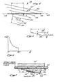
- Equation 5 may be rewritten in terms of the acoustic frequency w a , as follows: where V a is the propagation velocity of the acoustic wave.
- Figure 6 graphically illustrates the relationship between the acoustic frequency and the angle of incidence, and shows that for very small angles of incidence (e.g. a few degrees or a fraction of a degree), the acoustic frequency utilized may be quite high. Note that the acoustic frequency is at a minimum when 8 equals 90° (i.e. when the acoustic wavefronts are normal to the fiber). By way of example, an angle of incidence of 3° would permit use of an acoustic frequency of 95 MHz for a fiber having a 1 mm beat length. Further, by adjustably mounting the acoustic transducer 40 ( Figure 4) the angle of incidence may be varied without disturbing the fiber 46, thus, yielding a variable fiber optic frequency shifter. Such adjustable mounting is also advantageous for tuning the angle of incidence for proper phase matching at the selected frequency.
- propagation phase velocity By directing the wave 42 at an angle relative to the fiber 46, the propagation phase velocity of the wave 42 will be higher in the direction along the fiber axis 48 than along the direction of propagation 43.
- propagation phase velocity is defined as the velocity, measured along a particular line of measurement (e.g. the direction 43 or axis 48), with which the intersection of a wave front (e.g. one of the wave fronts 44) and that axis of measurement move.
- the minimum spacing between the acoustic transducer 40 and the fiber 46, measured in the direction of propagation 43, as indicated by the dimension d, is at least equal to the length of the Fresnel region of the wave 42, so that the wave 42 contacts the fiber 46 in the Fraunhofer region.
- the length of the Fresnel region is determined by the geometry of the transducer, as well as the wavelength of the wave 42.
- the wave fronts are better defined than in the Fresnel region, although the wave tends to diverge rapidly after entering the Fraunhofer region, thereby decreasing in intensity.
- the wave 42 will be well defined at maximum intensity substantially at the juncture between the Fresnel and Fraunhofer regions, and for some applications it may be preferable to place the fiber at such juncture.
- the frequency shifter of the present invention may comprise either a bulk wave device or a surface wave device
- the preferred embodiment is a bulk wave device, as it is possible to generate bulk waves at higher frequencies than surface waves, thereby permitting higher frequency shifts.
- the preferred embodiment comprises a bulk acoustic wave transducer 50 and an aluminum block or pressure plate 52, with a single mode birefringent optical fiber 54 therebetween.
- the transducer 50 and pressure plate 52 are mechanically coupled or clamped together, so as to press against the fiber 54 from opposite sides thereof to ensure good acoustic contact of the transducer 50 with the fiber 54.
- the pressure plate 52 bears against the fiber 54 through a length therealong at least as great as the corresponding length of the transducer 50.
- any suitable means may be used to mechanically couple the transducer 50 and plate 52, such as nuts and bolts (not shown).
- such bolts should be spring loaded to permit adjustment of the static pressure on the optical fiber 54.
- an acoustic coupling gel (not shown) between the fiber 54 and transducer 50 to enhance the acoustic contact.
- the coupling gel may be Sonotrak diagnostic medical ultrasonic scanning couplant, available from Echo Laboratories, Lewistown, Pennsylvania.
- the static pressure exerted on the fiber should be carefully adjusted so that it is just enough for good acoustic contact. Too much pressure may cause a significant amount of unwanted coupling of non-frequency shifted light between the polarization modes.
- the transducer 50 of the preferred embodiment is formed of a wedge-shaped block, e.g. of fused quartz 56, and has a triangular cross section.
- the wedge-shaped block 56 has five flat surfaces, namely, a rectangularly-shaped hypotenuse surface 58, a rectangularly-shaped first side surface 60, a rectangularly-shaped second side surface 62, and a pair of triangularly-shaped end surfaces 64, only one of which is visible in Figure 7.
- the hypotenuse surface 58 forms the hypotenuse edge of the triangularly-shaped cross section
- the side surfaces 60, 62 which are mutually perpendicular, form the side edges of the triangularly-shaped cross section.
- the block 56 is disposed so that the hypotenuse surface 58 contacts the optical fiber 54, preferably such that the axes of birefringence are at 45° relative to the surface 58.
- the end surfaces 64 are perpendicular to the surfaces 58, 60, 62, and are parallel to the longitudinal axis of the optical fiber 54.
- the side surface 60 forms an angle 8 with the hypotenuse surface 58.
- the side surface 62 is opposite this angle 8.
- a thin slab of piezoelectric (PZT) material 66 is bonded between two electrodes 68, 70, and the electrode 70, in turn, is bonded to the first side surface 60 of the quartz block 56.
- the PZT slab is thus poled orthogonal to the first side surface 60 of the quartz block 56 so that, when the electrodes are driven by an electric signal generator (not shown) the PZT slab 66 will oscillate to excite a longitudinal bulk wave having generally planar wavefronts which travel through the quartz wedge at the angle 8 relative to the longitudinal axis of the fiber 54.
- the incident acoustic wave is properly phased matched to couple the two optical modes, as discussed in reference to Figure 4, through proper selection of the angle 8 and the acoustic frequency.
- reflections within the wedge 56 do not produce significant spurious side bands because they are not properly phased matched to the beat pattern of the optical modes.
- the above-described frequency shifter may be utilized to provide single side band modulated light.
- an input light wave, W is first passed through modal filter, e.g. a polarizer 72, to ensure that the light is linearly polarized along one of the principal axes of birefringence of the fiber 54.
- modal filter e.g. a polarizer 72
- the direction of frequency shift i.e. upshift or downshift
- a lens 74 is used to focus light from the polarizer 72 for introduction into the end of the fiber 54.
- a polarization controller 76 is provided just before the acoustic transducer to permit final adjustment of the polarization to compensate for any such perturbation of the axis of birefringence.
- a polarization controller 76 is provided just before the acoustic transducer to permit final adjustment of the polarization to compensate for any such perturbation of the axis of birefringence.
- the fiber optic frequency shifter As the light propagates through the fiber optic frequency shifter, it is at least partially coupled from the mode to which it was input, to the orthogonal mode, and such coupled light is shifted in frequency by an amount equal to the acoustic frequency, in accordance with the discussion in reference to Figures 3-7.
- the light exiting the fiber 54 therefore, will contain frequency shifted light in one mode, and, if the input light was not 100% coupled, non-shifted light in the other mode.
- the light is then passed through a lens 78, for collimation purposes, and then through a modal filter, e.g. polarizer 80, oriented to block the non-shifted light in the original input mode, so that only the shifted light is passed by the polarizer 80 to form an output wave, W o .
- a modal filter e.g. polarizer 80
- the fiber optic frequency shifter of Figure 7 was tested as a single side band modulator utilizing an arrangement similar to that shown in Figure 8.
- the transducer 50 was driven at 15 MHz with 2.25 watts of power.
- the angle of incidence was 13.5° and the fiber beat length was 1.65 mm at 632.8 nm. Both the 632.8 nm carrier and unwanted side band were suppressed by better than 20 db below the desired side band.
- the input polarization and static stress on the fiber by the plate and transducer were carefully adjusted so that the output light at the input optical carrier frqeuency was in the input polarization upon leaving the frequency shifter, so that it could be suppressed by correct adjustment of the output polarizer 80.
- FIG. 9 An alternative embodiment of the present invention, which may be preferable for some applications, is shown in Figure 9.
- the device of Figure 9 is a surface acoustic wave frequency shifter.
- This device comprises a rectangular lower base block 90, e.g. of aluminum, for supporting a single mode birefringent fiber 92.
- a rectangular upper block 94 e.g. of aluminum, is placed on top of the optical fiber, so that the fiber 92 is between the flat upper surface 96 of the lower block 90 and the flat lower surface 98 of the upper block 94.
- Pressure is applied to the upper surface 100 of the upper block 94 to force the surfaces 96, 98 of the blocks 90, 94, respectively, against the optical fiber 92 to ensure good acoustic contact.
- Such pressure may be achieved by applying weights (not shown) to the upper surface 100. Except for the pressure provided by these weights and the weight of the upper block 94 itself, there is no mechanical coupling between the upper and lower blocks, 90, 94. As with the transducer of Figure 7, an acoustic coupling gel between the surface 98 and the fiber 92 may improve acoustic contact.
- An edge bonded PZT transducer 102 is bonded to a side surface 104 of the upper block 94.
- This transducer 102 has electrodes (not shown) bonded to the faces of a PZT slab.
- the PZT which is poled in a direction orthogonal to the lower surface 98 of the upper block 94, will oscillate to induce a surface acoustic wave on the lower surface 98 of the upper block 94, as illustrated by the wave 106 in Figure 9.
- the transducer 102 is positioned at one corner of the block, at the juncture between the lower surface 98 and side surface 104, which is the lower left-hand corner as viewed in Figure 9.
- dampening material 107 may be placed diagonally from the transducer 102, i.e. at the upper right corner as viewed in Figure 9, where the upper surface 100 joins a side surface 108.
- This dampening material 107 will absorb any surface acoustic waves travelling along the surfaces 104, 100, and 108, so that the only surface wave propagating along the surface 98 will be the wave 106.
- the material 107 may be Dux-Seal, available from Johns-Manville, Vernon, California.
- Edge bonded surface acoustic wave transducers are well-known in the art, and are described in various publications such as in an article entitled “Applications of Edge Bonded Transducers to SAW Components", Proceedings of the IEEE, May 1976, pages 627-630.
- the undulating lower surface 98 is forced into intimate contact with the fiber, thereby producing a travelling stress pattern in the fiber.
- the frequency (or wavelength) of the surface acoustic wave 106 is phase matched to the beat length of the fiber 92, light will be coupled from one of the polarization modes of the fiber 92 to the other of the polarization modes, and such coupled light will be frequency shifted by an amount equal to the frequency of the acoustic wave 106.
- the pressure applied to the upper surface 100 of the upper block 94 should be just enough to ensure good acoustic contact, since such pressure may perturb the axes of birefringence of the fiber through the length of the lower surface 98.
- Single side band modulation may be achieved utilizing the same arrangement shown in Figure 8. Test results utilizing a similar arrangement were conducted in which the transducer was driven at a frequency of 1.45 MHz, which yields an acoustic wavelength equal to the beat length of the fiber (1.65 mm at 632.8 nm). Better than 30 db suppression of the unwanted side band was measured.
- Variable amounts of frequency shift may be obtained utilizing the surface wave device of Figure 9 by rotating the upper block relative to the lower block so that the wave fronts of the surface wave 106 acoustically contact the fiber 92 at the selected angle of incidence, which, of course, should be phase matched to the beat length of the fiber, at the particular acoustic wavelength, as discussed in detail in reference to Figure 4.
- Such rotational repositioning of the block 94 may be readily achieved since the upper block 94 and lower block 90 are not mechanically coupled together.
- an optical fiber 110 is affixed, e.g. by epoxy gluing or indium bonding, to the upper surface of a base block 112, formed e.g. of silicon. Silicon is advantageous since it propagates surface waves at a relatively high velocity.
- a shear wave transducer 114 is utilized to generate a surface acoustic wave for propagation along the flat upper surface 116 of the block 112 towards the fiber 110 in a direction e.g. as indicated by the arrow 118.
- Shear wave transducers are well-known in the art, and may comprise e.g. a wedge-shaped block of quartz having a cross section which is a right triangle in shape.
- a LiNb0 3 slab is bonded to the hypotenuse face or surface 122 of the wedge-shaped block 114.
- Electrodes (not shown) are placed on the slab 120 so that the slab 120 is shear polarized in a direction parallel to the face 122.
- Application of an appropriate AC driving signal to the electrodes causes oscillations in the slab 120 which generate shaer waves in the quartz block.
- the shear waves are directed downward, towards the upper surface 116 of the block 112, at an angle determined by the shape of the wedge 114.
- the shear waves induce a surface acoustic wave in the surface 116, which propagate toward the fiber in the direction indicated by the arrow 118.
- shear wave wedge transducers may be found in the literature, such as in a report by Fraser entitled “Design of Efficient, Broadband Ultrasonic Transducers", Ginzton Lab Report #2973 (May 1979), available through the W. W. Hansen Laboratories Reports Office, Edward L. Ginzton Laboratory, Stanford University, Stanford, California 94305, and from University Microfilms International, 300 N. Zeeb Road, Ann Arbor, Michigan 48106.
- An alternative approach, utilizing a longitudinal wave wedge transducer is described in an article by Fraser et al., entitled “The Design of Efficient Broad Band Wedge Transducers", Applied Physics Letters, Vol. 32, No. 11, (1 June, 1978), pages 698-700, and in an article by Cook et al., entitled “Surface Waves at Ultrasonic Frequencies", ASTM Bulletin, TP 127 (May 1954) pages 81-84.
- the frequency shifter shown in Figure 10 is advantageous in that the freestanding mounting of the fiber does not depend upon any static stresses to hold the fiber in place, and thus, perturbation of the axis of birefringence is reduced or eliminated.
- the direction or propagation of the surface acoustic wave, indicated by the arrow 118, and thus the angle of incidence can be changed by repositioning the wedge-shaped block 114 on the surface 116, since the block 114 and surface 116 are not mechanically coupled.
- the embodiment of Figure 10 permits variable frequency shifting, and the selected frequency shift can be obtained by adjusting the direction of propagation of the surface acoustic wave to yield the angle of incidence required for phase matching at the particular frequency desired. It is preferable to place an absorbing material (not shown) such as black wax, along the sides 124, 125 of the block 112 to prevent backward reflection of the acoustic wave from such sides 124, 125.
- one method of affixing the fiber 110 to the surface 116 is by means of a bonding substance, e.g. epoxy glue 126.
- a bonding substance e.g. epoxy glue 126.
- pressure e.g. by means of weights to the top of the fiber so as to press the fiber 110 against the surface 116 with a constant force while the glude 126 is curing.
- weights should of course, be removed after the glue has cured, and prior to using the device as a frequency shifter. Once the weights are removed, the bonding substance 126 will be in tension, so as to draw the fiber against the surface 116 for good acoustic contact.
- the fiber 110 should preferably be affixed such that the axes of birefringence are at 45° relative to the surface 116 as indicated in Figure 11.
- phase propagation direction is ordinarily used to define a direction which is normal to the acoustic wave front, and will be used in that sense for the pruposes of the present discussion.
- the phase propagation direction in Figure 4 is shown by the arrow 43
- the corresponding phase propagation direction in Figure 10 is shown by the arrow 118. If an acoustic wave propagates through an isotropic material, such as quartz, the direction of acoustic energy flow or propagation will be the same as the phase propagation direction, i.e. in a direction normal to the acoustic wave fronts.
- the acoustic energy propagation direction will, in general, be different than the phase progation direction.
- the energy propagation direction of an anisotropic material is determined by the atomic or crystalline structure of the material.
- anisotropic cause the acoustic energy to preferentially propagate in a direction referred to herein as the energy propagation direction which is not the same as the phase propagation direction.
- each phase propagation direction will have a corresponding energy propagation direction, both of which depend on the relative orientation of the crystalline structure and the transducer.
- the silicon block 112 of Figure 10 is anisotropic, it is only weakly so, and thus, the phase propagation directions and energy propagation directions will be substantially similar. Further, the orientation of the atomic structure at the surface 116, if desired, may be chosen so that the silicon behaves as an isotropic material.
- a substrate 140 may be formed from a thin strip of a strongly anisotropic material such as LiNb0 3 .
- An optical fiber 142 is mounted on the surface 143 of the substrate 140, (e.g. in the manner described in reference to Figure 11) such that the longitudinal axis of the fiber 142 is parallel to the energy propagation direction of the anisotropic substrate 140, which direction is illustrated by the arrow 144 in Figure 12.
- the substrate 140 is formed as a thin rectangular strip with longitudinal sides 146 parallel to the axis of the fiber 142 and the direction of energy propagation 144.
- a surface acoustic wave 148 is produced by an interdigital transducer 150.
- this transducer 150 must be properly positioned relative to the crystalline structure of the substrate surface 143 so as to yield the desired energy propagation direction 144 and the desired phase propagation direction 152.
- the transducer is positioned to propagate the acoustic wave energy longitudinally along the surface 143, in the direction 144.
- the transducer 150 is also positioned so that phase propagation direction 152 for the acoustic wave is at an angle of incidence 6 to the fiber 142.
- the wave fronts 149 of the acoustic wave 148 will thus be directed at an angle relative to the fiber 142 (in the same manner as the wave fronts 44 in Figure 4), the acoustic energy of those wave fronts will propagate longitudinally down the fiber in the direction 144. This ensures that the acoustic wave fronts 149 will acoustically contact the fiber 142 substantially throughout the length of the fiber-substrate interface.
- the wave fronts 149 may not be of sufficient length to contact the fiber 142 throughout such interface, and would tend to propagate to the side 146 of the substrate 140, rather than to the end 154 opposite the transducer 150.
- utilizing an anisotropic material for the substrate 140 is highly advantageous.
- interdigital transducer 150 may comprise thin electrodes 156, 158 which are bonded directly to the surface 143 between the substrate 140 and the fiber 142 at the end 160 of the substrate 140, which is opposite the end 154.
- Interdigital transducers are well known in the art and are described in articles by W. R. Smith, et al. entitled “Analysis of Interdigital Surface Wave Transducer by Use of an Equivalent Circuit Model” and “Design of Surface Wave Delay Lines with Interdigital Transducers", IEEE Transactions on Microwave Theory and Techniques, Vol. MTT-17, No. 11, pages 856-864 and 865-873, respectively, (November 1969).
- the electrodes for interdigital transducers each typically comprise a set of electrically connected finger-like projections which are interleaved with a similar set of electrically connected finger-like projections of the other electrode, as shown in Figure 12.
- the electrodes 156, 158 are driven by an A.C. signal generator to cause oscillations in the substrate 140 which produce the surface acoustic wave 148.
- an acoustic absorbing material (not shown), such as black wax, along the edge of the substrate 140 at the end 154 to prevent unwanted reflections of the acoustic wave 148.
- nonbirefringent fiber may alternatively be utilized in the present invention.
- the fiber should be selected to support two modes, namely, the first and second order modes for the particular wavelength of light utilized.
- frequency shifted light will be coupled between the two modes, i.e. from the first order mode to the second order mode.
- Such coupling is due to perturbation of the modes caused by the acoustic stresses as they travel down the fiber.
- a more detailed explanation of the theory for such modal coupling is discussed in an article entitled, "Two-mode fiber modal coupler", R. C. Youngquist, et aI, Optics Letters, Vol. 9, No. 5, May 1984, pp. 177-179, which is hereby incorporated by reference herein.
- a nonbirefringent fiber may thus be alternatively utilized in the single side band modulator of Figure 8.
- the polarization controller 76 and polarizers 72, 80 are not required.
- the input light should be launched exclusively in the second order mode of the fiber, and a modal filter, e.g. mode stripper (not shown), should be placed at the output end of the device to suppress the second order mode such that only frequency shifted light coupled to the first order mode is output from the device.
Landscapes
- Physics & Mathematics (AREA)
- General Physics & Mathematics (AREA)
- Optics & Photonics (AREA)
- Nonlinear Science (AREA)
- Mechanical Light Control Or Optical Switches (AREA)
- Optical Integrated Circuits (AREA)
- Developing Agents For Electrophotography (AREA)
- Driving Mechanisms And Operating Circuits Of Arc-Extinguishing High-Tension Switches (AREA)
- Photoreceptors In Electrophotography (AREA)
- Light Guides In General And Applications Therefor (AREA)
- Glass Compositions (AREA)
- Lasers (AREA)
Claims (15)
Priority Applications (1)
| Application Number | Priority Date | Filing Date | Title |
|---|---|---|---|
| AT85300904T ATE56282T1 (de) | 1984-02-17 | 1985-02-11 | Akusto-optische frequenzverschieber. |
Applications Claiming Priority (2)
| Application Number | Priority Date | Filing Date | Title |
|---|---|---|---|
| US06/581,176 US4735485A (en) | 1984-02-17 | 1984-02-17 | Acousto-optic frequency shifter using optical fiber and method of manufacturing same |
| US581176 | 1984-02-17 |
Publications (3)
| Publication Number | Publication Date |
|---|---|
| EP0153124A2 EP0153124A2 (de) | 1985-08-28 |
| EP0153124A3 EP0153124A3 (en) | 1986-07-30 |
| EP0153124B1 true EP0153124B1 (de) | 1990-09-05 |
Family
ID=24324193
Family Applications (1)
| Application Number | Title | Priority Date | Filing Date |
|---|---|---|---|
| EP85300904A Expired - Lifetime EP0153124B1 (de) | 1984-02-17 | 1985-02-11 | Akusto-optische Frequenzverschieber |
Country Status (11)
| Country | Link |
|---|---|
| US (1) | US4735485A (de) |
| EP (1) | EP0153124B1 (de) |
| JP (1) | JPS60242423A (de) |
| KR (1) | KR920007288B1 (de) |
| AT (1) | ATE56282T1 (de) |
| AU (1) | AU3864785A (de) |
| BR (1) | BR8500698A (de) |
| CA (1) | CA1257925A (de) |
| DE (1) | DE3579472D1 (de) |
| IL (1) | IL74304A0 (de) |
| NO (1) | NO850598L (de) |
Families Citing this family (22)
| Publication number | Priority date | Publication date | Assignee | Title |
|---|---|---|---|---|
| US4801189A (en) * | 1983-11-30 | 1989-01-31 | The Board Of Trustees Of The Leland Stanford Junior University | Birefringent fiber narrowband polarization coupler and method of coupling using same |
| US4792207A (en) * | 1983-11-30 | 1988-12-20 | The Board Of Trustees Of The Leland Stanford Junior University | Single mode fiber optic single sideband modulator and method of frequency shifting using same |
| US4832437A (en) * | 1986-01-17 | 1989-05-23 | The Board Of Trustees Of The Leland Stanford Junior University | Fiber optic inter-mode coupling single side band frequency shifter |
| IL81241A0 (en) * | 1986-01-17 | 1987-08-31 | Univ Leland Stanford Junior | Fiber optic inter-mode coupling single side band frequency shifter |
| US4828350A (en) * | 1986-01-17 | 1989-05-09 | The Board Of Trustees Of The Leland Stanford Junior University | Fiber optic mode selector |
| US5022732A (en) * | 1986-01-17 | 1991-06-11 | The Board Of Trustees Of The Leland Stanford Junior University | Fiber optic intermode coupling single sideband frequency shifter |
| US4872738A (en) * | 1986-02-18 | 1989-10-10 | The Board Of Trustees Of The Leland Stanford Junior University | Acousto-optic fiber-optic frequency shifter using periodic contact with a surface acoustic wave |
| US4781425A (en) * | 1986-02-18 | 1988-11-01 | The Board Of Trustees Of The Leland Stanford Junior University | Fiber optic apparatus and method for spectrum analysis and filtering |
| GB8622609D0 (en) * | 1986-09-19 | 1986-10-22 | Rogers A J | Optical fibres |
| US4761049A (en) * | 1986-09-30 | 1988-08-02 | The United States Of America As Represented By The Secretary Of The Navy | Optical waveguide device for frequency shifting and mode conversion |
| US4915468A (en) * | 1987-02-20 | 1990-04-10 | The Board Of Trustees Of The Leland Stanford Junior University | Apparatus using two-mode optical waveguide with non-circular core |
| GB8706272D0 (en) * | 1987-03-17 | 1987-04-23 | Sieger Ltd | Fibre optic telemetry |
| US4976507A (en) * | 1988-06-20 | 1990-12-11 | Mcdonnell Douglas Corporation | Sagnac distributed sensor |
| US4919512A (en) * | 1988-10-17 | 1990-04-24 | Mcdonnell Douglas Corporation | Wavelength shift switch and sensing system |
| US4991923A (en) * | 1989-01-17 | 1991-02-12 | Board Of Trustees Of The Leland Stanford Junior University | Acousto-optic modulator for optical fibers using Hertzian contact with a grooved transducer substrate |
| US5095515A (en) * | 1989-11-20 | 1992-03-10 | George Seaver | Photoelastic optical switch and optical systems employing the optical switch |
| US5016957A (en) * | 1989-11-20 | 1991-05-21 | George Seaver | Photoelastic optical switch and optical systems employing the optical switch and a method of use thereof |
| US5224193A (en) * | 1990-09-20 | 1993-06-29 | International Business Machines Corporation | First order mode frequency doubler system and method |
| US5757987A (en) * | 1997-02-07 | 1998-05-26 | Lucent Technologies Inc. | Acousto-optic modulator for optical waveguides |
| WO2019135787A2 (en) * | 2017-06-30 | 2019-07-11 | The Board Of Trustees Of The Leland Stanford Junior University | Acousto-optic beam steering system |
| CN113156672B (zh) * | 2021-05-08 | 2024-07-19 | 南开大学 | 一种全光纤耦合器的封装结构及封装方法 |
| HRP20250259A1 (hr) | 2022-08-12 | 2025-10-24 | Sveučilište U Zagrebu, Prirodoslovno-Matematički Fakultet | Metoda za podešavanje frekvencije lasera primijenjena u rotacijskom uređaju s optičkim valovodom |
Family Cites Families (12)
| Publication number | Priority date | Publication date | Assignee | Title |
|---|---|---|---|---|
| US3912363A (en) * | 1974-01-29 | 1975-10-14 | Rca Corp | Optical fiber to planar waveguide coupler |
| JPS5241541A (en) * | 1975-09-29 | 1977-03-31 | Nippon Telegr & Teleph Corp <Ntt> | Input-output equipment for optical fibers |
| US4097118A (en) * | 1975-10-30 | 1978-06-27 | Rca Corporation | Optical waveguide coupler employing deformed shape fiber-optic core coupling portion |
| US4018506A (en) * | 1975-11-12 | 1977-04-19 | Rca Corporation | Fiber-optic to planar-waveguide optical coupler |
| JPS5267345A (en) * | 1975-12-01 | 1977-06-03 | Nippon Telegr & Teleph Corp <Ntt> | Mixing device for optical fiber modes |
| US4086484A (en) * | 1976-07-14 | 1978-04-25 | International Telephone And Telegraph Corporation | Optical amplitude modulation modulator |
| US4236786A (en) * | 1978-12-13 | 1980-12-02 | Corning Glass Works | Method of effecting coupling of selected modes in an optical waveguide |
| DE3006102A1 (de) * | 1979-02-19 | 1980-08-28 | Ricoh Kk | Optische steuereinrichtung |
| JPS55155324A (en) * | 1979-05-23 | 1980-12-03 | Ricoh Co Ltd | Optical fiber device |
| US4268116A (en) * | 1979-10-26 | 1981-05-19 | Optelecom Incorporated | Method and apparatus for radiant energy modulation in optical fibers |
| US4588296A (en) * | 1981-10-07 | 1986-05-13 | Mcdonnell Douglas Corporation | Compact optical gyro |
| US4684215A (en) * | 1983-11-30 | 1987-08-04 | The Board Of Trustees Of The Leland Stanford Junior University | Single mode fiber optic single sideband modulator and method of frequency |
-
1984
- 1984-02-17 US US06/581,176 patent/US4735485A/en not_active Expired - Fee Related
-
1985
- 1985-02-11 IL IL74304A patent/IL74304A0/xx unknown
- 1985-02-11 DE DE8585300904T patent/DE3579472D1/de not_active Expired - Lifetime
- 1985-02-11 AT AT85300904T patent/ATE56282T1/de not_active IP Right Cessation
- 1985-02-11 EP EP85300904A patent/EP0153124B1/de not_active Expired - Lifetime
- 1985-02-12 AU AU38647/85A patent/AU3864785A/en not_active Abandoned
- 1985-02-14 BR BR8500698A patent/BR8500698A/pt unknown
- 1985-02-15 CA CA000474395A patent/CA1257925A/en not_active Expired
- 1985-02-15 JP JP60029192A patent/JPS60242423A/ja active Pending
- 1985-02-15 NO NO850598A patent/NO850598L/no unknown
- 1985-02-16 KR KR1019850000977A patent/KR920007288B1/ko not_active Expired
Also Published As
| Publication number | Publication date |
|---|---|
| NO850598L (no) | 1985-08-19 |
| JPS60242423A (ja) | 1985-12-02 |
| US4735485A (en) | 1988-04-05 |
| KR850007121A (ko) | 1985-10-30 |
| KR920007288B1 (ko) | 1992-08-29 |
| EP0153124A3 (en) | 1986-07-30 |
| BR8500698A (pt) | 1985-10-01 |
| CA1257925A (en) | 1989-07-25 |
| IL74304A0 (en) | 1985-05-31 |
| EP0153124A2 (de) | 1985-08-28 |
| AU3864785A (en) | 1985-08-22 |
| DE3579472D1 (de) | 1990-10-11 |
| ATE56282T1 (de) | 1990-09-15 |
Similar Documents
| Publication | Publication Date | Title |
|---|---|---|
| EP0153124B1 (de) | Akusto-optische Frequenzverschieber | |
| US4346965A (en) | Light modulator/deflector using acoustic surface waves | |
| KR920006589B1 (ko) | 광 섬유 주파수 전이기 및 주파수 전이방법 | |
| US4781425A (en) | Fiber optic apparatus and method for spectrum analysis and filtering | |
| US4793676A (en) | Optical fiber acousto-optic amplitude modulator | |
| US3719906A (en) | Dispersive delay lines operating in the shear mode | |
| US4792207A (en) | Single mode fiber optic single sideband modulator and method of frequency shifting using same | |
| Oliner | Waveguides for acoustic surface waves: A review | |
| EP0190923B1 (de) | Optische Faser mit mehreren Windungen als akustooptischer Frequenzschieber | |
| Miyano | Excitation of stripe domain patterns by propagating acoustic waves in an oriented nematic film | |
| Lissenden et al. | Control of low-frequency Lamb wave propagation in plates by boundary condition manipulation | |
| US3419322A (en) | Ultrasonic transducer matching for bragg reflection scanning | |
| US3822929A (en) | Electronically tunable optical filter using acoustic waves | |
| JPH09503599A (ja) | 修正結晶材料を使用して高周波数信号を制御するための表面音波装置 | |
| CA1283570C (en) | Acousto-optic fiber-optic frequency shifter using periodic contact with a surface acoustic wave | |
| US4527866A (en) | Acousto-optic transducer | |
| Renosi et al. | Near‐resonance acousto‐optical interactions in GaAs and InP | |
| JPS6360889B2 (de) | ||
| EP0183420A2 (de) | Akustooptischer Amplitudenmodulator mit einer optischen Faser | |
| KR890005339B1 (ko) | 광학 섬유 위상 변조기 | |
| Goruk et al. | Optical diffraction studies of sound waves in lithium niobate | |
| GB2180950A (en) | Acousto-optical reflector for optical fibres | |
| GB2119947A (en) | Acousto-optic device | |
| JP3533714B2 (ja) | 音響光学素子及びその偏波特性調整方法 | |
| Jodlowski et al. | Acoustooptic devices in optical velocimetry: frequency shifters, spectrum analyzer |
Legal Events
| Date | Code | Title | Description |
|---|---|---|---|
| PUAI | Public reference made under article 153(3) epc to a published international application that has entered the european phase |
Free format text: ORIGINAL CODE: 0009012 |
|
| AK | Designated contracting states |
Designated state(s): AT BE CH DE FR GB IT LI LU NL SE |
|
| PUAL | Search report despatched |
Free format text: ORIGINAL CODE: 0009013 |
|
| AK | Designated contracting states |
Kind code of ref document: A3 Designated state(s): AT BE CH DE FR GB IT LI LU NL SE |
|
| 17P | Request for examination filed |
Effective date: 19870119 |
|
| 17Q | First examination report despatched |
Effective date: 19880906 |
|
| GRAA | (expected) grant |
Free format text: ORIGINAL CODE: 0009210 |
|
| AK | Designated contracting states |
Kind code of ref document: B1 Designated state(s): AT BE CH DE FR GB IT LI LU NL SE |
|
| PG25 | Lapsed in a contracting state [announced via postgrant information from national office to epo] |
Ref country code: SE Effective date: 19900905 Ref country code: NL Effective date: 19900905 Ref country code: LI Effective date: 19900905 Ref country code: CH Effective date: 19900905 Ref country code: BE Effective date: 19900905 Ref country code: AT Effective date: 19900905 |
|
| REF | Corresponds to: |
Ref document number: 56282 Country of ref document: AT Date of ref document: 19900915 Kind code of ref document: T |
|
| ITF | It: translation for a ep patent filed | ||
| REF | Corresponds to: |
Ref document number: 3579472 Country of ref document: DE Date of ref document: 19901011 |
|
| REG | Reference to a national code |
Ref country code: CH Ref legal event code: PL |
|
| ET | Fr: translation filed | ||
| NLV1 | Nl: lapsed or annulled due to failure to fulfill the requirements of art. 29p and 29m of the patents act | ||
| ITTA | It: last paid annual fee | ||
| PG25 | Lapsed in a contracting state [announced via postgrant information from national office to epo] |
Ref country code: LU Free format text: LAPSE BECAUSE OF NON-PAYMENT OF DUE FEES Effective date: 19910228 |
|
| PLBE | No opposition filed within time limit |
Free format text: ORIGINAL CODE: 0009261 |
|
| STAA | Information on the status of an ep patent application or granted ep patent |
Free format text: STATUS: NO OPPOSITION FILED WITHIN TIME LIMIT |
|
| 26N | No opposition filed | ||
| PGFP | Annual fee paid to national office [announced via postgrant information from national office to epo] |
Ref country code: FR Payment date: 19911211 Year of fee payment: 8 |
|
| PGFP | Annual fee paid to national office [announced via postgrant information from national office to epo] |
Ref country code: GB Payment date: 19911223 Year of fee payment: 8 |
|
| PGFP | Annual fee paid to national office [announced via postgrant information from national office to epo] |
Ref country code: DE Payment date: 19920331 Year of fee payment: 8 |
|
| PG25 | Lapsed in a contracting state [announced via postgrant information from national office to epo] |
Ref country code: GB Effective date: 19930211 |
|
| GBPC | Gb: european patent ceased through non-payment of renewal fee |
Effective date: 19930211 |
|
| PG25 | Lapsed in a contracting state [announced via postgrant information from national office to epo] |
Ref country code: FR Effective date: 19931029 |
|
| PG25 | Lapsed in a contracting state [announced via postgrant information from national office to epo] |
Ref country code: DE Effective date: 19931103 |
|
| REG | Reference to a national code |
Ref country code: FR Ref legal event code: ST |