EP0152850A2 - Gerät zur Gewinnung von Wabenhonig - Google Patents
Gerät zur Gewinnung von Wabenhonig Download PDFInfo
- Publication number
- EP0152850A2 EP0152850A2 EP85101149A EP85101149A EP0152850A2 EP 0152850 A2 EP0152850 A2 EP 0152850A2 EP 85101149 A EP85101149 A EP 85101149A EP 85101149 A EP85101149 A EP 85101149A EP 0152850 A2 EP0152850 A2 EP 0152850A2
- Authority
- EP
- European Patent Office
- Prior art keywords
- base
- cassette
- cover
- sidewalls
- comb
- Prior art date
- Legal status (The legal status is an assumption and is not a legal conclusion. Google has not performed a legal analysis and makes no representation as to the accuracy of the status listed.)
- Withdrawn
Links
- 235000012907 honey Nutrition 0.000 title claims abstract description 49
- 241000257303 Hymenoptera Species 0.000 claims abstract description 100
- 238000004519 manufacturing process Methods 0.000 claims abstract description 11
- 230000000007 visual effect Effects 0.000 claims description 20
- 230000000694 effects Effects 0.000 claims description 18
- 239000000463 material Substances 0.000 claims description 11
- 230000002093 peripheral effect Effects 0.000 claims description 7
- 230000001939 inductive effect Effects 0.000 claims description 5
- 230000008093 supporting effect Effects 0.000 claims description 4
- 239000012780 transparent material Substances 0.000 claims description 4
- 230000000903 blocking effect Effects 0.000 claims description 3
- 230000005670 electromagnetic radiation Effects 0.000 claims description 3
- 230000002452 interceptive effect Effects 0.000 claims description 3
- 230000015572 biosynthetic process Effects 0.000 claims description 2
- 238000009877 rendering Methods 0.000 claims description 2
- 230000005540 biological transmission Effects 0.000 claims 3
- 230000001154 acute effect Effects 0.000 claims 1
- 238000005452 bending Methods 0.000 claims 1
- 238000010276 construction Methods 0.000 description 16
- 239000002023 wood Substances 0.000 description 12
- 229920003023 plastic Polymers 0.000 description 9
- 239000004033 plastic Substances 0.000 description 7
- 230000002829 reductive effect Effects 0.000 description 6
- 125000006850 spacer group Chemical group 0.000 description 6
- 230000008901 benefit Effects 0.000 description 4
- 241000241413 Propolis Species 0.000 description 3
- 208000024780 Urticaria Diseases 0.000 description 3
- 230000006872 improvement Effects 0.000 description 3
- 238000003780 insertion Methods 0.000 description 3
- 230000037431 insertion Effects 0.000 description 3
- 239000002184 metal Substances 0.000 description 3
- 230000004048 modification Effects 0.000 description 3
- 238000012986 modification Methods 0.000 description 3
- 229940069949 propolis Drugs 0.000 description 3
- 238000011160 research Methods 0.000 description 3
- 241000264877 Hippospongia communis Species 0.000 description 2
- 239000000853 adhesive Substances 0.000 description 2
- 230000001070 adhesive effect Effects 0.000 description 2
- 230000008859 change Effects 0.000 description 2
- 238000004140 cleaning Methods 0.000 description 2
- 210000001520 comb Anatomy 0.000 description 2
- 230000008030 elimination Effects 0.000 description 2
- 238000003379 elimination reaction Methods 0.000 description 2
- 235000013305 food Nutrition 0.000 description 2
- 230000036961 partial effect Effects 0.000 description 2
- 230000005855 radiation Effects 0.000 description 2
- 230000000284 resting effect Effects 0.000 description 2
- 238000007665 sagging Methods 0.000 description 2
- 230000000638 stimulation Effects 0.000 description 2
- 239000004793 Polystyrene Substances 0.000 description 1
- 238000009825 accumulation Methods 0.000 description 1
- 238000009341 apiculture Methods 0.000 description 1
- 238000013459 approach Methods 0.000 description 1
- 238000009411 base construction Methods 0.000 description 1
- 230000000295 complement effect Effects 0.000 description 1
- 238000000151 deposition Methods 0.000 description 1
- 238000006073 displacement reaction Methods 0.000 description 1
- 238000002474 experimental method Methods 0.000 description 1
- 230000002349 favourable effect Effects 0.000 description 1
- 239000012634 fragment Substances 0.000 description 1
- 238000003306 harvesting Methods 0.000 description 1
- 230000001976 improved effect Effects 0.000 description 1
- 238000009434 installation Methods 0.000 description 1
- 230000003993 interaction Effects 0.000 description 1
- 235000015094 jam Nutrition 0.000 description 1
- 235000015110 jellies Nutrition 0.000 description 1
- 239000008274 jelly Substances 0.000 description 1
- 238000002372 labelling Methods 0.000 description 1
- 230000000670 limiting effect Effects 0.000 description 1
- 235000013310 margarine Nutrition 0.000 description 1
- 239000003264 margarine Substances 0.000 description 1
- 238000000034 method Methods 0.000 description 1
- 238000000465 moulding Methods 0.000 description 1
- 238000012856 packing Methods 0.000 description 1
- 235000021400 peanut butter Nutrition 0.000 description 1
- 229920002223 polystyrene Polymers 0.000 description 1
- 230000008569 process Effects 0.000 description 1
- 230000004800 psychological effect Effects 0.000 description 1
- 230000008707 rearrangement Effects 0.000 description 1
- 238000002310 reflectometry Methods 0.000 description 1
- 238000007790 scraping Methods 0.000 description 1
- 238000000926 separation method Methods 0.000 description 1
- 239000007787 solid Substances 0.000 description 1
- 239000012815 thermoplastic material Substances 0.000 description 1
- 238000011179 visual inspection Methods 0.000 description 1
Images



Classifications
-
- A—HUMAN NECESSITIES
- A01—AGRICULTURE; FORESTRY; ANIMAL HUSBANDRY; HUNTING; TRAPPING; FISHING
- A01K—ANIMAL HUSBANDRY; AVICULTURE; APICULTURE; PISCICULTURE; FISHING; REARING OR BREEDING ANIMALS, NOT OTHERWISE PROVIDED FOR; NEW BREEDS OF ANIMALS
- A01K47/00—Beehives
- A01K47/02—Construction or arrangement of frames for honeycombs
Definitions
- This invention relates to apparatus for production of comb honey and more particularly to comb sections and for positioning in a super in a hive for filling by bees.
- Figures 1 and 1A of this application Prior sections have normally been constructed of a thin rigid opaque sheet material, commonly thin wood plank. Figures 1 and 1A show such a prior section 10 which has been taken from a hive after bees have completed their efforts in building wax comb 12 therein and depositing honey 14 within such comb. It is intended that bees build and fill comb up from foundation surface on the section bottom wall 18 and laterally to the section sidewalls 17.
- Apparatus as aforesaid which advantageously permits or blocks visual cueing of bees in one cassette by bees, or work done by bees, in an adjacent cassette or bee passage.
- Apparatus as aforesaid permitting cassettes to be stacked, the cover of one to the base of the next, in a horizontally extending column, which column is self-supporting from end to end when its ends are supported.
- Apparatus as aforesaid permitting use of a conventional super, with open top and bottom, to support a plurality of side-by-side columns of cassettes, and which permits stacking of a plurality of cassette- filled supers in a hive for honey gathering.
- Apparatus as aforesaid permitting full face contact between side-by-side cassettes in adjacent columns in a super, with the bottoms of such cassettes facing in the same direction and without gaps therebetween capable of being filled with propolis or wax which could serve as cues for burr comb.
- Apparatus as aforesaid providing covered cassettes in hives with smooth, essentially crevice-free exterior walls to deter building of burr comb thereon which could cue building of inside burrs.
- Cassettes for filling with comb honey may in broader aspects of the invention be open topped, boxlike sections or, preferably, may each include a boxlike base and a removable cover.
- the cassettes are stackable in side-by-side horizontal columns in a super.
- the side-by-side cassettes are constructed so that bees or structure in one cassette can influence production of comb honey in the adjacent cassette, to induce filling with honey to a uniform depth across the full width of each cassette while avoiding superfluous comb construction.
- cassette is used as a generic term and includes, for example, an open topped, boxlike section and a unit having a boxlike base with a removable cover.
- top and bottom and variations thereof are applied to the cassettes and parts thereof in their orientation of Figures 3-5, 7 and 8, although it will be apparent that the cassettes are tipped onto a side thereof for use in the hive so that such "top” and “bottom” portions thereof face in a horizontal direction rather than upwardly and downwardly, respectively.
- top and bottom are also applied to the super and parts associated therewith (other than cassettes) in the Figure 13 orientation thereof.
- Figures 2 and 2A show a prototype embodiment of the present invention wherein sections 20A and 20B are stacked in one column 22A in a super shown fragmentarily at 21 and sections 20C and 20D are sections stacked in a column 22B beside column 22A.
- the top of at least one sidewall 24 of each section is notched at 26, as in my above-referenced U.S. Patent No. 4 435 865, for entry of bees.
- the sections 20A-20D are constructed of a smooth, substantially transparent plastic material. I have found that bees will surprisingly tend to build comb and fill same with honey to a substantially constant height from sidewall to sidewall across the full width and length of the sections 20A-20D. There was a dramatic improvement in the construction and filling of outer cell rows completely up to the level of the lower edge of the bee entry slot 26, as in Figure 2. This is desirable and contrasts with the neglected outer cell rows of the wood section 10 shown in prior Figures 1 and lA above described. Sections with full height, fully filled comb cells 28 in contact with the section sidewalls 24 provide a superior product for marketing in that the purchaser and consumers will tend to see (and indeed receive) a container filled with food product across its entire width.
- burr comb such as that at 31 hereafter described
- the building of burr comb may again be due to bees in the section 20B being visually cued by the appearance, through the substantially transparent bottom wall 29, of either the foundation pattern or bee activity or by comb or honey-filled comb produced in the adjacent section 20A, or by reflections of bee activity in the subject section 20B from the smooth underside of the bottom wall 29 of the adjacent section 20A.
- the Figure 2 section has short protrusions 33 at the corners of the bottom wall 29 and which extend slightly below the remainder of the bottom wall 29 to laterally engage the adjacent sidewalls of the adjacent section 20B so that the two sections 20A and 20B in the column 22A are effectively interlocked against relative movement in a plane parallel to the bottom wall 29.
- column 22A if means at the ends of the column 22A press the sections 20A, 20B, etc. therein snugly top edge against bottom, and if the two endmost sections of the column are supported, column 22A will be self-supporting even though laid on its side to thus extend horizontally (the bottom sections walls 29 thus being substantially in vertical plane) without sagging of the column or a tendency for sections 20A, 20B, etc.
- a given column 22A or 22B of sections 20A, 20B, etc. can extend from side to side in a simple rectangular frame super 21 without need for a supporting structure across the bottom of the super.
- the top and bottom of the super can advantageously be entirely open and thus free of now superfluous bottom slats. Further, elimination of bottom slats avoids blocking thereby of the advantageous visual cues to induce filling next to the lower cassette side.
- Corner Burrs I have found in my Figure 2 construction a tendency of bees to build undesired burr comb (hereafter "corner comb") 31 in the three plane corner 63 formed where the tops of two sidewalls 24 of one section engage the bottom wall 29 of the next section of the top-to-bottom stacked sections (as at 20A, 20B).
- the comb surface of several filled Figure 2 type sections showed some depression at most of the corners as shown in dotted line at 31A ( Figure 2). These depressions occurred irrespective of the presence of corner burrs 31, but were more pronounced when there were corner burrs 31.
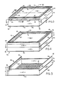
- FIGS 3-6 disclose a preferred embodiment of my invention.
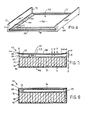
- a covered section 40 (for convenience hereafter referred to as a cassette 40) comprises a generally rectilinear boxlike, upward opening section, hereafter termed a base 42, ( Figure 5) and a cover 44 ( Figure 6). Except for non-transparent portions hereafter discussed, the base 42 and cover 44 are of a transparent or substantially transparent material and are preferably molded of a clear thermoplastic material such as food-quality clear polystyrene by a conventional molding process.
- Base 42 comprises a bottom wall 46 and opposed pairs of sidewalls 47 and 48.
- the upper surface of bottom wall 46 is provided with a conventionally contoured foundation surface 51.
- the foundation surface contour is preferably molded integrally in the upper face of the bottom wall 46 and wax coated.
- the foundation surface 51 may alternately be a conventional molded wax foundation sheet laid atop a flat upper surfaced bottom wall 46, although this has greater manufacturing cost and is thus less preferred.
- the foundation surface 51 is intended to act in a conventional manner to induce bees to build and fill comb atop thereof.
- the underside of the bottom wall 46 is flat.
- the cover 44 ( Figures 4 and 6) comprises a top wall 53 and an opposed pair of depending sidewalls 54. The remaining two sides of the cover are open, i.e. devoid of sidewalls.
- the base sidewalls 47 are shorter in height than base sidewalls 48.
- the length and width (side-to-side) dimensions of the base 42 and cover 44 are related so that the cover can be placed upon the base in the orientation shown in Figures 3 and 7, namely with the cover sidewalls 54 adjacent and snugly overlapping the base sidewalls 48 in a manner more fully hereafter described, and with the unwalled side edges 56 of the cover spaced above the top edges 57 of the shorter base sidewalls 47 to form a bee entry slot 59 which extends virtually the full width of each of the pair of shorter sidewalls 47.
- Each of the opposed bee entry slots 59 is bounded at the top by the top wall 53 of the cover 44 and at the bottom by the top edge 57 of corresponding base sidewall 47.
- the ends of each bee entry slot 59 are bounded by the inside surfaces of the other base sidewalls 48.
- the present invention thus eliminates the residual three-sided corner, like that generally indicated at 63 in Figure 2, formed by the sidewall segment 64 at the end of the notch 26.
- Such three-sided corners 63 at the ends of the bee entry notch 26 have at times in the past served as locations for the start of unwanted burr combs by bees, and also have tended to discourage the bees from fully filling the lower corners of the section of the cassette base below such corners 63, even when the walls of the section are of conventional opaque material such as wood.
- No such three-sided corners 63 are formed in the cassette according to the present invention since the bee entry slot 59 extends the full width of the base wall 47.
- the inventive structure tends to discourage, rather than encourage, building of burr comb by bees at the upper corner locations of the cassette.
- the height of the bevels 68 and of the upper wall portion 66 corresponds to the interior height of the sidewalls 54 of the cover 44.
- the vertical end edges of the cover sidewalls 54 have, as seen in Figure 6, narrow end flanges 71 extending a short distance inward along the side edges 56 of the cover and provided with inward facing bevels 72.
- the inward facing bevels 72 of the cover 44 and outward facing bevels 68 of the base 44 are correspondingly angled (in the embodiment shown at 45° to their corresponding sidewalls).
- All four bevels 72 and all four bevels 68 are located at the corners of a square, to permit the cover 44 to be dropped snugly down over the upper portion of the base 42, in both the Figure 3 or Figure 4 position thereof, with the beveled cover surfaces 72 sliding downward in snugly facing contact along the bevels 68 at the base 42.
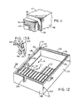
- the cassette 40 is constructed so that with the cover 44 installed on the base 42 in its in-hive position of Figure 3, the exterior surfaces of the cover side 54 is flush with the base side 48. As seen in Figure 12, this provides the important advantage that no gaps, capable of having burr comb inserted by bees, are present between the cassettes of adjacent cassette columns in a super.
- the bottom portion 74 of the base sidewalls 48 is made thicker than the upper portion 66 thereof, leaving an upward facing ledge 76 atop the bottom portion 74 outside the bottom of the upper portion 66.
- the cover sidewall 54 and ledge 76 are of the same width. Accordingly, with the cover 44 in its hive position of Figures 3 and 9 on base 42, the exterior surfaces of the cover sidewall 54 and the lower portion 74 of base sidewall 48 are flush.
- the interior height of the cover sidewalls 54 and the height of the base sidewall upper portions 66 are preferably substantially identical such that the lower edge of the cover sidewall 54 seats upon ledge 76 with the upper edge of the base sidewall upper portion 66 abutting or substantially abutting the underside of the cover top wall 53.
- the bottom of cover top wall 53 is bordered by, immediately inboard of sidewalls 54 and directly beneath side edges 56, a planar border face 77 ( Figures 6 and 7).
- the border face 77 is of sufficient width to sit flush atop the upper portion 66 of the base sidewall 48 with the cover 44 in both its Figure 3 hive position and Figure 4 marketing position on the base.
- the exterior width of the base 42 at the outside of its sidewalls 47 is the same as at the outside of the upper portions 66 of its sidewalls 48. This enables the cover to slide over, with its sidewalls 54, both the base sidewalls 47 and upper portions 66 for shifting of the cover 44 from its Figure 3 hive position to its Figure 4 marketing position.
- the lower portion of the base sidewalls 47 may be provided with widened lower portions and facing ledges corresponding to the base sidewalls 48 at 74 and 76.
- the outer face of base wall 47 is flush.
- the sidewalls 54 of the cover 44 in the marketing position of the latter, jut out, to the extent of their thickness, beyond the outer face of base sidewalls 47.
- the upward facing ledges 76 of remaining base sidewalls 48 are exposed.
- the cassette base 42 and cover 44 include a complementary ridge and stepped ledge arrangement. This locks adjacent cassettes in a column Cl or C2 of stacked cassettes against falling out the open bottom of a super of the type hereafter discussed with respect to Figures 12 and 13.
- the cover 44 has an upstanding ridge 81 ( Figures 3 and 7) atop each of the side edges 56.
- the ledge 86 preferably extends around the entire perimeter of the base 42 and hence is found at the bottom of the sidewalls 47 as well as the sidewalls 48.
- the cross-sectional height and width of the ridges 81 and ledge 86 correspond as does their separation across the width of the cassette 40.
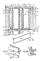
- the cassettes 40 in both their Figure 3 and Figure 4 states, are stackable in a nested manner, with the bottom of the base of one atop the top of the cover of the next to form a column, such as the column Cl in Figures 12 and 13, wherein the ridges 81 ( Figure 13) of the cover of one cassette 40B nest against the ledge 86 of the next cassette 40A in the column Cl.
- the top (facing leftward in Figure 13A) of the ridge 81 of cassette 40B fits snugly against the underside (facing right in Figure 13A) of the ledge 86 of adjacent cassette 40A so as to provide a flush connection, without significant opening, along the outer surfaces of the ridge 81 and adjacent cassette base sidewall 47.
- the height of the ridge 81 may be slightly greater than that of the ledge 86, so as to provide a small clearance between the bottom 46 of cassette 40A and the opposed top surface of the cover 44 of adjacent cassette 40B.
- the ability of cassettes 40A and 40B to thus relatively slide sideways is not a problem with the cassettes in the hive because a sufficient number of columns Cl, C2, etc. of cassettes will normally be provided in a given super to fill same, leaving no room for cassettes 40A and 40B to so relatively slide along the length direction of the ridges 81.
- ledge 86 extends around all four sides of the base 42, one contemplated alternative is providing ridges 81 on all four sides of the cassette cover, to enable the cover to mechanically lock into the ledges 86 of a cassette stacked thereon and prevent any relative movement therebetween in a plane parallel to the cassette bottom 46.
- the resulting additional pair of ridges atop cover sidewalls 54 would interfere with support of the cover of the top cassette 40A in the super of Figures 12 and 13 or would complicate the construction of the latter.
- the present invention provides the ridges 81 and ledges 86 with coactive notches 91 and lugs 92 ( Figures 3, 4, 15 and 15A).
- the notches 91 are centered along the length of the ridges 81, open upwardly and open inwardly toward each other.
- the lugs 92 are centered along the length of all four ledges 86 and protrude downwardly and laterally outwardly.
- the notches 91 can extend through the entire thickness of the corresponding ridges 81 and the lugs 92 can correspondingly extend laterally outward flush with the exterior face of the corresponding sidewall 47 or 48.
- the lateral depth of the notches 91 and lugs 92 is only about half that of the ridge 81 and ledge 86 so as to provide the exterior (leftward in Figure 15A) face of the ridge 81 as an unbroken surface.
- top wall 53 of the cover 44 is dished, the major central portion of such top wall 53 being offset somewhat below its peripheral edge (toward the opposed foundation surface 51 of its corresponding base 42).
- This downwardly offset central portion 96 is bounded on each of its four sides by a narrow, upward sloping (in Figure 3) portion 97, which is generally trapezoidal in plan.
- the sloped portions 97 are in turn bounded by the narrow border face 77 ( Figure 6).
- Such dishing of the major central portion 96 of the cover top wall 53 tends to induce bees to stop building comb up from the foundation 51 ( Figure 7) when they achieve a substantially level upper comb surface 101 approximately at the bottom edge of the bee entry slot 59 (top edge 57 of the base sidewall 47). More particularly, bees require a certain minimum height at the entry slot 59 to be induced to enter the cassette 40. Further, once in the cassette, bees require a working space of a certain minimum height and will stop building comb when the top of the comb has been built up from the cassette bottom to within that minimum working height of the top of the cassette, in this instance the underside of the cover 44. Typically, the minimum working height WS within the cassette is about the same as the entry height E.
- the material of the cassette base 42 and cover 44 is preferably a transparent or semi-transparent plastic material.
- Such can be done in a variety of ways, but in the embodiment shown it is convenient to frost the surfaces in question.
- frosting either the outside surface or inside surface of a cassette wall impairs a bee in the cassette from receiving "visual" cues through such wall from outside the cassette
- frosting the inside surface additionally prevents a bee in the cassette from receiving "visual” cues due to reflection from said wall.
- both transparency and interior surface reflectivity are to be reduced, e.g. by frosting the interior surface.
- the bottom wall 46 of the cassette base 42 is frosted on the underside thereof (as indicated at 103 in Figure 11) or both sides thereof, so that the pattern of the foundation 51 and any comb (honey-filled or otherwise) built thereon in the cassette base 42 and reflections will not be visible below the cassette base, so bees tend not to build comb downward therefrom in an underlying cassette.
- peripheral edge portions of the cover are also frosted, on the lower and upper side thereof (sloped trapezoidal portions 97 of the cover 44 as seen at 104 in Figure 3 and at 104 in Figure 6), to even more strongly discourage bees "seeing" through these sloped perimetral portions 97 of the cover top wall into the bottom wall 46 of the cassette thereabove and “seeing" reflections therefrom, and thereby to further discourage bees from building burr comb downward from the upper edges of a cassette cover.
- the transparency of the sidewalls 54 and 48 is important in inducing bees to build and fill comb to full height (essentially to the bottom of the bee entry slot 59) when cassettes are arranged in the hive in a super in side-by-side abutting columns Cl, C2, etc. ( Figure 12), such that the bees tend to build and fill comb along the plane of adjacent cassette base bottom walls almost as if the side-by-side abutting cassette sidewalls 48, 54 were not there.
- cassettes 40 embodying the present invention are configured for use with conventional, commercially available hive supers of the kind shown in Figures 12 and 13 at 120.
- a conventional super 120 comprises an upwardly and downwardly open wood plank frame 121.
- the frame 121 comprises opposed side planks 123 connected at their ends by opposed end walls 124.
- Such end walls 124 have conventional upward facing ledges 126 near the top thereof which are conventionally used to pendently support conventional full width comb frames.
- the cassette of the present invention can be used with specially designed supers it is advantageous, to minimize inventory and to facilitate use with existing equipment of established beekeepers, to dimension the inventive cassettes 40 for use with such a conventional super 120.
- the cassettes 40 embodying the invention can be stacked in the centrally unsupported, non-sagging horizontal columns Cl, C2 if pressed together and vertically supported at the endmost cassettes of the column by suitable support means.
- the present invention preferably provides a pair of follower boards 128 (Figure 14) of any substantially rigid material (preferably opaque and conveniently wood plank).
- Each board 128 has opposite ends provided along its upper edge with longitudinally extending lugs 129 to be supported on the ledges 126 of the super 120 as seen in Figure 12 for pendently supporting the follower board between the end walls 124 of the super.
- each follower board 128 is undercut to form a downward facing ledge 131.
- the rightward follower board 128 is spaced from the rightward super sidewall 123 by a plurality of upstanding, laterally spaced spacers 134, conveniently narrow wood strips.
- the rightward follower board 128 is, as seen in Figure 13, additionally provided along its bottom edge with a fixed (as by nails, adhesive or any other convenient means) thin metal strip 136, which in the embodiment shown extends the full length of the rightward follower board 128 and also extends leftwardly (into the cavity of the super) a distance exceeding the depth of the ledge 86 at the bottom of a cassette 40.
- the leftward follower board 128 is resiliently spaced from the leftward super sidewall 123 by a laterally spaced plurality of upstanding leaf springs 138.
- the leaf springs 138 are conventional, extend substantially the height of the leftward follower board 128, and are compressible between the leftward follower board 128 and leftward super sidewall 123 for resiliently compressibly sandwiching between the two follower boards 128 the column Cl of cassettes 40.
- the rightward and leftward follower boards 128 are hereafter termed, respectively, the movable and fixed follower boards (though both are only frictionally fixed against lifting from the super by the loading of the springs 138 because rightward movement of the rightward follower board 128 is prevented by contact with the rigid spacers 134 whereas rightward-leftward movement of the leftward follower board 128 is resiliently permitted by the adjacent leaf springs 138.
- a column Cl of cassettes 40 (the leftwardmost two of which are indicated specifically at 40A and 40B) are stacked in a horizontal direction between the follower boards 128 in the super 120.
- the rightwardmost cassette 40J has its bottom wall 46 seated against the fixed follower board 128 and rests with its short sidewall 47, in the portion thereof near the bottom wall 46, on the projecting portion of the metal strip 136.
- the metal strip 136 thus prevents the base of the cassette 40J from sliding downward along the fixed follower board 128.
- the top of the follower board 128 is preferably flush with the ledge 86, rather than the upward facing sidewall 47 of cassette 40J, to avoid a narrow groove which bees may tend to fill with burr comb.
- the cover 44 of cassette 40J is fixed upon its base 42 in the manner above discussed with respect to Figures 3, 7 and 8, the bevels 68 and 72 ( Figures 6 and 5, respectively) preventing movement vertically in Figure 13 of the cover with respect to its base.
- the cover 44 of cassette 40A has its upper ridge 81 resting atop the leftward (movable) follower board 128. Its lower ridge 81 is received in the ledge area 131 at the bottom of the leftward follower board 128. In this manner, the leftwardmost cassette 40A is vertically supported by its cover 44, through the leftward follower board 128 on the super 120.
- the ridges 81 on cover side edges 56 fit over and under the adjacent top and bottom surfaces of the movable follower board 128 as shown in Figure 13, with the upper edges of the cover sidewalls 54 flat against the opposed flat surface of the movable follower board 128.
- the two follower boards 128 can be identical and flat. If ridges 81 were provided on all four sides of the cover 44, it would be necessary to cut vertical grooves in the face of the movable leftward follower board 128 to receive the extra ridges, an extra manufacturing operation. Such vertical grooves would not be wanted in the rightward, nonmovable follower board 128 because the latter grooves would be unoccupied in the hive and would thus invite filling with unwanted propolis by bees.
- the cassettes of column Cl between the endmost cassettes 40A and 40J are pressed together by the compressed springs 138 and are precluded from sliding downward out the open bottom 141 of the super 120 by horizontal overlapping of the ridges 81 of the intermediate covers 44 with the ledges 86 in the base 42 of each adjacent cassette base 40.
- the horizontal column Cl is rigid and fixed and will not bend or drop through the open bottom the super 120 despite lack of underlying transverse slats.
- the absence of slats in super 120 advantageously facilitates cassette filling by allowing visual cues to bees in a cassette from bee activity therebeneath in the hive.
- follower boards 128 which are opaque advantageously further block visual cues to bees in endmost cassettes 40A and 40J in column Cl from bee activity in passages 146 and 147 respectively.
- Hives In conventional hives, a series of supers are stacked one atop the other with communicating openings so that bees may travel upward and downward from super to super.
- several supers 120 equipped with cassettes 40 as above described, when in the hive may be stacked, for example as at 120 and 120' in Figure 13.
- Parts associated with super 120' carry the same reference numerals as those associated with super 120, but with a prime mark (') added.
- Hives are conventionally provided with a hive cover and a hive base (not shown) which respectively overlie and underlie the vertical stack of supers.
- Conventional hive covers and/or hive bases provided bee access from the outside atmosphere to the adjacent open top or bottom end of the adjacent super. Such is conventional and well known and needs no further description or showing.
- the column Cl at the left end of the pack in Figure 12 and the column (not shown) at the rightward end of the pack are spaced from the respective left and right super end walls 124 by spaces 145 which serve as bee passages. Bee activity in such spaces 145 can visually cue bees in adjacent cassettes.
- the spaces 145 are preferably of width equal to the standard Langstroth bee space (about 5/16 inch) to deter comb building in spaces 145.
- a room 149 of height R sufficient for lateral bee travel is formed between the cassettes of each pair of adjacent stacked supers, e.g. supers 120 and 120' of Figure 13.
- the room 149 extends laterally through the full interior width and length of the adjacent supers and is accessible from the passages 146 and 147 of both supers.
- Each cassette bounding such room 149 has one of its bee entry slots 59 opening into such room 149.
- bees can travel vertically in the hive through the cassettes 40 and passages 145, 146 and 147 or any combination thereof as linked by the horizontally extending rooms 149.
- passages 146 and 147 and rooms 149 like spaces 145, is large enough to permit bee travel and is kept small enough (bees will not violate the classical Langstroth "bee space" of 1/4" to 3/8" and more exactly 9/32") so as not to induce bees to build burr comb therein, even despite transparency of cassette short sidewalls 47 at the top and bottom of the rooms 149.
- transparency of the cassette sidewalls provides visibility of bee activity in the spaces 145 and the room 149 between cassette cavities in supers 120 and 120' to promote uniform filling of such cavities.
- the leaf springs 138 can be slid lengthwise, while compressively flexed, into their position between the movable follower board 128 and adjacent super sidewall 123 to compressively urge together the cassettes 40 of each of the columns Cl, C2, etc. and to urge such columns against the fixed follower board 128 and spacers 134.
- the super 120 can be returned 90° back through the angle AA to its Figure 13 position wherein the now horizontal pressure of the leaf springs 138 on the cassettes and interlocking ridges 81 and ledges 86 of the cassettes enables the follower boards 128 to fixedly locate the cassette stacks Cl, C2, etc. vertically with respect to the open top and bottom of the super, as seen in Figure 13.
- bees After assembly of a hive from a plurality of stacked supers 120, and conventional hive base and roof elements not shown, bees are permitted to enter the hive through conventional hive entries not shown and move upwardly and downwardly from super to super through the passages 146 and 147 ( Figure 13), and horizontally through the horizontally open rooms 149 between cassette columns of adjacent supers, and vertically into and through the bee entry slots 59 which, as shown in Figure 13, are preferably vertically aligned from super to super.
- bees have free access to each cassette to build comb on the foundation 51 thereof and to fill same with honey.
- cassettes After being in the hive for a period of time, cassettes can be readily inspected to determine if they are filled. More particularly, a quick visual inspection can be carried out on the hive merely by looking through the transparent sidewalls 47 of the various cassettes in a given super. A good idea of the extent of fill can be obtained without need to remove supers from the hive.
- the cassettes 40 can be removed from the super 120 substantially by reversing the steps of installation. More particularly, a super 120 is removed from the hive and rotated through the angle AA in Figure 13 so that the cassette columns Cl, C2, etc. are upstanding. Then, the springs 138 are removed from between the movable follower board 128 atop the cassette columns and the opposed super sidewall 123. The fixed (in this position lower) follower board 128 can be pulled, like a kind of tray, laterally out of the now rightwardly facing open top of the super while supporting thereon all of the upstanding cassette columns Cl, C2, etc. and topped by the movable follower board 128.
- the cassettes in the individual columns can be unstacked. If some cassettes are unfinished, they can be accumulated and repacked easily (partial harvesting) or whole columns can be interchanged and the super replaced in the hive to encourage uniform filling, according to observed needs.
- each finished cassette can then be removed, rotated through 90°, and replaced upon the base 42 of such cassette, to place the cassette in its marketing configuration of Figure 4, wherein the bee entry slots 59 are closed, and the cassette as a whole indeed is closed.
- Suitable labeling can be applied to any desired outer surfaces of the cassette and the cover can be secured to the base, as by means of tape, adhesive labels, or any other convenient means, so as to inhibit opening of the cassette until the retail purchaser takes it home and is ready to use it.
- the cassettes in their Figure 4 marketing configuration are readily stackable one atop the other in stacks made laterally stable by intermeshing of the ridges 81 with the ledges 86 and of the lugs 92 with the notches 91.
- the cassettes 40 advantageously incorporate means for stacking cassettes into horizontal columns which are self-supporting in a super, thus eliminating need for underlying wood slats which would block visual cues through cassette sides supported by such slats.
- the ridge 81 and ledge 86 make a laterally extending columnar stack of cassettes self-supporting intermediate its ends and facilitates the support of the ends of the columnar stack within the super, given the compressive force of the springs 138.
- the present invention advantageously extends the bee entry slots 59 to the full width of the cassette 40 while still permitting rotating the cover 44 from its Figure 3 hive position to its Figure 4 marketing position.
- the coacting bevels at 68 and 72 Figure 9) prevent lateral displacement of the cover 44 with respect to the base 42 and eliminate the need for protrusions extending downward from the cover (or from an adjacent cassette bottom as in Figure 2) into the upper portion of the base cavity and thereby further discourage "corner” burr, to thereby encourage fully filling the corners of the cassette base therebelow with honey comb.
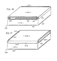
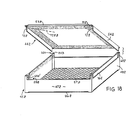
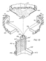
- the modified Figure 16-19 embodiment is preferably similar to the abovedescribed Figure 3-15A embodiment except for differences described below. Parts in the modified Figure 16-18 embodiment corresponding to parts in the abovedescribed Figure 3-15A embodiment will be referred to by the same reference numerals with the suffix "Z" added.
- the cover sidewall 54 is shorter in horizontal extent than the cover top wall 53Z and the base sidewalls 47Z and 48Z, so as to end at a distance from the corners of the cover top wall 53Z.
- the ends of the cover sidewalls 54Z are beveled at 72Z and these beveled end surfaces 72Z each lie in a corresponding imaginary vertical plane (one being indicated by the dotted line 72ZZ) extending through the generally central portion (not necessarily the actual center) of the cover top wall 53Z.
- each beveled surface 72Z faces both inward toward the opposite sidewall 54Z and toward the immediately adjacent corner of the cover top wall 53Z.
- the bevels 72Z are thus angled approximately a quarter turn from the beveled surfaces 72 of the Figure 6 embodiment.
- the base 42 at each end of the base sidewall 48Z has an upper corner structure 201 separating the ends of the adjacent bee entry slot 59Z and recessed upper sidewall portion 66Z and carrying upstanding beveled surfaces 68Z and 68Z' terminating the ends of the adjacent recessed upper sidewall portion 66Z and-the bee entry slot 59Z.
- the beveled surfaces 68Z and 68Z' though not necessarily parallel, do face generally opposite each other. More particularly, the beveled surface 68Z faces angularly outward from the base and toward the opposite end of the corresponding recessed upper sidewall portion 66Z.
- the beveled surface 68Z' faces angularly outward of the cassette base and toward the opposite end of the corresponding bee entry slot 59Z.
- the angle of the base beveled surfaces 68Z and 68Z' match that of the cover sidewalls end surfaces 72Z so that the cover beveled surfaces 72Z rest close to and substantially parallel with the base beveled surfaces 68Z and 68Z' respectively in the Figure 16 and Figure 17 cover positions on the base.
- cover sidewalls are shallower, thicker and recessed in the base sidewalls (and thus protected from breakage e.g. by the apiarist's scraping tool when cleaning cassettes). Also, the "marketing" position overlap of cover and base sidewall is eliminated, the sidewalls of the base and cover being flush both in the "hive” and “marketing” positions, for more compact packing and shipping cartons, for greater stability when displayed on edge and to provide broader flat surfaces to carry labels. Also, recessing of the ends of the cover sidewalls reduces the amount of cracks in the cassette accessible to bees and hence reduces "crack" cues tending to induce construction of burr comb.
- the ridges 81Z and ledges 86Z need not run the entire length of the corresponding cassette cover and base side edges but may instead end a short distance from the corners of the cassette. In this way, the ends of the ridges 81Z of the cover of one cassette will be recessed in and protected by the ends of the corresponding sidewall 47Z or 48Z of the base of a cassette stacked thereatop.
- the cover top wall 53Z in Figures 16-19 is made flat, rendering it more easily cleanable.
- the visual cues provided by cassette base construction below the bee entry slot and elimination of visual cues above the height of the bee entry slot on the base sidewalls 48Z are relied on to induce comb building and filling up to the height of the bee entry slot and not above, so as to provide a substantially level filled comb in the cassette.
- the cassette bases 42Z may, as an alternative, be stacked top-to-bottom (like Figure 2A bases or sections 20A, 20B) to form columns analogous to those at Cl, C2 in Figure 2, and without their covers 44Z.
- the beekeeper is given a particularly advantageous flexibility if, using the same type of cassette, he can alternately, as desired, make columnar stacks in the hive of cassette bases only (arranged top-to-bottom as in Figure 2A) or complete cassettes (covers and bases) as in Figure 12. It is further desirable to provide such flexibility without generating further cracks or corners to cue bees to build burr comb (to avoid the protrusions 33 of Figure 2A for example).
- the cassette cover 44Z has similar holes 207 adjacent the corners of the bottom face of the top wall 53Z thereof arranged in aligned relation to receive the post 203 therein with the cover in its Figure 16 and Figure 17 positions on the base. Also, snug registration of the posts 203 in the holes 207 in the cover helps frictionally hold the cover from lifting off the base when separating cassettes from a column and assists in lateral location of the cover on the base.
- a columnar stack of cassette bases 42Z with its holes 205 and posts 203 and without interposed covers may be located with a single cover 44Z on the base 42Z whose top faces one of the follower boards 128 of Figure 12, to positively locate thereon the end of the columnar stack of such cassette bases.
- the modified Figure 16-19 embodiment also permits the beekeeper the further alternative of use of entire (covered) cassettes in the hive with covers that are not marketed with the filled cassette base but rather are removed and replaced with clean covers for marketing, the used covers being applied to new cassette bases for filling with honey in the next cycle of hive operation. In this way, if minor amounts of burr comb accumulate on the covers in the hive, any risk of that burr comb detracting from the marketing appearance of the cassette can be avoided.
- this capability will be needed, since the risk of significant burr comb accumulation has been substantially reduced and ease of cleaning has been enhanced.
Landscapes
- Life Sciences & Earth Sciences (AREA)
- Environmental Sciences (AREA)
- Animal Husbandry (AREA)
- Biodiversity & Conservation Biology (AREA)
- Packaging Of Annular Or Rod-Shaped Articles, Wearing Apparel, Cassettes, Or The Like (AREA)
- Fencing (AREA)
- Jellies, Jams, And Syrups (AREA)
- Meat, Egg Or Seafood Products (AREA)
Applications Claiming Priority (4)
| Application Number | Priority Date | Filing Date | Title |
|---|---|---|---|
| US58176284A | 1984-02-21 | 1984-02-21 | |
| US581762 | 1984-02-21 | ||
| US687314 | 1984-12-28 | ||
| US06/687,314 US4639962A (en) | 1984-02-21 | 1984-12-28 | Apparatus for comb honey |
Publications (2)
| Publication Number | Publication Date |
|---|---|
| EP0152850A2 true EP0152850A2 (de) | 1985-08-28 |
| EP0152850A3 EP0152850A3 (de) | 1987-04-01 |
Family
ID=27078416
Family Applications (1)
| Application Number | Title | Priority Date | Filing Date |
|---|---|---|---|
| EP85101149A Withdrawn EP0152850A3 (de) | 1984-02-21 | 1985-02-04 | Gerät zur Gewinnung von Wabenhonig |
Country Status (5)
| Country | Link |
|---|---|
| US (1) | US4639962A (de) |
| EP (1) | EP0152850A3 (de) |
| AU (1) | AU576995B2 (de) |
| CA (1) | CA1234316A (de) |
| NZ (1) | NZ211001A (de) |
Cited By (7)
| Publication number | Priority date | Publication date | Assignee | Title |
|---|---|---|---|---|
| KR20030058499A (ko) * | 2001-12-31 | 2003-07-07 | 류무열 | 소밀생산용 벌통 |
| CN102783430A (zh) * | 2012-04-23 | 2012-11-21 | 崔成林 | 零售量筒状包装物及原生在筒内蜂巢蜜的生产方法和生产装置 |
| WO2018103149A1 (zh) * | 2016-12-10 | 2018-06-14 | 北京市蜂业公司 | 一种巢蜜的生产方法 |
| WO2021116454A1 (fr) * | 2019-12-13 | 2021-06-17 | Oudin Charles Olivier | Dosette à miel à placer dans une ruche permettant une extraction par pressage du miel |
| FR3125677A1 (fr) * | 2021-07-28 | 2023-02-03 | Bee's Dream | Pressoir a miel, dosette de miel, systeme d’extraction de miel |
| EP4292428A1 (de) * | 2022-06-15 | 2023-12-20 | Korpikuusikon Hunaja Oy | Wabenkassette, basis einer wabenkassette, verfahren zum produzieren der wabenkassette, bienenstock und verfahren zum produzieren von wabenhonig |
| DE102025105023B3 (de) * | 2025-02-11 | 2025-12-31 | Bienen Janisch GmbH | Anordnung zur Produktion von Wabenhonig |
Families Citing this family (9)
| Publication number | Priority date | Publication date | Assignee | Title |
|---|---|---|---|---|
| DE69524307T2 (de) * | 1994-08-12 | 2002-08-08 | Hewlett-Packard Co.(A Delaware Corporation), Palo Alto | Kappenausrichtung und Wischerpositionierung zur Reinigung eines Tintenstrahldruckers |
| US6746305B2 (en) * | 2002-02-25 | 2004-06-08 | Bela Malacsina | Honey packaging and method |
| EP1581048A2 (de) * | 2002-12-13 | 2005-10-05 | 6116469 Canada Inc. | Vorrichtung zur gewinnung von wabenhonig |
| US9485968B2 (en) | 2011-10-28 | 2016-11-08 | Carl Jackson | Beehive system |
| US9119382B2 (en) * | 2013-02-26 | 2015-09-01 | Tyson Foods Inc. | Portable basket colony for growing and transport and method of use |
| US20170332608A1 (en) * | 2016-05-19 | 2017-11-23 | PAC Basic, LLC | Top Bar Nucleus Hive |
| US11375697B2 (en) | 2017-04-12 | 2022-07-05 | Alessandro GAMBERONI | Rational hive structure |
| FI12806Y1 (fi) * | 2020-01-09 | 2020-10-22 | Paradise Honey Oy | Hunajakennostokehän rakenne |
| US20240334914A1 (en) * | 2023-04-08 | 2024-10-10 | James Milton Romano | Honeybee frame comb maker |
Family Cites Families (30)
| Publication number | Priority date | Publication date | Assignee | Title |
|---|---|---|---|---|
| US302854A (en) * | 1884-07-29 | Bee-hive | ||
| US31658A (en) * | 1861-03-12 | Beehive | ||
| US452366A (en) * | 1891-05-19 | Bee-hive | ||
| US337143A (en) * | 1886-03-02 | Honey-box case and clamp | ||
| US529116A (en) * | 1894-11-13 | Super for beehives | ||
| US243674A (en) * | 1881-06-28 | Sectional honey-frame | ||
| US338647A (en) * | 1886-03-23 | Bee-hive | ||
| FR958111A (de) * | 1950-03-03 | |||
| US154874A (en) * | 1874-09-08 | Improvement in bee-hives | ||
| US86913A (en) * | 1869-02-16 | Garret j | ||
| US427993A (en) * | 1890-05-13 | Bee-hive | ||
| US804736A (en) * | 1904-06-07 | 1905-11-14 | George F Kregel | Beehive. |
| US846396A (en) * | 1906-03-05 | 1907-03-05 | Ai Root Co | Beehive-frame. |
| US869917A (en) * | 1907-03-18 | 1907-11-05 | Walter J Lewis | Comb-honey section. |
| US929616A (en) * | 1909-01-27 | 1909-07-27 | George W Maxwell | Honey-box section. |
| US993551A (en) * | 1910-07-05 | 1911-05-30 | Albert Rogers | Beehive. |
| US995070A (en) * | 1910-12-02 | 1911-06-13 | Lars M Linblom | Super for beehives. |
| US1042907A (en) * | 1912-03-05 | 1912-10-29 | James A Gebhart | Beehive. |
| US1637002A (en) * | 1923-11-12 | 1927-07-26 | Koepp Herman | Spacing arrangement of bee frames |
| US2023959A (en) * | 1933-11-04 | 1935-12-10 | Knox James Frank | Beehive |
| US2604643A (en) * | 1947-06-11 | 1952-07-29 | Edward C Wheaton | Beehive honeycomb frame |
| DE814966C (de) * | 1949-03-04 | 1951-09-27 | Johann Thuer | Bienenwohnung |
| US3088135A (en) * | 1961-08-10 | 1963-05-07 | William Z Covington | Frame and plastic comb foundation for beehives |
| US3187353A (en) * | 1964-02-10 | 1965-06-08 | Willis L Ackerman | Comb honey frame |
| DE2028914A1 (de) * | 1970-06-12 | 1971-12-16 | Kachelmann, Andreas, 8600 Bamberg | Einteilige Waben für die Bienenzucht |
| AT348821B (de) * | 1976-04-20 | 1979-03-12 | Matthaeus Dipl Ing Krasnik | Vorrichtung zur gewinnung von waben-bzw. scheibenhonig |
| US4195379A (en) * | 1977-09-21 | 1980-04-01 | Matthaus Krasnik | Device for collecting honey and comb honey package |
| GB2023395B (en) * | 1978-06-19 | 1982-06-09 | Green A E A | Beehives |
| US4329749A (en) * | 1980-02-13 | 1982-05-18 | Hogg John A | Frame for comb honey |
| US4435865A (en) * | 1980-02-13 | 1984-03-13 | Hogg John A | Frame for comb honey |
-
1984
- 1984-12-28 US US06/687,314 patent/US4639962A/en not_active Expired - Lifetime
-
1985
- 1985-01-30 AU AU38188/85A patent/AU576995B2/en not_active Ceased
- 1985-01-31 CA CA000473266A patent/CA1234316A/en not_active Expired
- 1985-01-31 NZ NZ211001A patent/NZ211001A/en unknown
- 1985-02-04 EP EP85101149A patent/EP0152850A3/de not_active Withdrawn
Cited By (10)
| Publication number | Priority date | Publication date | Assignee | Title |
|---|---|---|---|---|
| KR20030058499A (ko) * | 2001-12-31 | 2003-07-07 | 류무열 | 소밀생산용 벌통 |
| CN102783430A (zh) * | 2012-04-23 | 2012-11-21 | 崔成林 | 零售量筒状包装物及原生在筒内蜂巢蜜的生产方法和生产装置 |
| WO2018103149A1 (zh) * | 2016-12-10 | 2018-06-14 | 北京市蜂业公司 | 一种巢蜜的生产方法 |
| US10736345B2 (en) | 2016-12-10 | 2020-08-11 | Beijing Apiculture Company | Production method for comb honey |
| WO2021116454A1 (fr) * | 2019-12-13 | 2021-06-17 | Oudin Charles Olivier | Dosette à miel à placer dans une ruche permettant une extraction par pressage du miel |
| FR3104377A1 (fr) * | 2019-12-13 | 2021-06-18 | Charles-Olivier OUDIN | Dosette à miel à placer dans une ruche permettant une extraction par pressage du miel |
| FR3125677A1 (fr) * | 2021-07-28 | 2023-02-03 | Bee's Dream | Pressoir a miel, dosette de miel, systeme d’extraction de miel |
| EP4292428A1 (de) * | 2022-06-15 | 2023-12-20 | Korpikuusikon Hunaja Oy | Wabenkassette, basis einer wabenkassette, verfahren zum produzieren der wabenkassette, bienenstock und verfahren zum produzieren von wabenhonig |
| DE102025105023B3 (de) * | 2025-02-11 | 2025-12-31 | Bienen Janisch GmbH | Anordnung zur Produktion von Wabenhonig |
| EP4789537A1 (de) | 2025-02-11 | 2026-08-12 | Eggert, Lutz | Anordnung zur produktion von wabenhonig |
Also Published As
| Publication number | Publication date |
|---|---|
| NZ211001A (en) | 1988-01-08 |
| EP0152850A3 (de) | 1987-04-01 |
| CA1234316A (en) | 1988-03-22 |
| US4639962A (en) | 1987-02-03 |
| AU576995B2 (en) | 1988-09-08 |
| AU3818885A (en) | 1985-08-29 |
Similar Documents
| Publication | Publication Date | Title |
|---|---|---|
| US4639962A (en) | Apparatus for comb honey | |
| CA1269247A (en) | Interlocking container and toy block sets | |
| SE9101862A0 (sv) | Dispenser för medicinska preparat | |
| US3941247A (en) | Modular display means | |
| US4175807A (en) | Modular constructional units for a combined storage bin and display assembly | |
| US4435865A (en) | Frame for comb honey | |
| CA1247458A (en) | Method and cover board for harvesting honey in free beekeeping | |
| US4329749A (en) | Frame for comb honey | |
| US4133065A (en) | Modular beehive construction and component therefor | |
| US4250837A (en) | Poultry nest bank unit | |
| US6606965B2 (en) | Stackable pet shelter | |
| US2023959A (en) | Beehive | |
| US5035668A (en) | Beehive | |
| US3529879A (en) | Modular construction for storage cabinet | |
| CN217160796U (zh) | 一种可叠加的全包围式巢蜜框 | |
| EP1288137A2 (de) | Verpackung zum Aufnehmen schindelartig angeordneter scheibenförmig ausgebildeter Lebensmittel | |
| WO2002076194A1 (en) | A new beehive | |
| US20250223101A1 (en) | Double chamber honey packaging | |
| RU2134959C1 (ru) | Бесфальцевый многокорпусный улей с магазинами | |
| AU2007200234A1 (en) | Improvement in production of honey comb | |
| US20260096536A1 (en) | Pet litter tray | |
| WO1991007328A1 (en) | Improvements in storage crates | |
| US20030213438A1 (en) | Stack of nested shelter components | |
| JPS6041842Y2 (ja) | コンパクト | |
| US384627A (en) | Bee-hive |
Legal Events
| Date | Code | Title | Description |
|---|---|---|---|
| PUAI | Public reference made under article 153(3) epc to a published international application that has entered the european phase |
Free format text: ORIGINAL CODE: 0009012 |
|
| AK | Designated contracting states |
Designated state(s): DE FR GB IT |
|
| PUAL | Search report despatched |
Free format text: ORIGINAL CODE: 0009013 |
|
| AK | Designated contracting states |
Kind code of ref document: A3 Designated state(s): DE FR GB IT |
|
| STAA | Information on the status of an ep patent application or granted ep patent |
Free format text: STATUS: THE APPLICATION IS DEEMED TO BE WITHDRAWN |
|
| 18D | Application deemed to be withdrawn |
Effective date: 19871002 |