EP0152147A2 - Elastische Magnetklemme - Google Patents
Elastische Magnetklemme Download PDFInfo
- Publication number
- EP0152147A2 EP0152147A2 EP85200156A EP85200156A EP0152147A2 EP 0152147 A2 EP0152147 A2 EP 0152147A2 EP 85200156 A EP85200156 A EP 85200156A EP 85200156 A EP85200156 A EP 85200156A EP 0152147 A2 EP0152147 A2 EP 0152147A2
- Authority
- EP
- European Patent Office
- Prior art keywords
- strips
- panels
- clamp
- panel
- edge
- Prior art date
- Legal status (The legal status is an assumption and is not a legal conclusion. Google has not performed a legal analysis and makes no representation as to the accuracy of the status listed.)
- Granted
Links
Images
Classifications
-
- G—PHYSICS
- G09—EDUCATION; CRYPTOGRAPHY; DISPLAY; ADVERTISING; SEALS
- G09F—DISPLAYING; ADVERTISING; SIGNS; LABELS OR NAME-PLATES; SEALS
- G09F1/00—Cardboard or like show-cards of foldable or flexible material
- G09F1/10—Supports or holders for show-cards
-
- A—HUMAN NECESSITIES
- A47—FURNITURE; DOMESTIC ARTICLES OR APPLIANCES; COFFEE MILLS; SPICE MILLS; SUCTION CLEANERS IN GENERAL
- A47G—HOUSEHOLD OR TABLE EQUIPMENT
- A47G1/00—Mirrors; Picture frames or the like, e.g. provided with heating, lighting or ventilating means
- A47G1/16—Devices for hanging or supporting pictures, mirrors, or the like
- A47G1/17—Devices for hanging or supporting pictures, mirrors, or the like using adhesives, suction or magnetism
-
- B—PERFORMING OPERATIONS; TRANSPORTING
- B42—BOOKBINDING; ALBUMS; FILES; SPECIAL PRINTED MATTER
- B42F—SHEETS TEMPORARILY ATTACHED TOGETHER; FILING APPLIANCES; FILE CARDS; INDEXING
- B42F9/00—Filing appliances with devices clamping file edges; Covers with clamping backs
Definitions
- the present invention relates to a magnetic clamp having clamping faces, each including a flexible synthetic plastics foil panel with embedded parallel strips of magnetic material, said strips having alternating polarities, and said panels being interconnected for -movement between an open position and a clamping position in such a manner that in the clamping position, opposite strips of magnetic material have opposite polarities.
- Such a clamp is described in US patent 4,258,493 and comprises a flexible backing band to which the panels with embedded magnetic strips are secured in spaced relationship.
- the intermediate portion of the backing band is bent to a U-shape for opposing the two panels, thereby enclosing an object to be fixed.
- the mutual magnetic attraction of the two panels will then ensure sufficient surface pressure on the clamped object so as to prevent the object from slipping out of the clamp to an extent sufficient for normal use.
- clamping effect of such a flexible magnetic clamp is relatively substantial, since, in contrast to non-flexible mechanical clamps, the clamping force is not exerted on the panels by a separate force-applying means, such as a spring, but the clamping force is produced in the material proper, and this throughout the entire surface of the two panels.
- a drawback of the device disclosed in US patent 4,258,493 is that it is always necessary to take care that the panels lie in the proper relative opposite positions. Even a slight relative displacement transverse to the longitudinal direction of the magnetized strips, which is possible owing to the flexibility of the backing band, may cause magnetized strips of equal polarity to become opposed, so that the clamping faces repel instead of attract each other.
- Another drawback of the use of a backing band is that no optimum use can be made of the flexibility of the synthetic plastics foil panels, for, if only because of its greater thickness, the assembly of panel and backing band is less flexible than a flexible panel alone.
- the foil panels of the clamp according to the present invention have a fixed relative position by being locally attached to each other. No use is made of a backing band.
- the foil panels proper form the clamping faces of the clamp and can be provided at their distal sides directly with a print and/or an adhesive layer for attachment of the clamp to a wall and the like.
- the flexible magnetic clamp may comprise two substantially equally large foil panels fixed along one edge relatively to one another, the strips of magnetized material extending substantially at right angles to the fixed edge.
- the clamp Since in the clamp according to the present invention, the panels are locally interconnected, the clamp has a paperclip effect, i.e. when either panel is lifted the interspace tapers in the direction of the fixed edge, so that the edge of an object pushed into the clamp can already be clamped in the narrow portion.
- the opened clamp is released the bent portions will move towards each other initially exclusively under the influence of the resiliency inherent in the synthetic plastics material until the facing sides of the panels have approached each other so closely that the respective magnetic fields influence each other, thereby closing the clamp visibly faster.
- the clamps according to the present invention may be very thin, i.e. in the order of 1.5 mm, and be made self-adhesive in a simple manner and moreover are resistant to moisture and corrosion, they are excellently suitable for fixing temporarily, even on uneven surfaces, various paper articles, such as memorandums, drafts, window bills, posters, notices and the like in shops, stores, offices, motor-cars, caravans and the like.
- clamps may be made in various foil thicknesses, thicker foils being adapted to contain more magnetizable material, and hence to exert a greater clamping force per unit of surface area.
- the two panels constituting the clamp may be locally fixed relatively to each other, thereby enclosing an abutment forming a contacting edge, said abutment having a thickness in the order of that of the material for which the clamp is designed.
- the abutment moreover facilitates the positioning of an article in such a clamp.
- a particular application of the present invention is a map or chart holder comprising a lower panel and a flexible, transparent upper panel connected at one edge by a clamp according to the present invention and being each provided at the opposite edge with coacting bandsof flexible foil with embedded strips of magnetized material, the polarities alternating in the successive strips.
- a leaf-shaped article such as a map or sea chart, can be interposed between the panels and since the alternating polarities of the opposite strips of magnetized material prevent any shift of the upper panel relatively to the lower panel, the transparent upper panel is always retained in tight condition over the map.
- the upper panel may consist of material on which can be written, such as polycarbonate or transparent polystyrene in matted design, allowing notes to be made and positions to be indicated on a clamped map or chart without the risk of navigation errors as a result of a shift of the map or chart underneath the upper panel.
- Panels 1, 2 are made of a flexible synthetic plastics material, e.g. modified polyethylene, and have embedded therein, at an interspace of e.g. 2 mm, strips 3, 4 of magnetizable material such as barium ferrite or strontium ferrite.
- each strip 3 of the panel 2 is opposed to a magnetic strip 4 in the panel 1 and vice versa.
- the visible surface of the clamp may be coated with a vinyl layer in any color desired and may, at choice be provided with text or representations.
- the abutment 13 may be formed by an adhesive layer whose thickness is chosen to suit the contemplated use of the clamp, i.e. in the order of the thickness of the material to be clamped therein, so that when the material is clamped between them, the panels 1, 2 extend as much as possible in mutually parallel relationship, ensuring an optimum clamping effect.
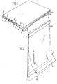
- Fig. 2 shows a map or chart holder having a rigid lower panel 5 and a flexible upper panel 6. Panels 5, 6 are hinged together at one of their edges and in the position shown, two opposite edges are provided with magnetic foil bands 7, 8 and 9,10, respectively.
- a clamped sheet 11, e.g. a map, is pushed between panels 5, 6 into abutment with the hinging edge between strips 9, 10 and when the panel 6 is closed over the panel 5, the map 11 is affixed at two edges, while also the flexible panel 6 is kept tight on the rigid panel 5.
- Fig. 2 does not show the magnetized strips in the bands 7-10. It is observed that the strips need not necessarily extend at right angles to the hinge. It is necessary though that they extend in mutually parallel relationship per panel or band, and that the strips of coacting panels in closed clamping position lie directly opposite each other and have opposite magnetic polarities.
Landscapes
- Physics & Mathematics (AREA)
- General Physics & Mathematics (AREA)
- Engineering & Computer Science (AREA)
- Theoretical Computer Science (AREA)
- Sheet Holders (AREA)
Applications Claiming Priority (2)
| Application Number | Priority Date | Filing Date | Title |
|---|---|---|---|
| NL8400431A NL187040C (nl) | 1984-02-10 | 1984-02-10 | Flexibele magnetische klem en kaarthouder voorzien van een dergelijke klem. |
| NL8400431 | 1984-02-10 |
Publications (3)
| Publication Number | Publication Date |
|---|---|
| EP0152147A2 true EP0152147A2 (de) | 1985-08-21 |
| EP0152147A3 EP0152147A3 (en) | 1985-09-25 |
| EP0152147B1 EP0152147B1 (de) | 1991-01-16 |
Family
ID=19843470
Family Applications (1)
| Application Number | Title | Priority Date | Filing Date |
|---|---|---|---|
| EP19850200156 Expired EP0152147B1 (de) | 1984-02-10 | 1985-02-08 | Elastische Magnetklemme |
Country Status (3)
| Country | Link |
|---|---|
| EP (1) | EP0152147B1 (de) |
| DE (1) | DE3581296D1 (de) |
| NL (1) | NL187040C (de) |
Cited By (5)
| Publication number | Priority date | Publication date | Assignee | Title |
|---|---|---|---|---|
| WO1990003138A1 (en) * | 1988-09-26 | 1990-04-05 | Frank James Ross | Display device |
| FR2645421A1 (fr) * | 1989-04-06 | 1990-10-12 | Giberstein Daniel | Dispositif d'encadrement et de fixation a un support metallique de documents, de photographies ou analogues |
| WO1995033253A1 (en) * | 1994-05-30 | 1995-12-07 | Christer Zarelius | A picture or text display unit |
| ES2153316A1 (es) * | 1999-02-26 | 2001-02-16 | Jimenez Manuel Sanchez | Medios de obscurecimiento de vidrios dobles. |
| FR2929435A1 (fr) * | 2008-03-28 | 2009-10-02 | Hmy Gestion Soc Par Actions Si | Dispositif d'affichage flexible |
Family Cites Families (5)
| Publication number | Priority date | Publication date | Assignee | Title |
|---|---|---|---|---|
| FR1590570A (de) * | 1968-05-08 | 1970-04-20 | ||
| US4023290A (en) * | 1974-01-21 | 1977-05-17 | Josephson Joseph P | Chart device |
| BE832377A (fr) * | 1975-08-13 | 1975-12-01 | Element pour la suspension de cadres, gravures, peintures ou similaires | |
| US4258493A (en) * | 1979-05-04 | 1981-03-31 | Cling Cal Corporation | Advertising display means and method |
| DE8311516U1 (de) * | 1982-04-22 | 1983-09-15 | West Country Marketing & Advertising Ltd., Clifton, Bristol | Vorrichtung zum aufhaengen blattfoermigen materials |
-
1984
- 1984-02-10 NL NL8400431A patent/NL187040C/xx not_active IP Right Cessation
-
1985
- 1985-02-08 DE DE8585200156T patent/DE3581296D1/de not_active Expired - Lifetime
- 1985-02-08 EP EP19850200156 patent/EP0152147B1/de not_active Expired
Cited By (5)
| Publication number | Priority date | Publication date | Assignee | Title |
|---|---|---|---|---|
| WO1990003138A1 (en) * | 1988-09-26 | 1990-04-05 | Frank James Ross | Display device |
| FR2645421A1 (fr) * | 1989-04-06 | 1990-10-12 | Giberstein Daniel | Dispositif d'encadrement et de fixation a un support metallique de documents, de photographies ou analogues |
| WO1995033253A1 (en) * | 1994-05-30 | 1995-12-07 | Christer Zarelius | A picture or text display unit |
| ES2153316A1 (es) * | 1999-02-26 | 2001-02-16 | Jimenez Manuel Sanchez | Medios de obscurecimiento de vidrios dobles. |
| FR2929435A1 (fr) * | 2008-03-28 | 2009-10-02 | Hmy Gestion Soc Par Actions Si | Dispositif d'affichage flexible |
Also Published As
| Publication number | Publication date |
|---|---|
| DE3581296D1 (de) | 1991-02-21 |
| NL8400431A (nl) | 1985-09-02 |
| NL187040B (nl) | 1990-12-03 |
| NL187040C (nl) | 1991-05-01 |
| EP0152147B1 (de) | 1991-01-16 |
| EP0152147A3 (en) | 1985-09-25 |
Similar Documents
| Publication | Publication Date | Title |
|---|---|---|
| US4588209A (en) | Powerful magnetic folio | |
| US5103756A (en) | Magnetic placemark | |
| CA2133862C (en) | Magnetic paper clamp and method of producing same | |
| US4258493A (en) | Advertising display means and method | |
| US4605292A (en) | Mirror with adhesive/magnetic mirror supporting strips | |
| JP3811768B2 (ja) | 接着クリップ | |
| US6550812B1 (en) | Magnetic write/erase binder | |
| US5050834A (en) | Magnetically supported frame for photographic picture cards | |
| JPS62503130A (ja) | 磁気咬合装置 | |
| US4436053A (en) | Clip-on bookmark | |
| US5437428A (en) | Picture mount system | |
| US3755938A (en) | Graphmatic magnegraph | |
| GB2321418B (en) | Improvements in and relating to materials | |
| US4023290A (en) | Chart device | |
| US3596393A (en) | Device for the housing and storage of microfilm | |
| EP0152147B1 (de) | Elastische Magnetklemme | |
| ATE235379T1 (de) | Vorrichtung zum binden von blättern und zusammengebundene blätter | |
| US5396722A (en) | Picture frame members | |
| US6158597A (en) | Hangable calendar assembly | |
| CA2106240C (en) | Improved bookmark | |
| US5209624A (en) | Method of interconnecting two sheets or plates, especially a method of covering a book | |
| GB2315459A (en) | A bookmark | |
| GB2315705A (en) | Magnetic bookmark | |
| JPH0425751Y2 (de) | ||
| RU2096979C1 (ru) | Магнитный зажим |
Legal Events
| Date | Code | Title | Description |
|---|---|---|---|
| PUAI | Public reference made under article 153(3) epc to a published international application that has entered the european phase |
Free format text: ORIGINAL CODE: 0009012 |
|
| PUAL | Search report despatched |
Free format text: ORIGINAL CODE: 0009013 |
|
| AK | Designated contracting states |
Designated state(s): BE DE FR GB IT SE |
|
| AK | Designated contracting states |
Designated state(s): BE DE FR GB IT SE |
|
| 17P | Request for examination filed |
Effective date: 19860324 |
|
| 17Q | First examination report despatched |
Effective date: 19870723 |
|
| ITF | It: translation for a ep patent filed | ||
| DIN1 | Information on inventor provided before grant (deleted) | ||
| RAP1 | Party data changed (applicant data changed or rights of an application transferred) |
Owner name: VAN KUIK, MAARTEN JAN |
|
| GRAA | (expected) grant |
Free format text: ORIGINAL CODE: 0009210 |
|
| AK | Designated contracting states |
Kind code of ref document: B1 Designated state(s): BE DE FR GB IT SE |
|
| REF | Corresponds to: |
Ref document number: 3581296 Country of ref document: DE Date of ref document: 19910221 |
|
| ET | Fr: translation filed | ||
| PLBE | No opposition filed within time limit |
Free format text: ORIGINAL CODE: 0009261 |
|
| STAA | Information on the status of an ep patent application or granted ep patent |
Free format text: STATUS: NO OPPOSITION FILED WITHIN TIME LIMIT |
|
| 26N | No opposition filed | ||
| EAL | Se: european patent in force in sweden |
Ref document number: 85200156.9 |
|
| PGFP | Annual fee paid to national office [announced via postgrant information from national office to epo] |
Ref country code: SE Payment date: 19970722 Year of fee payment: 13 |
|
| PGFP | Annual fee paid to national office [announced via postgrant information from national office to epo] |
Ref country code: FR Payment date: 19970729 Year of fee payment: 13 |
|
| PGFP | Annual fee paid to national office [announced via postgrant information from national office to epo] |
Ref country code: DE Payment date: 19970818 Year of fee payment: 13 |
|
| PG25 | Lapsed in a contracting state [announced via postgrant information from national office to epo] |
Ref country code: SE Free format text: LAPSE BECAUSE OF NON-PAYMENT OF DUE FEES Effective date: 19980209 |
|
| PG25 | Lapsed in a contracting state [announced via postgrant information from national office to epo] |
Ref country code: FR Free format text: THE PATENT HAS BEEN ANNULLED BY A DECISION OF A NATIONAL AUTHORITY Effective date: 19980228 |
|
| PGFP | Annual fee paid to national office [announced via postgrant information from national office to epo] |
Ref country code: GB Payment date: 19980427 Year of fee payment: 14 |
|
| PGFP | Annual fee paid to national office [announced via postgrant information from national office to epo] |
Ref country code: BE Payment date: 19980819 Year of fee payment: 14 |
|
| EUG | Se: european patent has lapsed |
Ref document number: 85200156.9 |
|
| PG25 | Lapsed in a contracting state [announced via postgrant information from national office to epo] |
Ref country code: DE Free format text: LAPSE BECAUSE OF NON-PAYMENT OF DUE FEES Effective date: 19981103 |
|
| REG | Reference to a national code |
Ref country code: FR Ref legal event code: ST |
|
| PG25 | Lapsed in a contracting state [announced via postgrant information from national office to epo] |
Ref country code: GB Free format text: LAPSE BECAUSE OF NON-PAYMENT OF DUE FEES Effective date: 19990208 |
|
| PG25 | Lapsed in a contracting state [announced via postgrant information from national office to epo] |
Ref country code: BE Free format text: LAPSE BECAUSE OF NON-PAYMENT OF DUE FEES Effective date: 19990228 |
|
| BERE | Be: lapsed |
Owner name: VAN KUIK MAARTEN JAN Effective date: 19990228 |
|
| GBPC | Gb: european patent ceased through non-payment of renewal fee |
Effective date: 19990208 |
|
| APAH | Appeal reference modified |
Free format text: ORIGINAL CODE: EPIDOSCREFNO |