EP0152143A2 - Reciprocating drive assembly for shearfoil razor with singlephase synchronous motor - Google Patents
Reciprocating drive assembly for shearfoil razor with singlephase synchronous motor Download PDFInfo
- Publication number
- EP0152143A2 EP0152143A2 EP85200138A EP85200138A EP0152143A2 EP 0152143 A2 EP0152143 A2 EP 0152143A2 EP 85200138 A EP85200138 A EP 85200138A EP 85200138 A EP85200138 A EP 85200138A EP 0152143 A2 EP0152143 A2 EP 0152143A2
- Authority
- EP
- European Patent Office
- Prior art keywords
- cam
- synchronous motor
- drive device
- razor
- shearfoil
- Prior art date
- Legal status (The legal status is an assumption and is not a legal conclusion. Google has not performed a legal analysis and makes no representation as to the accuracy of the status listed.)
- Granted
Links
Images
Classifications
-
- B—PERFORMING OPERATIONS; TRANSPORTING
- B26—HAND CUTTING TOOLS; CUTTING; SEVERING
- B26B—HAND-HELD CUTTING TOOLS NOT OTHERWISE PROVIDED FOR
- B26B19/00—Clippers or shavers operating with a plurality of cutting edges, e.g. hair clippers, dry shavers
- B26B19/28—Drive layout for hair clippers or dry shavers, e.g. providing for electromotive drive
- B26B19/282—Motors without a rotating central drive shaft, e.g. linear motors
-
- B—PERFORMING OPERATIONS; TRANSPORTING
- B26—HAND CUTTING TOOLS; CUTTING; SEVERING
- B26B—HAND-HELD CUTTING TOOLS NOT OTHERWISE PROVIDED FOR
- B26B19/00—Clippers or shavers operating with a plurality of cutting edges, e.g. hair clippers, dry shavers
- B26B19/28—Drive layout for hair clippers or dry shavers, e.g. providing for electromotive drive
Landscapes
- Life Sciences & Earth Sciences (AREA)
- Forests & Forestry (AREA)
- Engineering & Computer Science (AREA)
- Mechanical Engineering (AREA)
- Dry Shavers And Clippers (AREA)
- Connection Of Motors, Electrical Generators, Mechanical Devices, And The Like (AREA)
Abstract
Description
Antriebsvorrichtung für einen Vibrationstrockenrasierapparat mit einer Scherfolie und einem hin und her bewegbaren Schneidelement und Antrieb durch einen EinphasensynchronmotorDrive device for a vibration dry shaver with a shaving foil and a reciprocating cutting element and drive by a single-phase synchronous motor
Die Erfindung bezieht sich auf eine Antriebsvorrichtung für einen Trockenrasierapparat mit einer Scherfolie und einem gegenüber der Scherfolie mittels eines von einem Einphasensynchronmotor hin und her bewegbaren Schneidelementes, wobei die Bewegungsübertragung von der Welle des Motors auf das Schneidelement mittels Nocken Übertragungsrolle bewirkt wird, die in ständigem Kontakt gehalten werden (EP-OS 45 107, Fig. 4). Der Nocken besteht dabei aus zwei im rechten Winkel zueinander angeordneten Einzelnocken, von denen jeder mittels einer eigenen Übertragungsrolle abgetastet wird. Beide Rollen sind starr miteinander verbunden. Zum Vermeiden eines Klemmens und zur Erzielung eines Toleranzausgleiches sind beide Rollen an ihrem Umfang etwas elastisch ausgebildet.The invention relates to a drive device for a dry shaving apparatus with a shaving foil and a cutting element which can be moved back and forth relative to the shaving foil by means of a cutting element which can be moved back and forth by a single-phase synchronous motor, the movement transmission being effected from the shaft of the motor to the cutting element by means of cams, which are in constant contact are held (EP-OS 45 107, Fig. 4). The cam consists of two individual cams arranged at right angles to each other, each of which is scanned by means of its own transfer roller. Both roles are rigidly connected. In order to avoid jamming and to achieve tolerance compensation, both rollers are designed to be somewhat elastic on their circumference.
Das Antreiben eines Rasiergerätes mit Hilfe eines Einphasensynchronmotors bringt Vorteile mit sich hinsichtlich der Geräteabmessungen. Darüber hinaus arbeitet ein rundlaufender Motor ruhiger als ein Schwingankermotor.Driving a shaving device with the aid of a single-phase synchronous motor has advantages with regard to the device dimensions. In addition, a concentric motor works more smoothly than an oscillating armature motor.
Synchronmotoren haften jedoch ihnen eigene Nachteile an, die sich beim Antrieb eines Elektrorasiergerätes besonders bemerkbar machen. So können beim Betrieb Instabilitäten der Drehgeschwindigkeit auftreten. Diese verschlechtern evtl. die Rasierergebnisse und führen zu starkem Verschleiß und starker Lärmentwicklung. Derartige Instabilitäten sind bekannt aus Philips Research Reports Supplements 1971, Nr. 5, Seiten 64 und 97. Zur Vermeidung derartiger Instabilitäten im Arbeitsbereich werden beispielsweise Vorwiderstände oder Trägheitsmomente auf der Motorwelle eingesetzt. Derartige Maßnahmen benötigen aber im Gerätegehäuse Raum; bei der erstrebten Miniaturisierung erweisen sich derartige Lösungen als ungünstig.However, synchronous motors have their own disadvantages, which are particularly noticeable when driving an electric shaver. Instabilities of the rotational speed can occur during operation. These may worsen the shaving results and lead to excessive wear and noise. Such instabili activities are known from Philips Research Reports Supplements 1971, No. 5, pages 64 and 97. To avoid such instabilities in the work area, series resistors or moments of inertia are used on the motor shaft. However, such measures require space in the device housing; In the miniaturization aimed for, such solutions prove to be unfavorable.
Es ist Aufgabe der Erfndung, das Umlaufen eines ein Schermesser antreibenden Einphasensynchronmotors zu stabilisieren, um so das Rasierergebnis zu verbessern und insbesondere den Verschleiß und die auftret enden Laufgeräusche zu vermindern.It is the task of the invention to stabilize the rotation of a single-phase synchronous motor driving a shearing knife, in order to improve the shaving result and in particular to reduce the wear and the running noise that occurs.
Die gestellte Aufgabe ist erfindungsgemäß dadurch gelöst, daß beim Einsatz einer einzigen Übertragungsrolle, die gegen einen einzigen Nocken gedrückt wird, wenigstens die Oberfläche der Übertragungsrolle und/oder des Nockens aus elastischem Material besteht.The object is achieved in that when using a single transfer roller that is pressed against a single cam, at least the surface of the transfer roller and / or the cam consists of elastic material.
Es hat sich überraschenderweise gezeigt, daß sich der Motorumlauf durch den Einsatz elastischen Materials im Übertragungsweg zwischen Nocken und Rolle so stabilisieren läßt, daß die Laufinstabilitäten verschwinden und der Betrieb ruhig und angenehm wird. Gleichzeitig verbessert sich das Rasierergebnis. Durch den Einsatz elastischen Materials im Übertragungsweg werden die instabilen Gebiete des Motors so verschoben, daß sie nicht mehr stören.It has surprisingly been found that the motor circulation can be stabilized by the use of elastic material in the transmission path between the cam and roller so that the running instabilities disappear and the operation becomes quiet and pleasant. At the same time, the shaving result improves. By using elastic material in the transmission path, the unstable areas of the engine are moved so that they no longer interfere.
Nach einer weiteren Ausgestaltung der Erfindung ist vorgesehen, daß das elastische Material als Schicht auf der Oberfläche von Übertragungsrolle und/oder Nocken angeordnet ist. Diese elastische Schicht kann eine Gummischicht sein, die beispielsweise eine Dicke von 1 mm hat und auf die Oberfläche von Übertragungsrolle und/oder Nocken aufgebracht ist.According to a further embodiment of the invention it is provided that the elastic material is a layer on the surface of the transfer roller and / or cam is arranged. This elastic layer can be a rubber layer, which for example has a thickness of 1 mm and is applied to the surface of the transfer roller and / or cam.
Die Erfindung wird anhand des in der Zeichnung dargestellten Ausführungsbeispieles näher erläutert.The invention is explained in more detail with reference to the embodiment shown in the drawing.
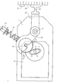
Die Zeichnung zeigt eine Montaqewand 1 eines Trockenrasierapparates, an der ein Synchronmotor 3 befestigt ist. Die Antriebswelle 5 des Synchronmotors steht senkrecht aus ihm hervor und weist nach oben aus der Zeichenebene heraus. Auf der Antriebswelle 5 ist ein Nocken 7 angeordnet, der auf seiner Übertragungsfläche 9 mit einer etwa 1 mm starken Gummischicht 11 bedeckt ist.The drawing shows a
Mit dem Nocken wirkt eine,Rolle 13 zusammen, die in einem Lagerbügel 15 gehalten ist. Der Lagerbügel 15 kann um eine Achse 17 schwenken. Im Bereich der Rollenachse 19 drückt gegen den Bügel 15 eine Feder 21, deren Vorspannung mit Hilfe einer Stellschraube 23 einstellbar ist.A,
Der Übertragungshebel 15 ist über einen Mitnehmer 27 mit einem alternierend hin und her beweglichen Untermesser 29 eines Vibrationsrasierers verbunden, das in Lagern 31 geführt ist. Ein nicht näher beschriebenes Gelenk, beispielsweise ein Filmgelenk 33, hebt die starre Verbindung zwischen dem Schneidelemnt 29 und dem Mitnehmer 27 auf.The
Auf der Oberfläche 35 der Rolle 13 kann eine Gummischicht 37 angeordnet sein, die etwa 1 mm dick ist. Diese Gummischicht 37 kann an die Stelle der Gummischicht 11 auf dem Nocken 7 treten. Es ist aber auch möglich, beide Gummischichten miteinander zusammenwirken zu lassen. Ebensogut ist es möglich, sowohl den ganzen Nocken als auch die ganze Rolle aus Gummi oder einem elastischen Material zu bilden.A
Claims (4)
Priority Applications (1)
| Application Number | Priority Date | Filing Date | Title |
|---|---|---|---|
| AT85200138T ATE43092T1 (en) | 1984-02-08 | 1985-02-07 | DRIVE DEVICE FOR A VIBRATION DRY SHAVER WITH A SHAVER FOIL AND A RECIPROCATING CUTTING ELEMENT AND DRIVEN BY A SINGLE-PHASE SYNCHRONOUS MOTOR. |
Applications Claiming Priority (2)
| Application Number | Priority Date | Filing Date | Title |
|---|---|---|---|
| DE3404296A DE3404296A1 (en) | 1984-02-08 | 1984-02-08 | DRIVING DEVICE FOR A VIBRATION DRY SHAVER WITH A SHEAR FILM AND A MOVING CUTTING ELEMENT AND DRIVE THROUGH A SINGLE-PHASE SYNCHRONOUS MOTOR |
| DE3404296 | 1984-02-08 |
Publications (3)
| Publication Number | Publication Date |
|---|---|
| EP0152143A2 true EP0152143A2 (en) | 1985-08-21 |
| EP0152143A3 EP0152143A3 (en) | 1986-05-28 |
| EP0152143B1 EP0152143B1 (en) | 1989-05-17 |
Family
ID=6227031
Family Applications (1)
| Application Number | Title | Priority Date | Filing Date |
|---|---|---|---|
| EP85200138A Expired EP0152143B1 (en) | 1984-02-08 | 1985-02-07 | Reciprocating drive assembly for shearfoil razor with singlephase synchronous motor |
Country Status (6)
| Country | Link |
|---|---|
| US (1) | US4606121A (en) |
| EP (1) | EP0152143B1 (en) |
| JP (1) | JPS60185580A (en) |
| AT (1) | ATE43092T1 (en) |
| CA (1) | CA1240137A (en) |
| DE (2) | DE3404296A1 (en) |
Cited By (1)
| Publication number | Priority date | Publication date | Assignee | Title |
|---|---|---|---|---|
| EP0322073A1 (en) * | 1987-12-23 | 1989-06-28 | Philips Patentverwaltung GmbH | Dry shaver with a knife drive transmission |
Families Citing this family (5)
| Publication number | Priority date | Publication date | Assignee | Title |
|---|---|---|---|---|
| DE3610772C1 (en) * | 1986-03-29 | 1987-06-04 | Philips Patentverwaltung | Small household appliance that is driven by a single-phase synchronous motor |
| US5007169A (en) * | 1989-12-11 | 1991-04-16 | Warner-Lambert Company | Vibrating razor |
| US20070234572A1 (en) * | 2006-04-05 | 2007-10-11 | Hannan Jeremiah M | Orbiting triple head electric shaver |
| US20160226364A1 (en) * | 2015-01-30 | 2016-08-04 | Sunbeam Products, Inc. | Electric Hair Clipper/Trimmer |
| CN106346517B (en) * | 2016-08-25 | 2018-09-25 | 上海奔腾电工有限公司 | A kind of reciprocating razor of angle driving structure |
Citations (4)
| Publication number | Priority date | Publication date | Assignee | Title |
|---|---|---|---|---|
| DE1043867B (en) * | 1956-08-31 | 1958-11-13 | Siemens Ag | Dry shaver |
| DE1268465B (en) * | 1965-02-02 | 1968-05-16 | Ibm Deutschland | Cam drive |
| US3857296A (en) * | 1971-07-23 | 1974-12-31 | Garbo P | Vibration-damped rotatable drive member |
| EP0045107A1 (en) * | 1980-07-28 | 1982-02-03 | Koninklijke Philips Electronics N.V. | Electric dry shaver |
Family Cites Families (6)
| Publication number | Priority date | Publication date | Assignee | Title |
|---|---|---|---|---|
| US2203021A (en) * | 1937-09-07 | 1940-06-04 | Ralph E Jones | Mechanical shaving or hair clipping device |
| US2287686A (en) * | 1940-01-29 | 1942-06-23 | Ralph E Jones | Shaving or hair clipping apparatus |
| NL94301C (en) * | 1956-02-29 | |||
| US3714711A (en) * | 1970-12-30 | 1973-02-06 | Sperry Rand Corp | Cutter drive member means for electric dry shaver |
| US3858314A (en) * | 1973-06-20 | 1975-01-07 | Schick Inc | Drive assembly for an electric shaver |
| JPS6041953B2 (en) * | 1979-03-16 | 1985-09-19 | 松下電工株式会社 | Electric reciprocating drive device |
-
1984
- 1984-02-08 DE DE3404296A patent/DE3404296A1/en not_active Ceased
-
1985
- 1985-02-04 US US06/698,002 patent/US4606121A/en not_active Expired - Fee Related
- 1985-02-05 JP JP60019368A patent/JPS60185580A/en active Pending
- 1985-02-07 EP EP85200138A patent/EP0152143B1/en not_active Expired
- 1985-02-07 AT AT85200138T patent/ATE43092T1/en active
- 1985-02-07 DE DE8585200138T patent/DE3570203D1/en not_active Expired
- 1985-02-07 CA CA000473773A patent/CA1240137A/en not_active Expired
Patent Citations (4)
| Publication number | Priority date | Publication date | Assignee | Title |
|---|---|---|---|---|
| DE1043867B (en) * | 1956-08-31 | 1958-11-13 | Siemens Ag | Dry shaver |
| DE1268465B (en) * | 1965-02-02 | 1968-05-16 | Ibm Deutschland | Cam drive |
| US3857296A (en) * | 1971-07-23 | 1974-12-31 | Garbo P | Vibration-damped rotatable drive member |
| EP0045107A1 (en) * | 1980-07-28 | 1982-02-03 | Koninklijke Philips Electronics N.V. | Electric dry shaver |
Cited By (1)
| Publication number | Priority date | Publication date | Assignee | Title |
|---|---|---|---|---|
| EP0322073A1 (en) * | 1987-12-23 | 1989-06-28 | Philips Patentverwaltung GmbH | Dry shaver with a knife drive transmission |
Also Published As
| Publication number | Publication date |
|---|---|
| DE3404296A1 (en) | 1985-08-14 |
| ATE43092T1 (en) | 1989-06-15 |
| EP0152143A3 (en) | 1986-05-28 |
| JPS60185580A (en) | 1985-09-21 |
| US4606121A (en) | 1986-08-19 |
| EP0152143B1 (en) | 1989-05-17 |
| DE3570203D1 (en) | 1989-06-22 |
| CA1240137A (en) | 1988-08-09 |
Similar Documents
| Publication | Publication Date | Title |
|---|---|---|
| DE4302392C2 (en) | Encapsulated double cylinder rotary piston compressor and method for its assembly | |
| EP0152143B1 (en) | Reciprocating drive assembly for shearfoil razor with singlephase synchronous motor | |
| DE2501748A1 (en) | PRESS WITH KNEE DRIVES | |
| DE8532599U1 (en) | Shredding device | |
| DE2539439A1 (en) | MOTOR VIBRATING DRIVE FOR ONE SHAFT | |
| DE2818667B2 (en) | Machine for polishing rotationally symmetrical workpieces in magnetizable grinding powder held between its poles by a magnet system | |
| DE2727888C2 (en) | Electric starter | |
| DE2532546A1 (en) | CURVE PENS WITH ROTATING BASE | |
| DE102016110651A1 (en) | Apparatus and method for trimming glass sheets | |
| DE4315432A1 (en) | Unit for delivering fuel from a fuel tank to the internal combustion engine of a motor vehicle | |
| DE8403630U1 (en) | Drive device for a vibrating dry shaver with a shaving foil and a cutting element which can be moved back and forth and is driven by a single-phase synchronous motor | |
| DE3404297A1 (en) | DEVICE FOR A VIBRATION DEVICE DRIVEN BY MEANS OF A SINGLE-PHASE SYNCHRONOUS MOTOR | |
| DE2407401A1 (en) | SURFACE GRINDING MACHINE | |
| DE3433577C2 (en) | ||
| EP0240068A2 (en) | Small household appliance driven by a one-phase synchronous motor | |
| DE10218716B4 (en) | Press with a feed device | |
| EP0098323A1 (en) | Oscillation mechanism for reciprocating machine parts, in particular for a support of print elements in a matrix line printer | |
| DE3153173C2 (en) | Pressure roller mechanism for a printing unit | |
| DE3404299C2 (en) | Drive device for a vibration device | |
| DE19646142A1 (en) | Honing machine with honing spindle for application of honing tool | |
| DE1952664A1 (en) | Drive device for a gear drive, in particular a rack and pinion drive | |
| DE19753954C2 (en) | Device for operating the saddle carriage of a brush machine | |
| DE2538689C3 (en) | Fuel feed pumps for motor vehicles | |
| DE7234901U (en) | CUTTING MECHANISM IN PARTICULAR FOR STRIP AND TAPE MATERIAL | |
| EP1109694B1 (en) | Device for electrical longitudinal adjustment of seats in a motor vehicle |
Legal Events
| Date | Code | Title | Description |
|---|---|---|---|
| PUAI | Public reference made under article 153(3) epc to a published international application that has entered the european phase |
Free format text: ORIGINAL CODE: 0009012 |
|
| AK | Designated contracting states |
Designated state(s): AT DE FR GB |
|
| PUAL | Search report despatched |
Free format text: ORIGINAL CODE: 0009013 |
|
| AK | Designated contracting states |
Kind code of ref document: A3 Designated state(s): AT DE FR GB |
|
| 17P | Request for examination filed |
Effective date: 19861016 |
|
| RAP1 | Party data changed (applicant data changed or rights of an application transferred) |
Owner name: N.V. PHILIPS' GLOEILAMPENFABRIEKEN Owner name: PHILIPS PATENTVERWALTUNG GMBH |
|
| 17Q | First examination report despatched |
Effective date: 19880325 |
|
| GRAA | (expected) grant |
Free format text: ORIGINAL CODE: 0009210 |
|
| AK | Designated contracting states |
Kind code of ref document: B1 Designated state(s): AT DE FR GB |
|
| REF | Corresponds to: |
Ref document number: 43092 Country of ref document: AT Date of ref document: 19890615 Kind code of ref document: T |
|
| REF | Corresponds to: |
Ref document number: 3570203 Country of ref document: DE Date of ref document: 19890622 |
|
| ET | Fr: translation filed | ||
| GBT | Gb: translation of ep patent filed (gb section 77(6)(a)/1977) | ||
| PLBE | No opposition filed within time limit |
Free format text: ORIGINAL CODE: 0009261 |
|
| STAA | Information on the status of an ep patent application or granted ep patent |
Free format text: STATUS: NO OPPOSITION FILED WITHIN TIME LIMIT |
|
| 26N | No opposition filed | ||
| REG | Reference to a national code |
Ref country code: FR Ref legal event code: CD |
|
| REG | Reference to a national code |
Ref country code: FR Ref legal event code: CD |
|
| PGFP | Annual fee paid to national office [announced via postgrant information from national office to epo] |
Ref country code: FR Payment date: 20010216 Year of fee payment: 17 |
|
| PGFP | Annual fee paid to national office [announced via postgrant information from national office to epo] |
Ref country code: AT Payment date: 20010222 Year of fee payment: 17 |
|
| PGFP | Annual fee paid to national office [announced via postgrant information from national office to epo] |
Ref country code: GB Payment date: 20010227 Year of fee payment: 17 |
|
| PGFP | Annual fee paid to national office [announced via postgrant information from national office to epo] |
Ref country code: DE Payment date: 20010420 Year of fee payment: 17 |
|
| REG | Reference to a national code |
Ref country code: GB Ref legal event code: IF02 |
|
| PG25 | Lapsed in a contracting state [announced via postgrant information from national office to epo] |
Ref country code: GB Free format text: LAPSE BECAUSE OF NON-PAYMENT OF DUE FEES Effective date: 20020207 Ref country code: AT Free format text: LAPSE BECAUSE OF NON-PAYMENT OF DUE FEES Effective date: 20020207 |
|
| PG25 | Lapsed in a contracting state [announced via postgrant information from national office to epo] |
Ref country code: DE Free format text: LAPSE BECAUSE OF NON-PAYMENT OF DUE FEES Effective date: 20020903 |
|
| GBPC | Gb: european patent ceased through non-payment of renewal fee |
Effective date: 20020207 |
|
| PG25 | Lapsed in a contracting state [announced via postgrant information from national office to epo] |
Ref country code: FR Free format text: LAPSE BECAUSE OF NON-PAYMENT OF DUE FEES Effective date: 20021031 |
|
| REG | Reference to a national code |
Ref country code: FR Ref legal event code: ST |