EP0152122B2 - Compact shearing machine with scrap shears - Google Patents
Compact shearing machine with scrap shears Download PDFInfo
- Publication number
- EP0152122B2 EP0152122B2 EP85200004A EP85200004A EP0152122B2 EP 0152122 B2 EP0152122 B2 EP 0152122B2 EP 85200004 A EP85200004 A EP 85200004A EP 85200004 A EP85200004 A EP 85200004A EP 0152122 B2 EP0152122 B2 EP 0152122B2
- Authority
- EP
- European Patent Office
- Prior art keywords
- shears
- scrap
- shearing
- size
- deviator
- Prior art date
- Legal status (The legal status is an assumption and is not a legal conclusion. Google has not performed a legal analysis and makes no representation as to the accuracy of the status listed.)
- Expired - Lifetime
Links
- 238000010008 shearing Methods 0.000 title claims abstract description 31
- 238000011144 upstream manufacturing Methods 0.000 claims description 10
- 238000000034 method Methods 0.000 description 5
- 230000033001 locomotion Effects 0.000 description 4
- 238000009966 trimming Methods 0.000 description 3
- 230000005540 biological transmission Effects 0.000 description 2
- 238000003754 machining Methods 0.000 description 2
- 238000012423 maintenance Methods 0.000 description 2
- 238000010276 construction Methods 0.000 description 1
- 230000007547 defect Effects 0.000 description 1
- 238000009434 installation Methods 0.000 description 1
- 238000012544 monitoring process Methods 0.000 description 1
Images


Classifications
-
- B—PERFORMING OPERATIONS; TRANSPORTING
- B23—MACHINE TOOLS; METAL-WORKING NOT OTHERWISE PROVIDED FOR
- B23D—PLANING; SLOTTING; SHEARING; BROACHING; SAWING; FILING; SCRAPING; LIKE OPERATIONS FOR WORKING METAL BY REMOVING MATERIAL, NOT OTHERWISE PROVIDED FOR
- B23D25/00—Machines or arrangements for shearing stock while the latter is travelling otherwise than in the direction of the cut
- B23D25/14—Machines or arrangements for shearing stock while the latter is travelling otherwise than in the direction of the cut without regard to the exact dimensions of the resulting material, e.g. for cutting-up scrap
-
- B—PERFORMING OPERATIONS; TRANSPORTING
- B23—MACHINE TOOLS; METAL-WORKING NOT OTHERWISE PROVIDED FOR
- B23D—PLANING; SLOTTING; SHEARING; BROACHING; SAWING; FILING; SCRAPING; LIKE OPERATIONS FOR WORKING METAL BY REMOVING MATERIAL, NOT OTHERWISE PROVIDED FOR
- B23D31/00—Shearing machines or shearing devices covered by none or more than one of the groups B23D15/00 - B23D29/00; Combinations of shearing machines
- B23D31/04—Shearing machines or shearing devices covered by none or more than one of the groups B23D15/00 - B23D29/00; Combinations of shearing machines for trimming stock combined with devices for shredding scrap
-
- Y—GENERAL TAGGING OF NEW TECHNOLOGICAL DEVELOPMENTS; GENERAL TAGGING OF CROSS-SECTIONAL TECHNOLOGIES SPANNING OVER SEVERAL SECTIONS OF THE IPC; TECHNICAL SUBJECTS COVERED BY FORMER USPC CROSS-REFERENCE ART COLLECTIONS [XRACs] AND DIGESTS
- Y10—TECHNICAL SUBJECTS COVERED BY FORMER USPC
- Y10S—TECHNICAL SUBJECTS COVERED BY FORMER USPC CROSS-REFERENCE ART COLLECTIONS [XRACs] AND DIGESTS
- Y10S83/00—Cutting
- Y10S83/923—Waste product cutting
-
- Y—GENERAL TAGGING OF NEW TECHNOLOGICAL DEVELOPMENTS; GENERAL TAGGING OF CROSS-SECTIONAL TECHNOLOGIES SPANNING OVER SEVERAL SECTIONS OF THE IPC; TECHNICAL SUBJECTS COVERED BY FORMER USPC CROSS-REFERENCE ART COLLECTIONS [XRACs] AND DIGESTS
- Y10—TECHNICAL SUBJECTS COVERED BY FORMER USPC
- Y10T—TECHNICAL SUBJECTS COVERED BY FORMER US CLASSIFICATION
- Y10T83/00—Cutting
- Y10T83/202—With product handling means
- Y10T83/2092—Means to move, guide, or permit free fall or flight of product
- Y10T83/2209—Guide
- Y10T83/2211—Abutment in path of product being moved by work feeder
-
- Y—GENERAL TAGGING OF NEW TECHNOLOGICAL DEVELOPMENTS; GENERAL TAGGING OF CROSS-SECTIONAL TECHNOLOGIES SPANNING OVER SEVERAL SECTIONS OF THE IPC; TECHNICAL SUBJECTS COVERED BY FORMER USPC CROSS-REFERENCE ART COLLECTIONS [XRACs] AND DIGESTS
- Y10—TECHNICAL SUBJECTS COVERED BY FORMER USPC
- Y10T—TECHNICAL SUBJECTS COVERED BY FORMER US CLASSIFICATION
- Y10T83/00—Cutting
- Y10T83/465—Cutting motion of tool has component in direction of moving work
- Y10T83/4653—With means to initiate intermittent tool action
- Y10T83/4656—Tool moved in response to work-sensing means
- Y10T83/4659—With means to vary "length" of product
- Y10T83/4662—To vary an end-product "length" [e.g., "crop cut"]
-
- Y—GENERAL TAGGING OF NEW TECHNOLOGICAL DEVELOPMENTS; GENERAL TAGGING OF CROSS-SECTIONAL TECHNOLOGIES SPANNING OVER SEVERAL SECTIONS OF THE IPC; TECHNICAL SUBJECTS COVERED BY FORMER USPC CROSS-REFERENCE ART COLLECTIONS [XRACs] AND DIGESTS
- Y10—TECHNICAL SUBJECTS COVERED BY FORMER USPC
- Y10T—TECHNICAL SUBJECTS COVERED BY FORMER US CLASSIFICATION
- Y10T83/00—Cutting
- Y10T83/465—Cutting motion of tool has component in direction of moving work
- Y10T83/4705—Plural separately mounted flying cutters
-
- Y—GENERAL TAGGING OF NEW TECHNOLOGICAL DEVELOPMENTS; GENERAL TAGGING OF CROSS-SECTIONAL TECHNOLOGIES SPANNING OVER SEVERAL SECTIONS OF THE IPC; TECHNICAL SUBJECTS COVERED BY FORMER USPC CROSS-REFERENCE ART COLLECTIONS [XRACs] AND DIGESTS
- Y10—TECHNICAL SUBJECTS COVERED BY FORMER USPC
- Y10T—TECHNICAL SUBJECTS COVERED BY FORMER US CLASSIFICATION
- Y10T83/00—Cutting
- Y10T83/465—Cutting motion of tool has component in direction of moving work
- Y10T83/4714—Oscillating work shifter adjacent cutter
Definitions
- Document DE-A-2.900.013 representing the nearest prior art discloses a flying shears with two plus two blades, said two pairs of blades are needed to make the material advance in one or in the other direction. This teaching necessarily requires the arrangement of the shears on the vertical plane.
- a rolled bar 33 is normally sent to a channel 29 and sheared to size by the blade 16.
Landscapes
- Engineering & Computer Science (AREA)
- Mechanical Engineering (AREA)
- Shearing Machines (AREA)
- Scissors And Nippers (AREA)
- Shovels (AREA)
- Mechanical Treatment Of Semiconductor (AREA)
Abstract
Description
- This invention concerns a compact shearing machine with scrap shears according to the pre-chacaracterising part of claim 1. To be more exact, the invention concerns a flying-type rotating shearing machine which includes a scrap shears downstream from a main shears that cuts to size, within one single framework.
- According to the invention the shears that cuts to size and the scrap shears are driven by only one motor means through a suitable transmission.
- A deviator means is also provided which can switch the segment of bar to be sheared either towards a collection channel or towards a scrap channel by which the crop ends to be scrapped are sent to a collection bin.
- Various embodiments exist in the known art which comprise a station for scrap downstream of a flying shears. Such embodiments are generally concerned with the trimming of strips and the shredding of scrap.
- For instance. document DE-C-688.185 discloses an oscillatably suspended shredder located downstream of a circular-bladed trimming shears suitable to trim strips laterally.
- Document DE-C-724.636 discloses a shears to trim strips.
- Document DE-A-2.720.136 which describes the closest prior art discloses a flying shears downstream of which is located a deviator system with movable tubes to send rolled products to a scrap shears. The assemblage is not very compact and the two shears have separate actuation systems.
- Document DE-B-1.125.259 discloses a shredder shears with a pneumatic guide for scrap material, the shears being positioned downstream of a circular-bladed shears that trims strips.
- Document FR-A-1.355.123 discloses a flying shears of which the rotors, while rotating, can be brought alongside each other for shearing. Selection of the shearing times determines the lengths sheared.
- Document FR-A-2.134.897 describes a trimming machine for strips, with a scrap shears located downstream.
- Document GB-A-472,797 discloses a like embodiment but includes a deviator for scrap and a shears having an oscillating motion.
- Document DE-A-2.900.013 representing the nearest prior art discloses a flying shears with two plus two blades, said two pairs of blades are needed to make the material advance in one or in the other direction. This teaching necessarily requires the arrangement of the shears on the vertical plane.
- Document DE-A-1.502.767 shows the use of a common motor unit for driving two different machining units; the purpose of this arrangement is to bring in synchronism the two machining units instead of bringing all together on the same frame.
- Document DE-C-839.307 discloses deviator means arranged upstream of a shearing unit and used to bring a rolled product to two different shears, whereas the deviator means according to the present invention feed the rolled product first to one and the same shearing means and afterwards to a scrap shear channel or a shearing to size channel.
- Methods of shearing rolled bars to size are known. Plants commonly employed for this purpose normally have a scrap shears positioned upstream from the shears that cuts to size.
- Switch means, which generally consist of a pivoted vane actuated hydraulically and located upstream from the scrap shears, perform deviation of the rolled product to a scrap line when such scrap shears is working.
- Instead when, for instance, the head or tail of the rolled products is not being sheared for scrap, said switch is positioned in such a way as to let the bar continue along the conveyor line to the shears which cuts to size and which then shears the various billets to the required length.
- It is known that the head and tail of the bar may have various types of defects that make such bar and tail unacceptable for the successive processes. It is therefore necessary to crop the head or tail, as required, of the rolled product arriving.
- So as to crop the head, the first segment of the bar is deviated in correspondance with the scrap shears and is cut by the latter into a series of small crop ends which are discharged.
- When the necessary length of head of the bar has been sheared, the switch is then returned to its normal position and the remainder of the bar is sent on to be cut to size.
- An analogous method is employed to shear the tail; the tail of the bar is deviated by such switch means so as to arrive below the scrap shear blades, which shear the tail and send the various crop ends thus obtained to the collection bin, whereas the remainder of the bar proceeds so as to be cut to size.
- These known embodiments provide for the use of a hydraulic switch to deviate the head or tail to be sheared for scrap.
- Since the scrap shear blades are capable of continuous rotation, it is necessary to synchronize the actuation of the switch and the rotation of such blades, the position of which has to be known moment by moment.
- Synchronization means, such as electronic means for instance, are therefore needed to synchronize the switch and the continuously rotating blades.
- Such synchronization means take into account any lag in the actuation by the hydraulic actuator that controls the movement of the switch.
- Such type of control is not only complex and expensive but also leads to problems of timing, adjustment, setting up, maintenance, etc.
- Other known embodiments have disk shears, which perform an oblique cut on the rolled bars which is not always acceptable.
- Moreover, the known plants are rather bulky since they need to accommodate separate shears for the scrap and for cutting to size besides the necessary drawing units, and such a layout entails heavy costs of installation, shielding and operation.
- It is therefore a purpose of this invention to simplify the embodiment of a shearing machine that cuts off the head and tail for scrap and cuts the bar to size, and also to reduce the overall bulk of the whole unit cutting to size and cutting for scrap considerably.
- This is achieved by a compact shearing machine having the features disclosed in claim 1.
- The bar can go in one of two directions downstream from the shears that cuts to size, depending on the inclination of a deviator channel located upstream from the same shears.
- In the first of such directions the bar is cut to size by the shears which performs such operation, and the segments thus sheared are sent on to one or more collection channels.
- In the other position of the deviator channel immediately upstream from the shears that cuts to size, the bar passes just the same between the shear blades, but its inclination is such that it is deviated against an appropriate deviation wall located immediately downstream from the shears that cuts to size.
- In this way, after having been cut to size by that shears, the bar is sent forward to the scrap shears located immediately downstream.
- The crop ends thus cut from the segment of bar sent to the scrap shears are discharged to a collection bin.
- The invention provides for the deviation of the bar to be controlled by means of a monitoring action performed upstream from the position of the tail of the bar.
- According to the invention the switch means can be operated by actuator means of a pneumatic type. In this way it is possible to obviate the employment of a hydraulic actuator unit, which is very complicated besides being costly.
- As a variant the invention envisages the use of a hydraulic actuator only where, for reasons which will be made clear later, it is desired to cut for scrap a particularly short length of the head of the bar.
- According to the invention the shearing for scrap is made independent of the deviation applied to the bar.
- An electronic synchronization control is therefore unnecessary since there is no longer any need for perfect synchronization of the deviation with the shearing of scrap.
- As we said earlier, the invention provides only one motor to drive the shears that cuts to size and the scrap shears. Moreover, the invention obtains a great compactness of the whole assemblage, which has a considerably reduced overall bulk, a low weight and a simplified construction and is therefore less expensive than the known embodiments. Furthermore, maintenance of the whole unit is simplified.
- We shall describe hereinafter, as a non-restrictive example, a preferred embodiment of the invention with the help of the attached figures, in which:
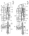
- Fig. 1 gives a partly cutaway plan view of a compact shearing machine according to the invention;
- Fig. 2 gives a side elevation of the machine of Fig. 1;
- Figs. 3 and 4 show the method of working of the shearing machine.
- In the figures a
shearing machine 10 with a scrap shears comprises, in close proximity to and upstream, adrawing unit 11 of a known type which employs rollers to draw the rolled product. - The direction of sliding of the rolled product is from left to right in the Figures.
- A
frame 14 supports the various means which constitute ashears 15 that cuts to size and ascrap shears 17. -
Such frame 14 supports also a deviator means 12 which is positioned in close proximity to and upstream from the rotor of theshears 15 that cuts to size, of which ablade 16 can be seen in Fig. 1. - Such deviator means 12 consists, in this example, of a tubular channel which can be displaced by an
actuator 13. In the Figure theactuator 13 is a pneumatic jack. - Depending on the usage conditions, the
deviator 12 sends bars into achannel 29 located in close proximity to and downstream from theblade 16 or else into achannel 30 that leads to thescrap shears 17, of which arotor 18 andblade 116 to cut for scrap can be seen. - One
single motor 19 drives both theshears shaft 31 to which is keyed apinion 20 that transmits motion to acrown wheel 22. - The
crown wheel 22 in its turn is solidly fixed to acup 124 of a brake-clutch unit 24 located in the rear part of theframe 14. - The brake-
clutch unit 24 actuates, through ashaft 32, a series of transmission pinions 23 coaxially with thecrown wheel 22. - Fig. 2 shows
trajectories 25 of theblades 16. - The motion-
input shaft 31 actuates, by means of agear wheel 120, a pair ofpinions 21, which in turn actuate therotors 18 of the scrap shears 17 to which there is fitted a variable number ofblades 116 in this example three blades perrotor 18. - In any event the number of
such blades 116 will be selected in relation to the speed of rotation pre-set for the scrap shears and also to the length of the single crop ends which it is necessary to obtain. - As can be seen from the reduction ratios applied to the train of gears shown, the speed of rotation of the
shears 15 that cuts to size is slower than that of the scrap shears 17. - This prevents any jamming of material in the gap between the two shears 15-17 since the scrap shears 17 exerts a drawing effect, which removes the crop ends from the shearing zone without any possibility of jamming.
- With particular reference to Figs. 3 and 4 the method of working is as follows.
- A rolled
bar 33 is normally sent to achannel 29 and sheared to size by theblade 16. - Whenever the tail of the
bar 33 is to be sheared, thedeviator 12 is moved to position 12B (see Fig. 4). In this way thebar 33 is deviated sideways and, when its tail is sheared by theblades 16, the front end of such tail enters thechannel 30 and thus reaches the scrap-shearing zone. - The
blades 116 of the scrap shears 17 shear such tail into a series of crop ends, which are collected in a scrap bin 26 (Fig. 1) and then discharged in a known manner. - If the head of the
bar 33 is to be sheared, thedeviator 12 is pre-set in position 12B, and in this way when the head of the rolledbar 33 arrives, it is directed at once to thechannel 30 and thus to the scrap shears 17. The crop ends are discharged into thebin 26 as detailed above. - When the head of the
bar 33 has been cropped by theblade 16 upstream from the scrap shears at 17 thedeviator 12 is brought back toposition 12A. In this way the front end of thebar 33 passes into thechannel 29 and the bar is cut to size by theshear blade 16. - In a variant where a particularly short length of cropped head is required, an
actuator 13 of a hydraulic type instead of a pneumatic type can be employed. Such hydraulic actuator serves to obtain synchronization of the sideways deviation of thebar 33 with the shearing of the head by theblades 16. - The purpose of this is to reduce the length of the portion cropped for scrap and to leave integral the greatest possible length of
bar 33, and to obtain this thebar 33 must be deviated sideways simultaneously with the shearing of the same by theshears 15. - The
deviator 27 shown downstream from the channel 29 (Figs. 1 and 2) has only the purpose of sending abar 33 sheared to size within one or the other ofcollection channels 28 shown. - It is possible to provide only one of
such collection channels 28 or more than one.
Claims (4)
- Compact shearing machine (10) for rolled bars (33), which comprises flying-type rotating shears means (15) for shearing rolled bars to size, rotating scrap shears means (17), deviator means (12) to divert the rolled bars (33) and motor means (19), whereby the scrap shears means (17) are positioned immediately downstream of the shears means (15) for shearing rolled bars to size and in the direction of sliding of the rolled bars (33), the scrap shears means (17) and shears means (15) being positioned with their axes parallel, these axes being perpendicular to the axis of the rolled bars (33), the shearing machine (10) comprising a scrap shearing channel (30) leading to the scrap shears means (17) and also a shearing to size channel (29) leading to at least one collection channel (28), the machine (10) being characterized in that the scrap shears means (17) and shears means (15) are assembled on the same frame (14) and have their respective shearing planes positioned on the same horizontal plane, and in that both the shears means (15) to shear rolled bars to size and the scrap shears means (17) are actuaded by the same motor means (19) whereby the shears means (15) are actuated by a single brake-clutch unit (24), and in that the channels (30-29) are arranged parallel and on the same horizontal plane and in that the frame (14) supports also the deviator means (12), which are arranged upstream of the shears means (15) and is movable in a horizontal plane for cooperation with the channels (30-29).
- Compact shearing machine (10) as claimed in Claim 1, in which for any position of the deviator means (12) the rolled bar (33) has a transverse position within the profile of the blades (16) that cut to size.
- Compact shearing machine (10) as claimed in Claim 1 or 2, in which the deviator means (12) is actuated pneumatically (13).
- Compact shearing machine (10) as claimed in any of Claims 1 or 2, in which the deviator means (12) is actuated hydraulically (13).
Priority Applications (1)
| Application Number | Priority Date | Filing Date | Title |
|---|---|---|---|
| AT85200004T ATE51552T1 (en) | 1984-01-27 | 1985-01-02 | COMPACT SHEARS WITH WASTE SHEARS. |
Applications Claiming Priority (2)
| Application Number | Priority Date | Filing Date | Title |
|---|---|---|---|
| IT8331184 | 1984-01-27 | ||
| IT83311/84A IT1181157B (en) | 1984-01-27 | 1984-01-27 | COMPACT SHEAR WITH SCRAPER |
Publications (4)
| Publication Number | Publication Date |
|---|---|
| EP0152122A2 EP0152122A2 (en) | 1985-08-21 |
| EP0152122A3 EP0152122A3 (en) | 1985-12-27 |
| EP0152122B1 EP0152122B1 (en) | 1990-04-04 |
| EP0152122B2 true EP0152122B2 (en) | 1994-01-12 |
Family
ID=11319927
Family Applications (1)
| Application Number | Title | Priority Date | Filing Date |
|---|---|---|---|
| EP85200004A Expired - Lifetime EP0152122B2 (en) | 1984-01-27 | 1985-01-02 | Compact shearing machine with scrap shears |
Country Status (5)
| Country | Link |
|---|---|
| US (1) | US4627320A (en) |
| EP (1) | EP0152122B2 (en) |
| AT (1) | ATE51552T1 (en) |
| DE (1) | DE3576925D1 (en) |
| IT (1) | IT1181157B (en) |
Families Citing this family (10)
| Publication number | Priority date | Publication date | Assignee | Title |
|---|---|---|---|---|
| IT1220109B (en) * | 1987-07-13 | 1990-06-06 | Danieli Off Mecc | TAIL HEAD POINTING SYSTEM WITH SAMPLING |
| IT1281448B1 (en) * | 1995-11-09 | 1998-02-18 | Danieli Off Mecc | CUTTING GROUP FOR LAMINATES |
| DE19611302A1 (en) * | 1996-03-22 | 1997-09-25 | Schloemann Siemag Ag | Method and device for separating and draining front and / or rear shoops on running rolling stock |
| DE10027470C2 (en) * | 2000-06-02 | 2002-04-11 | Bwg Bergwerk Walzwerk | Device for trimming a band, in particular a metal band, and hem strip cutting of hem strips produced in the course of the trimming |
| DE10054761A1 (en) * | 2000-11-04 | 2002-05-08 | Sms Demag Ag | Shear device for cutting metal strips or sheets, has all shears and drive rollers combined in fixed and movable basis bodies |
| US10368549B2 (en) * | 2011-01-28 | 2019-08-06 | Nissin Food Holdings Co., Ltd. | Apparatus and method for cutting noodle |
| US9278456B2 (en) | 2013-06-20 | 2016-03-08 | Siemens Industry, Inc. | High speed traversing shear |
| ES2649415T5 (en) | 2013-07-05 | 2024-09-18 | Pomini Long Rolling Mills S R L | System and method for cutting long rolled products to length from different sections of a rolling mill |
| ITMI20131670A1 (en) * | 2013-10-09 | 2015-04-10 | Danieli Off Mecc | SINGLE SHEAR FOR CUTTING AND CONVEYING MORE LAMINATES |
| CN104942355B (en) * | 2015-06-25 | 2017-06-06 | 太原科技大学 | The longitudinal bilateral cutter of heavy hydraulic hobbing type metallic plate |
Family Cites Families (13)
| Publication number | Priority date | Publication date | Assignee | Title |
|---|---|---|---|---|
| GB472797A (en) * | 1936-02-13 | 1937-09-30 | Schloemann Ag | Improvements in or relating to shears for disintegrating metal strips |
| DE688185C (en) * | 1938-08-23 | 1940-02-14 | Schloemann Akt Ges | Scrap shears for shredding seam strips |
| DE724636C (en) * | 1939-01-15 | 1942-09-01 | Demag Ag | Scissors for chopping up the seam strips or other rolled material that occur in sheet metal trimming systems |
| US2670796A (en) * | 1951-01-10 | 1954-03-02 | United States Steel Corp | Apparatus for cutting strip |
| DE1125259B (en) * | 1956-11-06 | 1962-03-08 | Otto Junker Fa | Hem guide on trimming scissors |
| US2984137A (en) * | 1959-11-13 | 1961-05-16 | Morgan Construction Co | Rotary shear blades mounted coaxially and having independent drive means |
| US3109340A (en) * | 1961-02-01 | 1963-11-05 | Morgan Construction Co | Severed product switching means |
| FR1355123A (en) * | 1963-03-28 | 1964-03-13 | Morgardshammars Mek Verkst Sa | Method and device for on-the-fly shearing |
| US3258951A (en) * | 1963-08-22 | 1966-07-05 | Morgan Construction Co | Rod switching apparatus |
| FR2134897A5 (en) * | 1971-04-23 | 1972-12-08 | Brissonneau & Lotz | |
| US3834260A (en) * | 1973-07-02 | 1974-09-10 | Morgan Construction Co | Switching mechanism for cropping and sampling front and back ends of bar product delivered from mill |
| IT1051128B (en) * | 1975-10-13 | 1981-04-21 | Simac Spa | HIGH SPEED CUTTING FLYING SHEARS WITH PARALLEL OPERATING GROUPS E.O IN COMBINED AND RALATIVE SERIES CUTTING SYSTEM |
| DE2720136A1 (en) * | 1977-05-05 | 1978-11-09 | Demag Ag | FURNISHING, DIVIDING, AND CRUSHING DEVICE OF FAST-RUNING ROLLED GOODS |
-
1984
- 1984-01-27 IT IT83311/84A patent/IT1181157B/en active
-
1985
- 1985-01-02 DE DE8585200004T patent/DE3576925D1/en not_active Expired - Fee Related
- 1985-01-02 AT AT85200004T patent/ATE51552T1/en not_active IP Right Cessation
- 1985-01-02 EP EP85200004A patent/EP0152122B2/en not_active Expired - Lifetime
- 1985-01-23 US US06/694,078 patent/US4627320A/en not_active Expired - Lifetime
Also Published As
| Publication number | Publication date |
|---|---|
| EP0152122A3 (en) | 1985-12-27 |
| IT1181157B (en) | 1987-09-23 |
| IT8483311A0 (en) | 1984-01-27 |
| EP0152122A2 (en) | 1985-08-21 |
| ATE51552T1 (en) | 1990-04-15 |
| EP0152122B1 (en) | 1990-04-04 |
| US4627320A (en) | 1986-12-09 |
| DE3576925D1 (en) | 1990-05-10 |
Similar Documents
| Publication | Publication Date | Title |
|---|---|---|
| US4176535A (en) | Apparatus for cropping, dividing and reducing rolled material at high speed | |
| US5918519A (en) | Apparatus for the manufacture of sheets of corrugated board of variable size | |
| EP0152122B1 (en) | Compact shearing machine with scrap shears | |
| EP0248354B1 (en) | Slicer | |
| CA2302724C (en) | High speed flying shear | |
| US5857370A (en) | Method of and apparatus for the trimming of leading and/or end portions of rolled products | |
| US4307594A (en) | Delivery system for hot-rolled workpieces | |
| CA2424308C (en) | Compact rotary shears | |
| GB1406200A (en) | Dividing rolled lengths of stock into merchant lengths | |
| US2815074A (en) | Sheet cutting apparatus | |
| CN1095713C (en) | High-speed shearing machine for transversely shearing off rolled band steel | |
| US3566725A (en) | Dual shearing mechanism and method | |
| EP0618033B1 (en) | High speed flying shears | |
| EP0659512A2 (en) | High speed shear for end trimming rods and the like | |
| EP1789212B1 (en) | Bar packing plant and relative process | |
| US4494427A (en) | Rotating shear for high-speed wire-rolling line | |
| US2829713A (en) | Flying shear and drive mechanism therefor | |
| US1936485A (en) | Flying shears | |
| US4204449A (en) | Flying cropping shears for hot strip | |
| EP1066129B1 (en) | Method for shearing to size rolled bars and relative shears for shearing to size | |
| US5188653A (en) | Apparatus for severing gobs from glass streams | |
| DE3841608C2 (en) | ||
| US3555952A (en) | Hammer shears for rolled stock moving at high speed | |
| US4852440A (en) | Flying shear or stamping apparatus for strip material | |
| CN220761187U (en) | High-speed flying shear chipper |
Legal Events
| Date | Code | Title | Description |
|---|---|---|---|
| PUAI | Public reference made under article 153(3) epc to a published international application that has entered the european phase |
Free format text: ORIGINAL CODE: 0009012 |
|
| AK | Designated contracting states |
Designated state(s): AT BE CH DE FR GB LI LU NL SE |
|
| PUAL | Search report despatched |
Free format text: ORIGINAL CODE: 0009013 |
|
| AK | Designated contracting states |
Designated state(s): AT BE CH DE FR GB LI LU NL SE |
|
| 17P | Request for examination filed |
Effective date: 19860310 |
|
| 17Q | First examination report despatched |
Effective date: 19871012 |
|
| GRAA | (expected) grant |
Free format text: ORIGINAL CODE: 0009210 |
|
| AK | Designated contracting states |
Kind code of ref document: B1 Designated state(s): AT BE CH DE FR GB LI LU NL SE |
|
| PG25 | Lapsed in a contracting state [announced via postgrant information from national office to epo] |
Ref country code: SE Effective date: 19900404 Ref country code: NL Effective date: 19900404 Ref country code: LI Effective date: 19900404 Ref country code: CH Effective date: 19900404 Ref country code: BE Effective date: 19900404 |
|
| REF | Corresponds to: |
Ref document number: 51552 Country of ref document: AT Date of ref document: 19900415 Kind code of ref document: T |
|
| REF | Corresponds to: |
Ref document number: 3576925 Country of ref document: DE Date of ref document: 19900510 |
|
| ET | Fr: translation filed | ||
| REG | Reference to a national code |
Ref country code: CH Ref legal event code: PL |
|
| NLV1 | Nl: lapsed or annulled due to failure to fulfill the requirements of art. 29p and 29m of the patents act | ||
| PLBI | Opposition filed |
Free format text: ORIGINAL CODE: 0009260 |
|
| PG25 | Lapsed in a contracting state [announced via postgrant information from national office to epo] |
Ref country code: LU Free format text: LAPSE BECAUSE OF NON-PAYMENT OF DUE FEES Effective date: 19910131 |
|
| 26 | Opposition filed |
Opponent name: SMS SCHLOEMANN-SIEMAG AG Effective date: 19910104 |
|
| PUAH | Patent maintained in amended form |
Free format text: ORIGINAL CODE: 0009272 |
|
| STAA | Information on the status of an ep patent application or granted ep patent |
Free format text: STATUS: PATENT MAINTAINED AS AMENDED |
|
| 27A | Patent maintained in amended form |
Effective date: 19940112 |
|
| AK | Designated contracting states |
Kind code of ref document: B2 Designated state(s): AT BE CH DE FR GB LI LU NL SE |
|
| ET3 | Fr: translation filed ** decision concerning opposition | ||
| REG | Reference to a national code |
Ref country code: GB Ref legal event code: IF02 |
|
| PGFP | Annual fee paid to national office [announced via postgrant information from national office to epo] |
Ref country code: GB Payment date: 20020102 Year of fee payment: 18 |
|
| PGFP | Annual fee paid to national office [announced via postgrant information from national office to epo] |
Ref country code: FR Payment date: 20020110 Year of fee payment: 18 |
|
| PGFP | Annual fee paid to national office [announced via postgrant information from national office to epo] |
Ref country code: AT Payment date: 20020111 Year of fee payment: 18 |
|
| PGFP | Annual fee paid to national office [announced via postgrant information from national office to epo] |
Ref country code: DE Payment date: 20020212 Year of fee payment: 18 |
|
| PG25 | Lapsed in a contracting state [announced via postgrant information from national office to epo] |
Ref country code: GB Free format text: LAPSE BECAUSE OF NON-PAYMENT OF DUE FEES Effective date: 20030102 Ref country code: AT Free format text: LAPSE BECAUSE OF NON-PAYMENT OF DUE FEES Effective date: 20030102 |
|
| PG25 | Lapsed in a contracting state [announced via postgrant information from national office to epo] |
Ref country code: DE Free format text: LAPSE BECAUSE OF NON-PAYMENT OF DUE FEES Effective date: 20030801 |
|
| GBPC | Gb: european patent ceased through non-payment of renewal fee |
Effective date: 20030102 |
|
| PG25 | Lapsed in a contracting state [announced via postgrant information from national office to epo] |
Ref country code: FR Free format text: LAPSE BECAUSE OF NON-PAYMENT OF DUE FEES Effective date: 20030930 |
|
| REG | Reference to a national code |
Ref country code: FR Ref legal event code: ST |