EP0152020A2 - Method and apparatus for cutting flat pieces, for instance metal sheets - Google Patents
Method and apparatus for cutting flat pieces, for instance metal sheets Download PDFInfo
- Publication number
- EP0152020A2 EP0152020A2 EP85101001A EP85101001A EP0152020A2 EP 0152020 A2 EP0152020 A2 EP 0152020A2 EP 85101001 A EP85101001 A EP 85101001A EP 85101001 A EP85101001 A EP 85101001A EP 0152020 A2 EP0152020 A2 EP 0152020A2
- Authority
- EP
- European Patent Office
- Prior art keywords
- workpiece
- cutting
- knife
- knives
- moved
- Prior art date
- Legal status (The legal status is an assumption and is not a legal conclusion. Google has not performed a legal analysis and makes no representation as to the accuracy of the status listed.)
- Granted
Links
- 238000005520 cutting process Methods 0.000 title claims abstract description 95
- 238000000034 method Methods 0.000 title claims abstract description 27
- 239000002184 metal Substances 0.000 title description 8
- 230000000149 penetrating effect Effects 0.000 claims abstract 2
- 230000000737 periodic effect Effects 0.000 claims description 4
- 238000007654 immersion Methods 0.000 claims description 3
- 238000010008 shearing Methods 0.000 abstract 2
- 230000004075 alteration Effects 0.000 abstract 1
- 230000000284 resting effect Effects 0.000 description 2
- 239000000725 suspension Substances 0.000 description 2
- 230000001419 dependent effect Effects 0.000 description 1
- 238000011161 development Methods 0.000 description 1
- 230000018109 developmental process Effects 0.000 description 1
- 239000013013 elastic material Substances 0.000 description 1
- 230000001404 mediated effect Effects 0.000 description 1
- 238000005096 rolling process Methods 0.000 description 1
- 230000001360 synchronised effect Effects 0.000 description 1
Images
Classifications
-
- B—PERFORMING OPERATIONS; TRANSPORTING
- B23—MACHINE TOOLS; METAL-WORKING NOT OTHERWISE PROVIDED FOR
- B23D—PLANING; SLOTTING; SHEARING; BROACHING; SAWING; FILING; SCRAPING; LIKE OPERATIONS FOR WORKING METAL BY REMOVING MATERIAL, NOT OTHERWISE PROVIDED FOR
- B23D15/00—Shearing machines or shearing devices cutting by blades which move parallel to themselves
- B23D15/06—Sheet shears
-
- B—PERFORMING OPERATIONS; TRANSPORTING
- B23—MACHINE TOOLS; METAL-WORKING NOT OTHERWISE PROVIDED FOR
- B23D—PLANING; SLOTTING; SHEARING; BROACHING; SAWING; FILING; SCRAPING; LIKE OPERATIONS FOR WORKING METAL BY REMOVING MATERIAL, NOT OTHERWISE PROVIDED FOR
- B23D15/00—Shearing machines or shearing devices cutting by blades which move parallel to themselves
- B23D15/02—Shearing machines or shearing devices cutting by blades which move parallel to themselves having both upper and lower moving blades
-
- B—PERFORMING OPERATIONS; TRANSPORTING
- B23—MACHINE TOOLS; METAL-WORKING NOT OTHERWISE PROVIDED FOR
- B23D—PLANING; SLOTTING; SHEARING; BROACHING; SAWING; FILING; SCRAPING; LIKE OPERATIONS FOR WORKING METAL BY REMOVING MATERIAL, NOT OTHERWISE PROVIDED FOR
- B23D31/00—Shearing machines or shearing devices covered by none or more than one of the groups B23D15/00 - B23D29/00; Combinations of shearing machines
Definitions
- the invention relates to a method and an apparatus for separating flat workpieces, for example sheet metal, with a pair of separating cutting knives, which are periodically moved towards and away from one another with their cutting edges interposed between the workpiece to be cut and the mutual overlap.
- the cutting direction of the two knives which are to be moved towards one another is always the longitudinal direction of their cutting edges. Since in the known methods and devices the cutting edges of the knives remain unchanged in their orientation, when cutting curves, arches or corners the workpiece must be rotated in such a way that the line of the new partial cut to be made on this workpiece extends parallel to the knife cutting edges.
- the invention is therefore based on the object in a method or a device of the type mentioned not to have to rotate the workpiece in the direction desired for the respective next partial cut in relation to the knives in order to cut a curve. to allow computer-controlled automatic feed of the workpiece through the device.
- the workpiece is moved relative to the knives substantially without changing its orientation in a coordinate system in the direction of the desired cutting line and in that the knives with their cutting edge are perpendicular to the surface of the workpiece to be cut (cutting plane)
- the axis should be rotated in the respective cutting direction required for the next separating cut, whereby the setting of the feed direction of the guide for feeding the workpiece according to the desired cutting line and the setting of the knives with their cutting edges are appropriately coupled in this cutting direction.
- the procedure is such that, by coordinate guidance of the workpiece, the front cutting edges of the knives, with which they plunge into the workpiece ahead, are in any desired cutting direction at the location of the coordinate start values for the new partial cut to be made and the cutting length is in each case continues in the direction of the next coordinate values.
- the knives are rotated in the respective new cutting direction if at least one, expediently, however, both knives are moved out of the workpiece during their periodic movement towards and away from one another or if they have emerged from their mutual overlap.
- the above-mentioned procedural measures ensure that every small part cut is made completely new and independent of the previous partial cut on the workpiece, so that any cutting line, including sharp-angled corner cuts without rounding or sharp curves with the smallest curve radius, is possible, whereby the workpiece to be cut can be pushed towards the knives without any tension.
- a free contactless feed movement of the workpiece relative to the knives is also possible. This feed movement can be controlled so that it only occurs when the knives are pulled out of the workpiece.
- the method according to the invention ensures completely waste-free separating cuts, which can be carried out at a high cutting speed that parts that fit into one another practically without play can be produced with a single cut.
- a different length of the cuts is obtained depending on the depth of overlap of the knives, so that with a correspondingly small overlap it is possible to make a faceted cut sequence only with cutting lengths of approx. 1 mm, which results in an almost homogeneous arc or circular shape of the cutting line to be produced.
- the period of time during which at least one knife is moved out of the workpiece is longer than that during which this knife overlaps with the other knife during a periodic movement towards and away from one another Workpiece is immersed.
- the depth of overlap of the knives is advantageously kept smaller the smaller the curve radius is in order to obtain curve cuts that are as continuous as possible.
- a device which, according to the invention, has a guide for the movement of the workpiece relative to the knives essentially without changing its orientation in a coordinate system, both knives with their mutually parallel cutting edges around a surface of the workpiece to be cut (cutting plane ) vertical or substantially vertical axis can be rotated, which passes through the tip or the area of the cutting edges of the knives, with which they first dip into the workpiece when they are moved towards one another.
- the two cutting knives 1, 2 are arranged vertically one above the other and provided with cutting edges 3, 4 which are oblique to one another.
- Each of these knives is stored in its own knife holder 5, 6, which are fastened at the end of each shaft 7, 8.
- the shaft 8 for the lower knife 2 is rotatable in a cylindrical bearing 9, but is non-displaceable in the axial direction
- the shaft 7 of the upper knife 1 forms a piston which can be moved up and down axially in a cylindrical bearing 10 and which the upper knife has to carry out of the cutting according to the invention required up and down movement relative to the lower knife mediated.
- the knife holder 5 for the upper knife is rotatably mounted about the axis 25.
- the tips of the the two knives have a distance from one another which corresponds approximately or at least to the thickness of the workpiece to be cut, for example a metal sheet or the like.
- an eccentric disc 11 is used, on which a crank part 13 is seated via a ball or roller bearing 12 and which is connected with its crank arm 14 via a crank pin 15 to the upper end of the shaft 7.
- the eccentric disc 11 is eccentrically seated on an eccentric shaft 16 driven by a motor (not shown).
- the eccentric shaft 16 is in turn seated via ball or roller bearings 17 in a screw eccentric 18, which can be adjusted in its rotational position via a screw shaft 19.
- the height of the eccentric shaft 16 mounted in it can be changed by rotating the screw eccentric 18, as a result of which the depth of overlap of the two knives 1, 2 and the depth of immersion of the knife 1 in the workpiece to be cut can be adjusted.
- a worm wheel 20, 21 with associated worm 22, 23 is provided on each shaft 7, 8.
- the two screws are for a synchronous drive via a gearbox, a chain or another drive element, e.g. Toothed belt or the like. Forcibly coupled together.
- the lower worm wheel 21 is fixedly connected to the rotatable shaft 8, while the upper but rotatable but rotatable shaft 7 is not fixedly connected to the upper worm wheel 20 but projects loosely through it.
- at least one driver pin 24 is seated on this knife holder and can be moved axially up and down in the worm wheel 20 via a guide bushing (not shown in the drawing) is stored. This design ensures that the knife holder rotates with the worm wheel without the upward and downward movement of the knife holder on the shaft 7 being impeded.
- the knives 1, 2 are mounted in their knife holders 5, 6 so that their axis of rotation 25 lies in the vertical front edge 26 of the knives leading to the knife tip. This ensures that the front cut edges of the better form the starting coordinates of the cutting line in each cutting direction, the direction of the next partial cut being determined by the feed direction and the dependent rotary position of the knives, which can be predetermined by coordinate control.
- a support ring 27 made of elastic material and surrounding the lower knife 2 is used to support the workpiece to be cut in the area of the cutting knives during the cutting process.
- the top of this ring is provided with a wear-resistant metal cover 28, over which the workpiece to be cut can be advanced in relation to the knives in the desired cutting direction.
- the elasticity of this support ring 27 is dimensioned such that its support surface formed by the top of the metal cover 28 is at least as high or higher than the cutting tip of the lower knife 2 or the cutting plane 29 without the workpiece being loaded, with the workpiece resting thereon and vertically downward on this workpiece, however, the cutting pressure exerted by the upper knife 1 can be pressed with its support surface so far below the cutting plane 29 that the lower knife 2 is immersed in the workpiece.
- the elastically flexible support ring can also be formed by a rubber mat or by support springs having a support surface on its upper side.
- a hold-down arm 40 is provided for holding and guiding the workpiece on its upper side, against which the upper side of the workpiece can be supported and the height of which can be adjusted relative to the workpiece.
- the two knives 1, 2 can be pivoted back and forth slightly in the direction of the workpiece feed about horizontal axes 30, 31 in the knife holders 5, 6.
- they are mounted on their front and rear edges as well as on their top edge with corresponding play in their knife holders.
- the front edges 26 of the knives are loaded via spring elements 32 mounted in the knife holders in such a way that the knives are pressed into their vertical starting pivot position shown in FIG. 1, which is fixed by abutting the rear edges of the knives against the knife holder.
- the knives can follow the workpiece with their cutting edges against the pressure of the spring elements 32 until they are moved out of the workpiece again at the end of their cutting process. whereupon they are moved back into their starting pivot position by the spring elements.
- the spring force of the spring elements 32 must be such that the possibility of the knives pivoting out about their axes 30 and 31 does not endanger the immersion of the knives with their cutting edges in the workpiece.
- the cutting knives 1, 2 are not pivoted laterally about horizontal axes, as in the embodiment shown in the drawing, but are rigidly or fixedly mounted in the knife holders 5, 6, for example by a clamping ring, a stopping of the workpiece feed is necessary during the period while the knife 1,2 immerse in the workpiece.
- the workpiece can only be fed as long as the knives with their cutting edges are outside the workpiece. This results in a jerky workpiece feed, which must be controlled in accordance with the up and down movement of the knives.
- a hydraulic drive can also be used for the up and down movement of the upper rotary shaft 7 for the upper knife 1.
- the cutting edges 3 ', 4' of the two knives 1, 2 are curved concavely with respect to the cutting plane 29.
- this results in the knives rolling down into the workpiece as it is advanced during the cutting process.
- a concavely curved, that is to say hollow-ground, cutting edge may also be expedient under certain circumstances, in particular when separating cuts are to be made with tight curves or sharp corners.
- the embodiment shown in FIG. 3 is the same as that in FIGS. 1 and 2 with the exception that the spring element for the upper knife 1 is formed by a rubber stopper 33.
- the hold-down arm 30 is omitted for reasons of clarity.
- the knife holder 6 for the lower knife 2 is rotatably mounted on the shaft 7 ', which can be moved up and down in a corresponding cylindrical bearing 10' like a piston.
- Both shafts 7, 7 ' are connected at their ends facing away from the knives 1, 2 with an eccentric disk 11, 11', on which a crank part 13, 13 'is seated via a ball or roller bearing 12, 12', which has a crank arm 14, 14 'is connected to the upper end of the shaft 7, 7' via a crank pin 15, 15 '.
- the eccentric disks 11, 12 sit eccentrically around the dimension x on an eccentric shaft 16, 16 'driven by a motor, not shown, which in turn is mounted on the machine frame via ball or roller bearings 17, 17'.
- the up and down movement of both separating knives 1, 2 is thus generated in this exemplary embodiment in the same way as in the upper separating knife 1 of the exemplary embodiment according to FIGS. 1 to 3.
- the rotary movement of the separating knives 1, 2 also takes place in this exemplary embodiment in the same way as in the upper knife of the exemplary embodiment according to FIGS. 1 and 2, that is to say via worm wheels 20, 21 driven by screws 22, 23, the rotation of which takes place via driving pins 24, 24 ' the knife holder 5,6 is transferred.
- the cutting knives are not tiltably mounted in the knife holders via tilting axes, but are replaceable in the knife holders 5,6, for example attached by clamping devices.
- the two separating knives 1, 2 protrude through openings 34, 35 in turntables 36, 37 which are rotatably supported in ball bearings 38, 39 in suspensions 41, 42, which suspensions are fastened to the machine frame.
- the turntables also rotate about the axis 25.
- the turntables serve as abutments for the sheet to be cut between them.
- pulling the separating knife 1, 2 out of the sheet metal they support the sheet metal on both sides, so that the knife cannot pull it along. This encourages the knives to slide out of the separating slot created in the sheet metal, without entanglement or tension occurring in it. This happens regardless of the rotary position of the knives, since the turntables can be rotated with the knives.
Landscapes
- Engineering & Computer Science (AREA)
- Mechanical Engineering (AREA)
- Shearing Machines (AREA)
- Perforating, Stamping-Out Or Severing By Means Other Than Cutting (AREA)
- Manufacture Of Wood Veneers (AREA)
- Control Of Cutting Processes (AREA)
- Details Of Cutting Devices (AREA)
Abstract
Description
Die Erfindung betrifft ein Verfahren und eine Vorrichtung zum Trennschneiden von flächigen Werkstücken, beispielsweise Blechen, mit einem Paar von Trennschneidmessern, welche unter Zwischenlage des zu schneidenden Werkstücks mit ihren Schneidkanten bis zur gegenseitigen Überlappung periodisch wiederkehrend aufeinanderzu- undvoneinanderwegbewegt werden.The invention relates to a method and an apparatus for separating flat workpieces, for example sheet metal, with a pair of separating cutting knives, which are periodically moved towards and away from one another with their cutting edges interposed between the workpiece to be cut and the mutual overlap.
Bei derartigen Verfahren und Vorrichtungen ist die Schnittrichtung der beiden sich aufeinander zu bewegenden Messer immer die Längsrichtung ihrer Schneidkanten. Da bei den bekannten Verfahren und Vorrichtungen die Schneidkanten der Messer in ihrer Ausrichtung unverändert bleiben, muß beim Schneiden von Kurven, Bögen oder Ecken das Werkstück jeweils so gedreht werden, daß die Linie des an diesem Werkstück vorzunehmenden neuen Teilschnittes sich parallel zu den Messerschneidkanten erstreckt.In the case of such methods and devices, the cutting direction of the two knives which are to be moved towards one another is always the longitudinal direction of their cutting edges. Since in the known methods and devices the cutting edges of the knives remain unchanged in their orientation, when cutting curves, arches or corners the workpiece must be rotated in such a way that the line of the new partial cut to be made on this workpiece extends parallel to the knife cutting edges.
Der Erfindung liegt daher die Aufgabe zugrunde, bei einem Verfahren bzw. einer Vorrichtung der eingangs genannten Gattung das Werkstück beim Schneiden von Kurven, Bögen oder Ecken nicht in die für den jeweiligen nächsten Teilschnitt gewünschte Richtung gegenüber den Messern drehen zu müssen, um einen ggfs. computergesteuerten automatischen Vorschub des Werkstücks durch die Vorrichtung hindurch ermöglichen zu können. Dies wird erfindungsgemäß dadurch erreicht, daß das Werkstück gegenüber den Messern im wesentlichen ohne Änderung seiner Ausrichtung in einem Koordinatensystem in Richtung der gewünschten Schnittlinie bewegt wird und daß dabei die Messer mit ihrer Schneidkante um eine zur Oberfläche des zu schnei- denden Werkstückes (Schneidebene) senkrechte Achse in die jeweilige, beim nächsten Trennschnitt gewünschte Schneidrichtung gedreht werden.Dabei werden zweckmäßig die Einstellung der Vorschubrichtung der Führung für den Vorschub des Werkstücks entsprechend der gewünschten Schnittlinie und die Einstellung der Messer mit ihren Schneidkanten in diese Schneidrichtung gekoppelt.The invention is therefore based on the object in a method or a device of the type mentioned not to have to rotate the workpiece in the direction desired for the respective next partial cut in relation to the knives in order to cut a curve. to allow computer-controlled automatic feed of the workpiece through the device. This is achieved according to the invention in that the workpiece is moved relative to the knives substantially without changing its orientation in a coordinate system in the direction of the desired cutting line and in that the knives with their cutting edge are perpendicular to the surface of the workpiece to be cut (cutting plane) The axis should be rotated in the respective cutting direction required for the next separating cut, whereby the setting of the feed direction of the guide for feeding the workpiece according to the desired cutting line and the setting of the knives with their cutting edges are appropriately coupled in this cutting direction.
Beim erfindungsgemäßen Verfahren wird also so vorgegangen, daß durch Koordinatenführung des Werkstücks die vorderen Schnittkanten der Messer, mit welchen diese voraus in das Werkstück eintauchen, in jeder gewünschten Schnittrichtung sich an der Stelle der Koordinatenanfangswerte für den jeweils vorzunehmenden neuen Teilschnitt befinden und die Schnittlänge sich jeweils in Richtung der nächsten Koordinatenwerte fortsetzt.In the method according to the invention, the procedure is such that, by coordinate guidance of the workpiece, the front cutting edges of the knives, with which they plunge into the workpiece ahead, are in any desired cutting direction at the location of the coordinate start values for the new partial cut to be made and the cutting length is in each case continues in the direction of the next coordinate values.
Bei einer bevorzugten Ausführungsform wird die Drehung der Messer in die jeweilige neue Schneidrichtung vorgenommen, wenn bei ihrer periodischen Aufeinanderzu- und Voneinanderwegbewegung mindestens ein, zweckmäßig jedoch beide Messer aus dem Werkstück herausbewegt sind oder wenn sie aus ihrer gegenseitigen Überlappung herausgetreten sind. Durch die vorerwähnten Verfahrensmaßnahmen wird erreicht, daß jeder noch so kleine Teilschnitt völlig neu und unabhängig vom vorangegangenen Teilschnitt am Werkstück angesetzt wird, so daß jede beliebige Schnittlinie, auch scharfwinklige Eckenschnitte ohne Verrundung oder scharfe Kurven mit kleinstem Kurvenradius möglich sind, wobei das zu schneidende Werkstück völlig spannungsfrei gegenüber den Messern vorgeschoben werden kann. Bei vollkommener Herausbewegung beider Messer aus dem Werkstück wird außerdem eine freie berührungslose Vorschubbewegung des Werkstücks gegenüber den Messern möglich. Diese Vorschubbewegung kann so gesteuert werden, daß sie nur bei aus dem Werkstück herausgezogenen Messern erfolgt. Es ist jedoch auch eine Verfahrensweise denkbar, bei der die Vorschubbewegung des Werkstücks kontinuierlich erfolgt. In diesem Falle ist es vorteilhaft, wenn die Messer während der Zeitdauer, in der sie während ihrer Bewegungsperiode in das Werkstück eingreifen, mit dem Werkstück in Schnittrichtung mitbewegt werden, bis sie nach Beendigung des Teilschnittes wieder aus dem Werkstück heraustreten, worauf sie in ihre Ausgangsstellung zurückbewegt werden.In a preferred embodiment, the knives are rotated in the respective new cutting direction if at least one, expediently, however, both knives are moved out of the workpiece during their periodic movement towards and away from one another or if they have emerged from their mutual overlap. The above-mentioned procedural measures ensure that every small part cut is made completely new and independent of the previous partial cut on the workpiece, so that any cutting line, including sharp-angled corner cuts without rounding or sharp curves with the smallest curve radius, is possible, whereby the workpiece to be cut can be pushed towards the knives without any tension. When both knives are completely moved out of the workpiece, a free contactless feed movement of the workpiece relative to the knives is also possible. This feed movement can be controlled so that it only occurs when the knives are pulled out of the workpiece. However, a procedure is also conceivable in which the feed movement of the workpiece takes place continuously. In this case, it is advantageous if the knives are moved with the workpiece in the cutting direction during the period in which they engage in the workpiece during their movement period until they come out of the workpiece again after the partial cut has been completed, whereupon they return to their starting position be moved back.
Das erfindungsgemäße Verfahren gewährleistet völlig abfallfreie Trennschnitte, die mit einer großen Schneidgeschwindigkeit durchgeführt werden können, so daß auch praktisch spielfrei ineinanderpassende Teile mit einem einzigen Schnitt hergestellt werden können. Bei Messern mit sich schräg aufeinanderzubewegenden Schneidkanten wird je nach Überlappungstiefe der Messer eine unterschiedliche Länge der Schnitte erhalten, so daß es bei entsprechend kleiner Überlappung möglich ist, nur mit Schnittlängen von ca. 1 mm eine facettenartige Schnittfolge zu legen, die eine nahezu homogene Bogen- oder Kreisform der herzustellenden Schnittlinie ergibt.The method according to the invention ensures completely waste-free separating cuts, which can be carried out at a high cutting speed that parts that fit into one another practically without play can be produced with a single cut. In the case of knives with cutting edges which can be moved obliquely towards one another, a different length of the cuts is obtained depending on the depth of overlap of the knives, so that with a correspondingly small overlap it is possible to make a faceted cut sequence only with cutting lengths of approx. 1 mm, which results in an almost homogeneous arc or circular shape of the cutting line to be produced.
Zweckmäßig wird bei dem erfindungsgemäßen Verfahren so vorgegangen, daß während einer periodischen Aufeinanderzu- und Voneinanderwegbewegung der Messer die Zeitdauer, während welcher mindestens ein Messer aus dem Werkstück herausbewegt ist, länger ist als diejenige, während der dieses Messer unter Überlappung mit dem anderen Messer in das Werkstück eingetaucht ist. Ferner wird zweckmäßig bei Kurvenschnitten die Überlappungstiefe der Messer um so geringer gehalten, je kleiner der Kurvenradius ist, um möglichst kontinuierliche Kurvenschnitte zu erhalten.Appropriately, in the method according to the invention, the period of time during which at least one knife is moved out of the workpiece is longer than that during which this knife overlaps with the other knife during a periodic movement towards and away from one another Workpiece is immersed. Furthermore, in the case of curve cuts, the depth of overlap of the knives is advantageously kept smaller the smaller the curve radius is in order to obtain curve cuts that are as continuous as possible.
Zur Durchführung des erfindungsgemäßen Verfahrens dient eine Vorrichtung, die erfindungsgemäß eine Führung für die Bewegung des Werkstücks gegenüber den Messern im wesentlichen ohne Änderung seiner Ausrichtung in einem Koordinatensystem hat, wobei beide Messer mit ihren zueinander parallelen Schneidkanten um eine zur Oberfläche des zu schneidenden Werkstückes (Schneidebene) senkrechte oder im wesentlichen senkrechte Achse drehbar sind, welche durch die Spitze bzw. den Bereich der Schneidkanten der Messer hindurchgeht, mit welchen diese bei ihrer Aufeinanderzubewegung zuerst in das Werkstück eintauchen.To implement the method according to the invention, a device is used which, according to the invention, has a guide for the movement of the workpiece relative to the knives essentially without changing its orientation in a coordinate system, both knives with their mutually parallel cutting edges around a surface of the workpiece to be cut (cutting plane ) vertical or substantially vertical axis can be rotated, which passes through the tip or the area of the cutting edges of the knives, with which they first dip into the workpiece when they are moved towards one another.
Weitere zweckmäßige bzw. vorteilhafte Weiterbildungen oder Ausführungsformen des erfindungsgemäßen Verfahrens sowie der erfindungsgemäßen Vorrichtung ergeben sich aus den Unteransprüchen.Further expedient or advantageous developments or embodiments of the method according to the invention and the device according to the invention result from the subclaims.
In der Zeichnung sind besonders vorteilhafte Ausführungsbeispiele der zur Durchführung des erfindungsgemäßen Verfahrens dienenden Vorrichtung dargestellt, die im folgenden näher beschrieben werden:
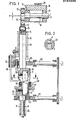
- Fig. 1 zeigt einen Vertikalschnitt durch die erfindungswesentlichen Teile des einen Ausführungsbeispiels,
- Fig. 2 ist ein Schnitt nach Linie II-II in Fig. l,
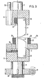
- Fig. 3 ist ein Teilquerschnitt durch die erfindungswesentlichen Teile des zweiten Ausführungsbeispiels.
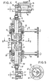
- Fig. 4 zeigt einen Vertikalschnitt durch die erfindungswesentlichen Teile eines dritten Ausführungsbeispiels.
- Fig. 5 ist ein Schnitt nach Linie V-V in Fig. 4.
- 1 shows a vertical section through the parts of the one exemplary embodiment that are essential to the invention,
- Fig. 2 is a section along line II-II in Fig. L,
- 3 is a partial cross section through the parts of the second exemplary embodiment which are essential to the invention.
- 4 shows a vertical section through the parts of a third exemplary embodiment that are essential to the invention.
- FIG. 5 is a section along line VV in FIG. 4.
Bei der in Fig. 1 und 2 dargestellten Ausführungsform sind die beiden Schneidmesser 1, 2 senkrecht übereinander angeordnet und mit zueinander schrägen Schneidkanten 3,4 versehen. Jedes dieser Messer ist in einer eigenen Messerhalterung 5,6 gelagert, die am Ende je eines Schaftes 7,8 befestigt sind. Während der Schaft 8 für das untere Messer 2 in einem zylindrischen Lager 9 drehbar, jedoch in Achsrichtung unverschiebbar gelagert ist, bildet der Schaft 7 des oberen Messers 1 einen in einem zylindrischen Lager 10 axial auf- und abbewegbaren Kolben, der dem Obermesser eine zur Durchführung des erfindungsgemäßen Trennschneidens erforderliche Auf- und Abbewegung gegenüber dem Untermesser vermittelt. An diesem auf- und abbewegbaren Schaft 7 ist die Messerhalterung 5 für das Obermesser um die Achse 25 drehbar gelagert. In der in Fig. 1 dargestellten unteren Totpunktlage ihrer Auf- und Abbewegung ist eine Überlappung der Messer 1,2 im Bereich ihrer Spitzen gegeben, während in der oberen Totpunktlage des oberen Messers 1, die in Fig. 1 gestrichelt dargestellt ist, die Spitzen der beiden Messer einen Abstand voneinander haben, der etwa oder mindestens der Dicke des zu schneidenden Werkstücks, beispielsweise einer Blechtafel oder dergl. entspricht.In the embodiment shown in FIGS. 1 and 2, the two
Zur Erzeugung der Auf- und Abbewegung des oberen Schaftes 7 dient eine Exzenterscheibe 11, auf der über ein Kugel- oder Rollenlager 12 ein Kurbelteil 13 sitzt, welches mit seinem Kurbelarm 14 über einen Kurbelzapfen 15 mit dem oberen Ende des Schaftes 7 verbunden ist. Die Exzenterscheibe 11 sitzt um das Maß x exzentrisch auf einer durch einen nicht dargestellten Motor angetriebenen Exzenterwelle 16. Bei Drehung dieser Welle 16 wird über die Exzenterscheibe 11 und das Kurbelteil 13 dem Schaft 7 eine Auf- und Abbewegung erteilt, wodurch das obere Messer 1 gegenüber dem unteren Messer 2 die eingangs erwähnte Auf- und Abbewegung durchführt, mit der das Schneiden des zu schneidenden Werkstückes vorgenommen wird.To generate the up and down movement of the
Die Exzenterwelle 16 sitzt ihrerseits über Kugel- oder Rollenlager 17 in einem Schneckenexzenter 18, der über eine Schneckenwelle 19 in seiner Drehlage einstellbar ist. Durch Drehen des Schneckenexzenters 18 kann die in ihm gelagerte Exzenterwelle 16 in ihrer Höhenlage verändert werden, wodurch die Überlappungstiefe der beiden Messer 1,2 sowie die Eintauchtiefe des Messers 1 in das zu schneidende Werkstück eingestellt werden kann.The
Um die beiden Messer 1,2 synchron mit ihren Schneidkanten 3,4 in die jeweils gewünschte Schneidrichtung drehen zu können, ist an jedem Schaft 7,8 ein Schneckenrad 20,21 mit zugehöriger Schnecke 22,23 vorgesehen. Die beiden Schnecken sind für einen Synchronantrieb über ein Getriebe, eine Kette oder ein anderes Antriebselement, z.B. Zahnriemen oder dgl., miteinander zwangsgekoppelt.In order to be able to rotate the two
Das untere Schneckenrad 21 ist mit dem drehbaren Schaft 8 fest verbunden, während der obere auf- und abbewegbare jedoch umdrehbare Schaft 7 mit dem oberen Schneckenrad 20 nicht fest verbunden sondern lose durch dieses hindurchragt. Um eine drehfeste Verbindung zwischen diesem Schneckenrad 20 und der am Schaft 7 drehbar gelagerten Messerhalterung 5 des Obermessers 1 zu erzielen, sitzt an dieser Messerhalterung mindestens ein Mitnehmerzapfen 24, der über eine in der Zeichnung nicht dargestellte Führungsbüchse in dem Schneckenrad 20 axial auf- und abbewegbar gelagert ist. Diese Ausbildung gewährleistet ein Mitdrehen der Messerhalterung mit dem Schneckenrad, ohne daß die Auf- und Abwärtsbewegung der Messerhalterung am Schaft 7 behindert wird.The lower worm wheel 21 is fixedly connected to the
Die Messer 1,2 sind in ihren Messerhalterungen 5,6 so gelagert, daß deren Drehachse 25 in der zur Messerspitze führenden senkrechten Vorderkante 26 der Messer liegt. Dadurch wird gewährleistet, daß die vorderen Schnittkanten der Besser in jeder Schnittrichtung die Anfangskoordinaten der Schnittlinie bilden, wobei durch die Vorschubrichtung und die davon abhängige Drehungstellung der Messer die Richtung des nächsten Teilschnittes bestimmt wird, die durch Koordinatensteuerung vorgegeben werden kann.The
Zur Auflagerung des zu schneidenden Werkstückes im Bereich der Schneidmesser während des Schneidvorganges dient ein das untere Messer 2 umgebender Auflagerring 27 aus elastischem Material. Die Oberseite dieses Ringes ist mit einer verschleißfesten Metallabdeckung 28 versehen, über welche hinweg das zu schneidende Werkstück gegenüber den Messern in der gewünschten Schnittrichtung vorgeschoben werden kann. Die Elastizität dieses Auflagerringes 27 ist so bemessen, daß seine von der Oberseite der Metallabdeckung 28 gebildete Auflagerfläche ohne Belastung durch das Werkstück mindestens gleich hoch oder höher als die Schneidspitze des unteren Messers 2 bzw. der Schneidebene 29 liegt, bei aufliegendem Werkstück und senkrecht nach unten auf dieses Werkstück ausgeübtem Schneiddruck des oberen Messers 1 jedoch mit ihrer Auflagerfläche so weit unter die Schneidebene 29 gedrückt werden kann, daß das untere Messer 2 in das Werkstück eintaucht. Beim Rückzug des oberen Messers 1 aus dem Werkstück heraus wird durch den federnden Auflagerring 27 das auf diesem aufliegende Werkstück so weit nach oben gedrückt, bis das untere Messer aus dem Werkstück herausgetreten ist. Der elastisch nachgiebige Auflagerring kann auch von einer Gummimatte oder von an ihrer Oberseite eine Auflagerfläche aufweisenden Abstützfedern gebildet sein.A
Zur Halterung und Führung des Werkstücks an dessen Oberseite ist ein Niederhalterarm 40 vorgesehen, gegen den sich das Werkstück mit seiner Oberseite abstützen kann und dessen Höhenlage zum Werkstück einstellbar ist.A hold-
Um ein Abstoppen des Verkstückvorschubes beim Eintauchen der Schneidmesser 1,2 in das Werkstück zu verhindern, sind die beiden Messer 1,2 um horizontale Achsen 30,31 in den Messerhalterungen 5,6 geringfügig in Richtung des Werkstückvorschubs hin- und herschwenkbar. Um diese Schwenkbarkeit dieser Messer nicht zu behindern, sind diese an ihren Vorder- und Hinterkanten sowie an ihrer Oberkante mit entsprechendem Spiel in ihren Messerhalterungen gelagert. Die Vorderkanten 26 der Messer werden über in den Messerhalterungen gelagerte Federelemente 32 so belastet, daß die Messer in ihre in Fig. 1 dargestellte senkrechte Ausgangsschwenkstellung gedrückt werden,die durch Anschlag der Hinterkanten der Messer gegen die Messerhalterung festgelegt ist. Wird nun während des Schneidvorgangs beim Eintauchen der Messer 1,2 in das Werkstück dieses weiter in Schneidrichtung vorgeschoben, können die Messer mit ihren Schneidkanten entgegen dem Druck der Federelemente 32 dem Werkstück folgen, bis sie am Ende ihres Schneidvorganges wieder aus dem Werkstück herausbewegt werden, worauf sie durch die Federelemente in ihre Ausgangsschwenkstellung zurückbewegt werden. Die Federkraft der Federelemente 32 muß dabei so bemessen sein, daß durch die Möglichkeit des Ausschwenkens der Messer um ihre Achsen 30 und 31 das Eintauchen der Messer mit ihren Schneidkanten in das Werkstück nicht gefährdet wird.In order to prevent a stopping of the crossfeed feed when the
Wenn die Schneidmesser 1,2 nicht wie bei dem in der Zeichnung dargestellten Ausführungsbeispiel seitlich um horizontale Achsen ausschwenkbar sondern starr bzw. fest in den Messerhalterungen 5,6, z.B. durch Klemmring gelagert sind, ist ein Abstoppen des Werkstückvorschubes während des Zeitraumes notwendig, während dessen die Messer 1,2 in das Werkstück eintauchen. Der Werkstückvorschub kann in diesem Falle nur erfolgen, solange die Messer mit ihren Schneidkanten sich außerhalb des Werkstücks befinden. Dies ergibt einen ruckartigen Werkstückvorschub, der entsprechend der Auf-und Abbewegung der Messer gesteuert sein muß.If the
Anstelle des Exzenterantriebs kann auch ein hydraulischer Antrieb für die Auf- und Abbewegung des oberen Drehschaftes 7 für das Obermesser 1 verwendet werden.Instead of the eccentric drive, a hydraulic drive can also be used for the up and down movement of the upper
Bei dem in Fig. 3 gezeigten Ausführungsbeispiel sind die Schneidkanten 3',4' der beiden Messer 1,2 konkav zur Schneidebene 29 gewölbt. Dies hat bei der schwenkbaren Lagerung dieser Messer um ihre horizontalen Schwenkachsen 30,31 ein abrollendes Eintauchen der Messer in das Werkstück bei dessen Vorschub während des Schneidvorganges zur Folge. Umgekehrt kann aber auch eine konkav gewölbte, also hohlgeschliffene Schneidkante unter Umständen zweckmäßig sein, insbesondere dann, wenn Trennschnitte mit engen Kurven oder scharfen Ecken ausgeführt werden sollen. Im übrigen gleicht die in Fig. 3 dargestellte Ausführungsform derjenigen in Fig. 1 und 2 mit der Ausnahme, daß das Federelement für das obere Messer 1 von einem Gummipfropfen 33 gebildet ist. In Fig. 3 ist aus Gründen der Übersichtlichkeit der Niederhaltearm 30 weggelassen.In the exemplary embodiment shown in FIG. 3, the cutting edges 3 ', 4' of the two
Bei dem in Fig. 4 und 5 dargestellten Ausführungsbeispiel ist nicht nur das Obermesser 1 sondern auch das Untermesser 2 auf- und abbewegbar. Zu diesem Zweck ist auch die Messerhalterung 6 für das Untermesser 2 drehbar am Schaft 7' gelagert, der wie ein Kolben in einem entsprechenden zylindrischen Lager 10' auf- und abbewegbar ist. Beide Schäfte 7,7' sind an ihren den Messern 1,2 abgewandten Enden jeweils mit einer Exzenterscheibe 11,11' verbunden, auf der über ein Kugel-oder Rollenlager 12,12' ein Kurbelteil 13,13' sitzt, welches mit seinem Kurbelarm 14,14' über einen Kurbelzapfen 15,15' mit dem oberen Ende des Schaftes 7,7' verbunden ist. Die Exzenterscheiben 11,12 sitzen um das Maß x exzentrisch auf einer durch einen nicht dargestellten Motor angetriebenen Exzenterwelle 16,16', die ihrerseits über Kugel- oder Rollenlager 17,17' am Maschinengestell gelagert ist. Die Auf- und Abbewegung beider Trennmesser 1,2 wird also bei diesem Ausführungsbeispiel in der gleichen Weise erzeugt wie bei dem oberen Trennmesser 1 des Ausführungsbeispiels gemäß Fig. 1 bis 3.In the embodiment shown in FIGS. 4 and 5, not only the upper knife 1 but also the
Auch die Drehbewegung der Trennmesser 1,2 erfolgt bei diesem Ausführungsbeispiel in gleicher Weise wie bei dem Obermesser des Ausführungsbeispiels gemäß Fig. 1 und 2, also über von Schnecken 22,23 angetriebene Schneckenräder 20,21, deren Drehung über Mitnehmerzapfen 24,24' auf die Messerhalterung 5,6 übertragen wird.Die Trennmesser sind hier jedoch nicht kippbar über Kippachsen in den Messerhaltern gelagert, sondern in den Messerhaltern 5,6 auswechselbar z.B. durch Klemmeinrichtungen befestigt.The rotary movement of the separating
Die beiden Trennmesser 1,2 ragen durch Durchbrüche 34,35 in Drehscheiben 36,37 hindurch, die über Kugellager 38,39 in Aufhängungen 41,42 drehbar gelagert sind, welche Aufhängungen am Maschinengestell befestigt sind. Bei Drehung der Trennmesser 1,2 um die Achse 25 drehen sich die Drehscheiben ebenfalls um die Achse 25 mit. Die Drehscheiben dienen als Widerlager für das zwischen ihnen eingelegte zu schneidende Blech. Beim Zurückziehen der Trennmesser 1,2 aus dem Blech heraus stützen sie das Blech beidseits, so daß dieses nicht von den Messern mitgezogen werden kann. Dies fördert das Herausgleiten der Messer aus dem im Blech erzeugten Trennschlitz, ohne daß in ihm Verhakungen oder Verspannungen entstehen. Dies geschieht unabhängig von der Drehstellung der Messer, da die Drehscheiben mit den Messern drehbar sind.The two separating
Claims (24)
Priority Applications (1)
| Application Number | Priority Date | Filing Date | Title |
|---|---|---|---|
| AT85101001T ATE51784T1 (en) | 1984-02-07 | 1985-01-31 | METHOD AND DEVICE FOR CUTTING FLAT WORKPIECES, FOR EXAMPLE SHEET METAL. |
Applications Claiming Priority (2)
| Application Number | Priority Date | Filing Date | Title |
|---|---|---|---|
| DE19843404234 DE3404234A1 (en) | 1984-02-07 | 1984-02-07 | METHOD AND DEVICE FOR THE CUTTING OF FLAT WORKPIECES, EXAMPLE: SHEETS |
| DE3404234 | 1984-02-07 |
Publications (3)
| Publication Number | Publication Date |
|---|---|
| EP0152020A2 true EP0152020A2 (en) | 1985-08-21 |
| EP0152020A3 EP0152020A3 (en) | 1986-10-22 |
| EP0152020B1 EP0152020B1 (en) | 1990-04-11 |
Family
ID=6226987
Family Applications (1)
| Application Number | Title | Priority Date | Filing Date |
|---|---|---|---|
| EP85101001A Expired - Lifetime EP0152020B1 (en) | 1984-02-07 | 1985-01-31 | Method and apparatus for cutting flat pieces, for instance metal sheets |
Country Status (3)
| Country | Link |
|---|---|
| EP (1) | EP0152020B1 (en) |
| AT (1) | ATE51784T1 (en) |
| DE (2) | DE3404234A1 (en) |
Cited By (3)
| Publication number | Priority date | Publication date | Assignee | Title |
|---|---|---|---|---|
| EP1074324A1 (en) * | 1999-07-27 | 2001-02-07 | Mabi Ag | Apparatus for cutting thin metal sheets |
| CN113547558A (en) * | 2021-07-13 | 2021-10-26 | 郑州中顺智能设备有限公司 | Cutting device |
| CN114833396A (en) * | 2022-03-29 | 2022-08-02 | 新疆八钢金属制品有限公司 | Steel pipe end protector ejection of compact guider |
Citations (4)
| Publication number | Priority date | Publication date | Assignee | Title |
|---|---|---|---|---|
| BE462011A (en) * | ||||
| US3830122A (en) * | 1973-03-26 | 1974-08-20 | Gerber Garment Technology Inc | Apparatus for dispensing a liquid onto a tool |
| DE2717508A1 (en) * | 1977-04-20 | 1978-10-26 | Potomac Applied Mechanics | Automatic sheet metal pattern cutter - has conveyor to support sheets during cutting by scissor shears and by computer controlled notching cutters |
| GB1535815A (en) * | 1977-06-20 | 1978-12-13 | Bowman H | Cropping machine |
-
1984
- 1984-02-07 DE DE19843404234 patent/DE3404234A1/en not_active Withdrawn
-
1985
- 1985-01-31 DE DE8585101001T patent/DE3577051D1/en not_active Expired - Lifetime
- 1985-01-31 EP EP85101001A patent/EP0152020B1/en not_active Expired - Lifetime
- 1985-01-31 AT AT85101001T patent/ATE51784T1/en active
Patent Citations (4)
| Publication number | Priority date | Publication date | Assignee | Title |
|---|---|---|---|---|
| BE462011A (en) * | ||||
| US3830122A (en) * | 1973-03-26 | 1974-08-20 | Gerber Garment Technology Inc | Apparatus for dispensing a liquid onto a tool |
| DE2717508A1 (en) * | 1977-04-20 | 1978-10-26 | Potomac Applied Mechanics | Automatic sheet metal pattern cutter - has conveyor to support sheets during cutting by scissor shears and by computer controlled notching cutters |
| GB1535815A (en) * | 1977-06-20 | 1978-12-13 | Bowman H | Cropping machine |
Cited By (3)
| Publication number | Priority date | Publication date | Assignee | Title |
|---|---|---|---|---|
| EP1074324A1 (en) * | 1999-07-27 | 2001-02-07 | Mabi Ag | Apparatus for cutting thin metal sheets |
| CN113547558A (en) * | 2021-07-13 | 2021-10-26 | 郑州中顺智能设备有限公司 | Cutting device |
| CN114833396A (en) * | 2022-03-29 | 2022-08-02 | 新疆八钢金属制品有限公司 | Steel pipe end protector ejection of compact guider |
Also Published As
| Publication number | Publication date |
|---|---|
| EP0152020B1 (en) | 1990-04-11 |
| ATE51784T1 (en) | 1990-04-15 |
| DE3577051D1 (en) | 1990-05-17 |
| DE3404234A1 (en) | 1985-08-08 |
| EP0152020A3 (en) | 1986-10-22 |
Similar Documents
| Publication | Publication Date | Title |
|---|---|---|
| EP0321590B1 (en) | Method and device for manufacturing a cutting die having a sharp cutting edge | |
| CH659203A5 (en) | CUTTING MACHINE. | |
| DE19638990A1 (en) | Cutting machine, esp. for wire slicing of blocks | |
| DE2507449A1 (en) | MACHINE SHEARS | |
| DE2826476C2 (en) | ||
| DE3321062A1 (en) | STRAIGHT WORKING SHEAR-OFF MECHANISM FOR MULTIPLE GLASS LOTS | |
| DE1511269B1 (en) | Device for radial cutting of roll-shaped bodies | |
| DE1502998A1 (en) | Scrap shredder for side trimming shears | |
| DE3415438A1 (en) | NON-IMPRESSION TUBE CUTTING DEVICE | |
| EP0152020B1 (en) | Method and apparatus for cutting flat pieces, for instance metal sheets | |
| DE3145599C2 (en) | Leather splitting machine | |
| DE2043868A1 (en) | Feed device on scissors, punching or the like | |
| DE2422815B2 (en) | Cutting device | |
| DE304676C (en) | ||
| DE3615381C2 (en) | GUIDE DEVICE FOR THE KNIFE BARS OF SHEARS FOR SHEET PROCESSING | |
| DE2341671A1 (en) | ELECTRIC EDM MACHINE | |
| DE3040447C1 (en) | Roller table for sheet metal working machines | |
| DE3022922A1 (en) | TIN SHEARS | |
| DE2700062A1 (en) | HOSE JOINTING MACHINE | |
| DE235786C (en) | ||
| DE2911576A1 (en) | FAST-RUNNING MACHINE FOR COLD FORGING SCREWS, RIVETS, ETC. HARDWARE | |
| EP0076526B1 (en) | Cutting device | |
| DE157599C (en) | ||
| DE2717508A1 (en) | Automatic sheet metal pattern cutter - has conveyor to support sheets during cutting by scissor shears and by computer controlled notching cutters | |
| DE2524773C3 (en) | Method and device for the essentially transverse cutting or perforation of a continuously running material web |
Legal Events
| Date | Code | Title | Description |
|---|---|---|---|
| PUAI | Public reference made under article 153(3) epc to a published international application that has entered the european phase |
Free format text: ORIGINAL CODE: 0009012 |
|
| AK | Designated contracting states |
Designated state(s): AT BE CH DE FR GB IT LI LU NL SE |
|
| PUAL | Search report despatched |
Free format text: ORIGINAL CODE: 0009013 |
|
| AK | Designated contracting states |
Kind code of ref document: A3 Designated state(s): AT BE CH DE FR GB IT LI LU NL SE |
|
| 17P | Request for examination filed |
Effective date: 19870304 |
|
| 17Q | First examination report despatched |
Effective date: 19881028 |
|
| GRAA | (expected) grant |
Free format text: ORIGINAL CODE: 0009210 |
|
| AK | Designated contracting states |
Kind code of ref document: B1 Designated state(s): AT BE CH DE FR GB IT LI LU NL SE |
|
| REF | Corresponds to: |
Ref document number: 51784 Country of ref document: AT Date of ref document: 19900415 Kind code of ref document: T |
|
| ITF | It: translation for a ep patent filed | ||
| GBT | Gb: translation of ep patent filed (gb section 77(6)(a)/1977) | ||
| REF | Corresponds to: |
Ref document number: 3577051 Country of ref document: DE Date of ref document: 19900517 |
|
| ET | Fr: translation filed | ||
| PG25 | Lapsed in a contracting state [announced via postgrant information from national office to epo] |
Ref country code: LU Free format text: LAPSE BECAUSE OF NON-PAYMENT OF DUE FEES Effective date: 19910131 Ref country code: GB Effective date: 19910131 Ref country code: BE Effective date: 19910131 Ref country code: AT Effective date: 19910131 |
|
| PG25 | Lapsed in a contracting state [announced via postgrant information from national office to epo] |
Ref country code: SE Effective date: 19910201 |
|
| PLBE | No opposition filed within time limit |
Free format text: ORIGINAL CODE: 0009261 |
|
| STAA | Information on the status of an ep patent application or granted ep patent |
Free format text: STATUS: NO OPPOSITION FILED WITHIN TIME LIMIT |
|
| 26N | No opposition filed | ||
| PG25 | Lapsed in a contracting state [announced via postgrant information from national office to epo] |
Ref country code: NL Effective date: 19910801 |
|
| NLV4 | Nl: lapsed or anulled due to non-payment of the annual fee | ||
| GBPC | Gb: european patent ceased through non-payment of renewal fee | ||
| PG25 | Lapsed in a contracting state [announced via postgrant information from national office to epo] |
Ref country code: FR Effective date: 19910930 |
|
| PG25 | Lapsed in a contracting state [announced via postgrant information from national office to epo] |
Ref country code: DE Effective date: 19911001 |
|
| REG | Reference to a national code |
Ref country code: FR Ref legal event code: ST |
|
| EUG | Se: european patent has lapsed |
Ref document number: 85101001.7 Effective date: 19911008 |
|
| PGFP | Annual fee paid to national office [announced via postgrant information from national office to epo] |
Ref country code: CH Payment date: 19960122 Year of fee payment: 12 |
|
| PG25 | Lapsed in a contracting state [announced via postgrant information from national office to epo] |
Ref country code: LI Effective date: 19970131 Ref country code: CH Effective date: 19970131 |
|
| REG | Reference to a national code |
Ref country code: CH Ref legal event code: PL |