EP0150975A2 - Mähmaschinen - Google Patents
Mähmaschinen Download PDFInfo
- Publication number
- EP0150975A2 EP0150975A2 EP85300421A EP85300421A EP0150975A2 EP 0150975 A2 EP0150975 A2 EP 0150975A2 EP 85300421 A EP85300421 A EP 85300421A EP 85300421 A EP85300421 A EP 85300421A EP 0150975 A2 EP0150975 A2 EP 0150975A2
- Authority
- EP
- European Patent Office
- Prior art keywords
- tractor
- mounting
- levers
- mower
- cutting head
- Prior art date
- Legal status (The legal status is an assumption and is not a legal conclusion. Google has not performed a legal analysis and makes no representation as to the accuracy of the status listed.)
- Withdrawn
Links
- 238000005520 cutting process Methods 0.000 claims abstract description 17
- 239000012530 fluid Substances 0.000 claims description 3
- 230000002441 reversible effect Effects 0.000 claims 1
- 238000010276 construction Methods 0.000 description 1
Images


Classifications
-
- A—HUMAN NECESSITIES
- A01—AGRICULTURE; FORESTRY; ANIMAL HUSBANDRY; HUNTING; TRAPPING; FISHING
- A01D—HARVESTING; MOWING
- A01D34/00—Mowers; Mowing apparatus of harvesters
- A01D34/835—Mowers; Mowing apparatus of harvesters specially adapted for particular purposes
- A01D34/86—Mowers; Mowing apparatus of harvesters specially adapted for particular purposes for use on sloping ground, e.g. on embankments or in ditches
- A01D34/866—Mounting means
Definitions
- This invention relates to mowers of the kind comprising a cutting head mounted on one end of a system of levers which is mounted at the other end on a tractor, with a series of hydraulic rams or the like for controlling the relative angles of the parts.
- the tractor may drive slowly along a road whilst the head is used to cut vegetation at the verge or trim the top or side of a hedge.
- Prior Patent GB-1 541 693 proposes a ditcher, which according to the Patent can be converted into a mower by replacing the ditching head with a cutting head, where the system of arms is mounted on a turntable which is disposed at one side of the tractor midpoint.
- the frame which supports the turntable can be arranged to be extended out from the tractor to increase the reach.
- a support leg is provided for engagement with the ground to take the cantilevered load at such an extended position.
- Prior Patent GB- 1 076 752 shows a back-hoe, that is to say a digging bucket carried at the end of a system of levers with hydraulic rams for controlling the relative angles of the parts, and which extends generally rearwardly of the tractor so as to be used for digging a ditch which extends in generally the same direction as that in which the tractor, moves although in fact the digging operation is performed whilst the tractor is stationary again using leg supports whilst the digging operation is carried out.
- This Patent describes slewing means for swinging the bucket from side-to-side including the possibility of it extending laterally of the tractor, so that the pivot about which the slewing occurs is at the same side of the tractor as that to which the system of arms extends, Figure 2 of the drawings of that prior Patent shows this.
- the actual slewing operation is carried out by engaging the bucket with the ground and then operating the slewing rams. Hence it is impossible to effect slewing whilst the vehicle is travelling, even if this were required.
- our own prior Patent GB-2 115 668 - A is concerned with mowers of the same kind as the present invention and proposes to make the mounting for the system of levers adjustable laterally of the vehicle, and in particular suggested that the mounting may comprise a beam extending laterally of the tractor, and a bracket clamped to the beam at any of a range of positions along its length, the system of levers being pivoted to the bracket.
- the beam is utilised as a hydraulic reservoir or as a power pack, or as both, and is located at the rear of the tractor. Again, in this construction also, it is necessary to stop the vehicle when any adjustment is to be effected.
- the present invention is based on the realisation that substantial advantage can be attained by making the adjustability of the mounting bracket possible whilst the tractor is actually moving.
- substantial advantage can be attained by making the adjustability of the mounting bracket possible whilst the tractor is actually moving.
- a mower comprising a cutting head pivoted to one end of a system of levers of which the other end is pivoted to a mounting on a tractor, with a series of fluid power cylinders for adjusting the angles of the parts relative to one another and hence the reach, in which the mounting is located on a beam extending laterally of the tractor, the mounting being adjustable along the length of the beam, is characterised in that power means are provided for moving the mounting along the beam whilst the tractor is in motion and without it being necessary to engage any part of the system of levers or cutting head with the ground, and the arrangement being such that the levers may extend laterally to one side of the tractor when the mounting is at the end of the beam most remote from that side of the tractor.
- the mounting may include a pivot by means of which the whole system of arms can be swung for example through 180° from one side of the tractor to the opposite side of the tractor and the beam may extend without any impediment across the tractor, and in this case the arrangement can be used for either righthand cutting or lefthand cutting whilst the tractor is travelling in one direction.
- the mounting By positioning the mounting towards the end of the beam beyond which the system of levers project, maximum reach will be afforded.
- the mounting towards the end of the beam opposite from that at which the system of levers project minimum reach will be provided most suitable for cutting very close to the tractor: especially siding a hedge in a narrow lane.
- the beam may comprise the hydraulic reservoir.
- the hydraulic reservoir may be provided at one end of the beam, and in this case the pivot between the mounting and the system of levers can be omitted so that the arrangement is effectively designed for lefthand operation, or for righthand operation (according to which side of the beam is provided with the hydraulic reservoir) but not both. It will be appreciated that when the mounting is moved along the beam towards the hydraulic reservoir, the arrangement is in the position most suitable for cutting very close to the tractor, and when the mounting is most remote from the hydraulic reservoir the maximum reach position is provided.
- the power means for moving the mounting may comprise a hydraulic motor provided on the mounting itself and arranged to drive a sprocket engaged with a chain fixed along the length of the beam.
- a hydraulic motor provided on the mounting itself and arranged to drive a sprocket engaged with a chain fixed along the length of the beam.
- This is particularly convenient since all of the other movements of the mower, that is to say the individual fluid power cylinders adjusting the angles of the levers relative to one another and also the drive for the cutting head itself may also be hydraulic all being supplied from a suitable pump driven for example from a power takeoff shaft of the tractor.
- other driving means are possible, including an electric motor especially one connected in the same way to drive a pinion along a rack.
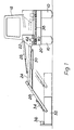
- the tractor which is somewhat diagrammaticallv illustrated comprises large rear driving wheels 10 and a cab 12, an engine compartment 14 and front wheels 16.
- a powerpack and hydraulic tank formed as a generally beam-like box 20 extending across the rear of the tractor and substantially over the length equal to the axle length of the rear wheels.
- the top of the box 20 forms a platform which supports a bracket 22 forming a mounting for a system of arms carrying the mowing head.
- First arm 24 is pivoted to the bracket and its angular position, in general meaning whether it extends horizontally from the bracket or upwardly from the bracket, is controlled by a first hydraulic ram 26.
- Second arm 28 is pivoted to the end of arm 24 and in general may extend downwardly therefrom or relatively horizontal. The angle between the two arms is controlled by second ram 30.
- the cutting head 32 may comprise a flail and mower assembly pivoted to the end of the arm 28 with the angle controlled by a ram 34.
- the mower shaft carrying the cutters is driven by hydraulic motor 36. All of the rams and the hydraulic motor are connected by appropriate flexible hoses to the powerpack and to controls operated by the driver.
- Figure 3 shows a simple sliding connection between the mounting bracket 22 and the box-beam 20, and it will be appreciated that in practice appropriate low friction devices such as roller bearings and the like may be disposed between the parts to give smooth and easy movement of the mounting bracket on the box-beam.
- a rack 38 is provided on the face of the box-beam and a pinion 40 driven by a further hydraulic motor 42 is meshed with that rack, the motor being carried on the bracket and similarly connected by hydraulic hoses to the powerpack and with a control for driver operation.
- Stops may be provided to prevent over-travel and a simple lock system such as a pin and detent to fix the mounting bracket in a predetermined position for parking.
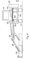
- the hydraulic powerpack and tank 50 extends at one end of a pair of parallel beams 52 54 which guide the bracket 56, and the rack is formed by a length of roller chain 58 stretched along one of the beams and fixed thereto, with a sprocket 60 driven by the motor attached to the mounting 56, to like effect.
- the mounting bracket could be positioned so that the arms project to the left or right
- Figure 2 shows the two alternatives so that in the full line position of Figure 2 the mower is arranged for cutting on the lefthand side of the tractor and in the chain-dot lines, for mowing on the righthand side of the tractor.
- the Figure 4 and 5 version is not so adapted, and in this case both sides of a road will be mown by driving the tractor first in the one direction and then in the other direction.
Landscapes
- Life Sciences & Earth Sciences (AREA)
- Environmental Sciences (AREA)
- Harvester Elements (AREA)
Applications Claiming Priority (4)
| Application Number | Priority Date | Filing Date | Title |
|---|---|---|---|
| GB848402289A GB8402289D0 (en) | 1984-01-28 | 1984-01-28 | Mowers |
| GB8402289 | 1984-01-28 | ||
| GB8410286 | 1984-04-19 | ||
| GB848410286A GB8410286D0 (en) | 1984-01-28 | 1984-04-19 | Mowers |
Publications (2)
| Publication Number | Publication Date |
|---|---|
| EP0150975A2 true EP0150975A2 (de) | 1985-08-07 |
| EP0150975A3 EP0150975A3 (de) | 1987-10-21 |
Family
ID=26287239
Family Applications (1)
| Application Number | Title | Priority Date | Filing Date |
|---|---|---|---|
| EP85300421A Withdrawn EP0150975A3 (de) | 1984-01-28 | 1985-01-23 | Mähmaschinen |
Country Status (2)
| Country | Link |
|---|---|
| US (1) | US4873818A (de) |
| EP (1) | EP0150975A3 (de) |
Cited By (5)
| Publication number | Priority date | Publication date | Assignee | Title |
|---|---|---|---|---|
| FR2638597A1 (fr) * | 1988-11-07 | 1990-05-11 | Secmair Sa | Dispositif de montage d'une tete de fauchage sur un vehicule |
| EP1097626A1 (de) * | 1999-11-04 | 2001-05-09 | Stefano Orsi | Häcksler |
| EP2949198A1 (de) * | 2014-05-26 | 2015-12-02 | Maschinenfabrik Bermatingen GmbH & Co. KG | Vorrichtung zur Bearbeitung von Bodenflächen und Halte-Vorrichtung als Bausatz für eine solche Vorrichtung |
| IT201800010084A1 (it) * | 2018-11-06 | 2020-05-06 | Orsi Group S R L | Apparecchiatura per il collegamento di una macchina agricola ad una testa di lavoro |
| IT201800010065A1 (it) * | 2018-11-06 | 2020-05-06 | Orsi Group S R L | Apparecchiatura per il collegamento di una macchina agricola ad una testa di lavoro |
Families Citing this family (24)
| Publication number | Priority date | Publication date | Assignee | Title |
|---|---|---|---|---|
| US4956965A (en) * | 1988-02-17 | 1990-09-18 | Parsons Jr Ralph L | Boom mower attachment for a tractor adjustable for cutting at either side thereof |
| US4949534A (en) * | 1989-10-17 | 1990-08-21 | Billy Evans | Swiveling lawn mower |
| US5018345A (en) * | 1990-05-29 | 1991-05-28 | Deere & Company | Crop harvester having angular draft tongue for accommodating sharp turns |
| US5210997A (en) * | 1991-05-17 | 1993-05-18 | Mountcastle Jr Deliston L | Articulated boom tractor mounted cutter assembly |
| US5813792A (en) * | 1996-11-13 | 1998-09-29 | Edwards; John W. | Coupling device |
| US5951201A (en) * | 1997-02-14 | 1999-09-14 | Jones; Mark | Striping apparatus for vehicle travel surfaces |
| US6032441A (en) | 1997-11-13 | 2000-03-07 | The Toro Company | Triplex trim mower with laterally adjustable cutting units |
| US6413012B1 (en) | 1998-02-09 | 2002-07-02 | Mark Jones | Striping apparatus for vehicle travel surfaces |
| US6684614B2 (en) | 2000-06-30 | 2004-02-03 | Owen Patrick Greenwell | Mobile power driven vegetation trimmer and line feed control |
| US6662835B1 (en) * | 2002-05-21 | 2003-12-16 | Melvin Gengler | Rotary tree cutter attachment for tractor |
| US7175380B2 (en) * | 2003-12-10 | 2007-02-13 | Alamo Group, Inc. | Slewing ring boom mower |
| US6928798B2 (en) * | 2004-01-02 | 2005-08-16 | Textron Inc. | Swing out arm for rear rotary deck |
| ATE482612T1 (de) * | 2005-04-22 | 2010-10-15 | Duecker Gerhard Gmbh & Co Kg | Mäh- und/oder schneidgerät |
| US20060288681A1 (en) * | 2005-06-10 | 2006-12-28 | Daniel Kuzub | Vertical pivoting arm apparatus for offset towing |
| US7654065B2 (en) * | 2006-09-12 | 2010-02-02 | Deere & Company | Offsetting cutting units for a grass mowing machine |
| US7437864B2 (en) * | 2007-02-16 | 2008-10-21 | Deere & Company | Shift mechanism for trim mower cutting units |
| US7475530B2 (en) | 2007-03-02 | 2009-01-13 | Textron Inc. | Articulating swing-out arm |
| US8099936B2 (en) * | 2009-01-27 | 2012-01-24 | Textron Innovations Inc. | Electrically powered flail mower |
| GB2544462A (en) * | 2015-11-04 | 2017-05-24 | Kverneland Group Kerteminde As | Carrier arm assembly |
| CN105532163B (zh) | 2016-02-04 | 2018-01-30 | 温岭正峰动力有限公司 | 一种多功能园林工具 |
| CN205357016U (zh) | 2016-02-04 | 2016-07-06 | 温岭正峰动力有限公司 | 一种多功能园林工具 |
| NL2017043B1 (en) * | 2016-06-24 | 2018-01-19 | Forage Co Bv | An agricultural machine and a method for processing crop |
| FR3054774B1 (fr) * | 2016-08-02 | 2019-05-17 | Rousseau | Dispositif de fauchage de type epareuse comportant un equipement de coupe/broyage mis en action a l'aide d'un moteur electrique |
| WO2021035088A1 (en) * | 2019-08-20 | 2021-02-25 | San Tomo, Inc. | System for hedge pruning and method for making and using the same |
Family Cites Families (13)
| Publication number | Priority date | Publication date | Assignee | Title |
|---|---|---|---|---|
| US1242505A (en) * | 1916-03-14 | 1917-10-09 | John William Wise | Hitch for tractor-impelled implements. |
| GB1076752A (en) * | 1964-05-07 | 1967-07-19 | Int Harvester Great Britain | Improvements relating to mountings for supporting implements on vehicles |
| US3241302A (en) * | 1964-11-02 | 1966-03-22 | Robert O Barry | Mowing apparatus |
| US3462925A (en) * | 1967-05-18 | 1969-08-26 | Best Equipment Co | Mowing apparatus |
| FR2087121A5 (de) * | 1970-05-05 | 1971-12-31 | Landeghem Paul Van | |
| US3949539A (en) * | 1971-12-22 | 1976-04-13 | Cartner Jack O | Hydraulic mower attachment |
| NL7513887A (nl) * | 1975-11-27 | 1977-06-01 | Continental Com & Prod | Slootreiniger. |
| DE2622770A1 (de) * | 1976-05-21 | 1977-12-08 | Hoes Maschf Klaus Gerd | Vorrichtung zum maehen und trimmen von pflanzenbewuchs an insbesondere boeschungen |
| FR2430325A1 (fr) * | 1978-07-07 | 1980-02-01 | Feyssac Guy | Dispositif d'attelage lateral pour outils agricoles ou de travaux publics |
| DE3134389A1 (de) * | 1981-08-31 | 1983-03-10 | Klöckner-Humboldt-Deutz AG Zweigniederlassung Fahr, 7702 Gottmadingen | Maehmaschine |
| GB2115668B (en) * | 1982-03-03 | 1985-10-02 | Turner Int | Mowers |
| US4426829A (en) * | 1982-07-26 | 1984-01-24 | Johnson Richard W | Grass and ditch mower |
| US4502269A (en) * | 1982-09-10 | 1985-03-05 | Cartner Jack O | Hydraulic mower head orienting apparatus for boom mowers |
-
1985
- 1985-01-23 EP EP85300421A patent/EP0150975A3/de not_active Withdrawn
-
1988
- 1988-02-25 US US07/163,195 patent/US4873818A/en not_active Expired - Fee Related
Cited By (6)
| Publication number | Priority date | Publication date | Assignee | Title |
|---|---|---|---|---|
| FR2638597A1 (fr) * | 1988-11-07 | 1990-05-11 | Secmair Sa | Dispositif de montage d'une tete de fauchage sur un vehicule |
| EP1097626A1 (de) * | 1999-11-04 | 2001-05-09 | Stefano Orsi | Häcksler |
| EP2949198A1 (de) * | 2014-05-26 | 2015-12-02 | Maschinenfabrik Bermatingen GmbH & Co. KG | Vorrichtung zur Bearbeitung von Bodenflächen und Halte-Vorrichtung als Bausatz für eine solche Vorrichtung |
| IT201800010084A1 (it) * | 2018-11-06 | 2020-05-06 | Orsi Group S R L | Apparecchiatura per il collegamento di una macchina agricola ad una testa di lavoro |
| IT201800010065A1 (it) * | 2018-11-06 | 2020-05-06 | Orsi Group S R L | Apparecchiatura per il collegamento di una macchina agricola ad una testa di lavoro |
| EP3649840A1 (de) * | 2018-11-06 | 2020-05-13 | ORSI Group S.R.L. | Vorrichtung zur stütze eines arbeitskops |
Also Published As
| Publication number | Publication date |
|---|---|
| EP0150975A3 (de) | 1987-10-21 |
| US4873818A (en) | 1989-10-17 |
Similar Documents
| Publication | Publication Date | Title |
|---|---|---|
| EP0150975A2 (de) | Mähmaschinen | |
| CA2092668C (en) | Hinged-blade roadside mower | |
| US4926621A (en) | Mowing tractor with towed mower | |
| US2743567A (en) | Multiple unit contour mower | |
| EP0262285B1 (de) | Mäher mit Pumpen in Tandemanordnung | |
| US4571147A (en) | Shovel excavator with modified upper carriage design | |
| US3103090A (en) | Specific vehicle mounting for gang mower | |
| US4340127A (en) | Tractor | |
| US4809805A (en) | Articulated vehicle | |
| US6223510B1 (en) | Mower deck with object tracing capability | |
| US3559385A (en) | Slopemower apparatus for highway and railroad rights-of-way | |
| US4185698A (en) | Adjustable auger dozer | |
| EP1364572B1 (de) | Buschmäherfahrzeug | |
| GB2081563A (en) | Grass cutting apparatus | |
| US4893456A (en) | Tractor with shiftable mowing deck | |
| US6902016B2 (en) | Pivoting panel for mechanical control disengagement | |
| US4010805A (en) | Flow through brush cutter | |
| US11007963B2 (en) | Work vehicle having ROPS | |
| US4700536A (en) | Mower with impact resistant connection | |
| US5934833A (en) | Vibratory pipe and cable laying plow | |
| US2259747A (en) | Bulldozer | |
| US5123462A (en) | Vehicle-mounted brush cutter | |
| US4501334A (en) | Wheeled excavator having a dozer blade and a boom-mounted stabilizer wheel | |
| JPH08238906A (ja) | 傾斜地走行用作業車 | |
| GB2251537A (en) | Mowers |
Legal Events
| Date | Code | Title | Description |
|---|---|---|---|
| PUAI | Public reference made under article 153(3) epc to a published international application that has entered the european phase |
Free format text: ORIGINAL CODE: 0009012 |
|
| AK | Designated contracting states |
Designated state(s): AT BE CH DE FR GB IT LI LU NL SE |
|
| PUAL | Search report despatched |
Free format text: ORIGINAL CODE: 0009013 |
|
| AK | Designated contracting states |
Kind code of ref document: A3 Designated state(s): AT BE CH DE FR GB IT LI LU NL SE |
|
| 17P | Request for examination filed |
Effective date: 19880224 |
|
| 17Q | First examination report despatched |
Effective date: 19890720 |
|
| STAA | Information on the status of an ep patent application or granted ep patent |
Free format text: STATUS: THE APPLICATION IS DEEMED TO BE WITHDRAWN |
|
| 18D | Application deemed to be withdrawn |
Effective date: 19900303 |
|
| RIN1 | Information on inventor provided before grant (corrected) |
Inventor name: TURNER, ANTHONY LEONARD |