EP0150955A2 - Assemblage de rivets à extrémité évidée - Google Patents
Assemblage de rivets à extrémité évidée Download PDFInfo
- Publication number
- EP0150955A2 EP0150955A2 EP19850300275 EP85300275A EP0150955A2 EP 0150955 A2 EP0150955 A2 EP 0150955A2 EP 19850300275 EP19850300275 EP 19850300275 EP 85300275 A EP85300275 A EP 85300275A EP 0150955 A2 EP0150955 A2 EP 0150955A2
- Authority
- EP
- European Patent Office
- Prior art keywords
- rivet
- cavity
- tool
- shank
- head
- Prior art date
- Legal status (The legal status is an assumption and is not a legal conclusion. Google has not performed a legal analysis and makes no representation as to the accuracy of the status listed.)
- Withdrawn
Links
- 238000009434 installation Methods 0.000 title claims description 24
- 239000000463 material Substances 0.000 claims abstract description 36
- 239000000758 substrate Substances 0.000 claims description 48
- 239000002131 composite material Substances 0.000 claims description 32
- 238000000034 method Methods 0.000 claims description 22
- 230000015572 biosynthetic process Effects 0.000 claims description 12
- 229910045601 alloy Inorganic materials 0.000 claims description 6
- 239000000956 alloy Substances 0.000 claims description 6
- 238000005482 strain hardening Methods 0.000 claims description 3
- 229910000556 Monel K-500 Inorganic materials 0.000 claims description 2
- 238000005452 bending Methods 0.000 claims 1
- RJSRQTFBFAJJIL-UHFFFAOYSA-N niobium titanium Chemical class [Ti].[Nb] RJSRQTFBFAJJIL-UHFFFAOYSA-N 0.000 claims 1
- 239000007787 solid Substances 0.000 description 7
- OKTJSMMVPCPJKN-UHFFFAOYSA-N Carbon Chemical compound [C] OKTJSMMVPCPJKN-UHFFFAOYSA-N 0.000 description 4
- 239000004593 Epoxy Substances 0.000 description 4
- RTAQQCXQSZGOHL-UHFFFAOYSA-N Titanium Chemical compound [Ti] RTAQQCXQSZGOHL-UHFFFAOYSA-N 0.000 description 4
- 229910002804 graphite Inorganic materials 0.000 description 4
- 239000010439 graphite Substances 0.000 description 4
- 239000010936 titanium Substances 0.000 description 4
- 229910052719 titanium Inorganic materials 0.000 description 4
- 238000003780 insertion Methods 0.000 description 3
- 230000037431 insertion Effects 0.000 description 3
- 238000004519 manufacturing process Methods 0.000 description 3
- 229910000838 Al alloy Inorganic materials 0.000 description 2
- 229910052782 aluminium Inorganic materials 0.000 description 2
- XAGFODPZIPBFFR-UHFFFAOYSA-N aluminium Chemical compound [Al] XAGFODPZIPBFFR-UHFFFAOYSA-N 0.000 description 2
- 230000006835 compression Effects 0.000 description 2
- 238000007906 compression Methods 0.000 description 2
- 238000007796 conventional method Methods 0.000 description 2
- 230000032798 delamination Effects 0.000 description 2
- 238000013461 design Methods 0.000 description 2
- 238000005516 engineering process Methods 0.000 description 2
- 229910052751 metal Inorganic materials 0.000 description 2
- 239000002184 metal Substances 0.000 description 2
- 230000036316 preload Effects 0.000 description 2
- 230000002028 premature Effects 0.000 description 2
- 229910001069 Ti alloy Inorganic materials 0.000 description 1
- 238000009825 accumulation Methods 0.000 description 1
- 230000002411 adverse Effects 0.000 description 1
- AZDRQVAHHNSJOQ-UHFFFAOYSA-N alumane Chemical group [AlH3] AZDRQVAHHNSJOQ-UHFFFAOYSA-N 0.000 description 1
- 230000000712 assembly Effects 0.000 description 1
- 238000000429 assembly Methods 0.000 description 1
- 238000005266 casting Methods 0.000 description 1
- 238000005260 corrosion Methods 0.000 description 1
- 230000007797 corrosion Effects 0.000 description 1
- 238000011161 development Methods 0.000 description 1
- 230000018109 developmental process Effects 0.000 description 1
- 238000005553 drilling Methods 0.000 description 1
- 239000000203 mixture Substances 0.000 description 1
- 239000010955 niobium Substances 0.000 description 1
- GUCVJGMIXFAOAE-UHFFFAOYSA-N niobium atom Chemical compound [Nb] GUCVJGMIXFAOAE-UHFFFAOYSA-N 0.000 description 1
- 230000009972 noncorrosive effect Effects 0.000 description 1
- 238000004513 sizing Methods 0.000 description 1
- 229910001220 stainless steel Inorganic materials 0.000 description 1
- 230000007704 transition Effects 0.000 description 1
- 230000003313 weakening effect Effects 0.000 description 1
Images

Classifications
-
- B—PERFORMING OPERATIONS; TRANSPORTING
- B21—MECHANICAL METAL-WORKING WITHOUT ESSENTIALLY REMOVING MATERIAL; PUNCHING METAL
- B21J—FORGING; HAMMERING; PRESSING METAL; RIVETING; FORGE FURNACES
- B21J15/00—Riveting
- B21J15/02—Riveting procedures
-
- B—PERFORMING OPERATIONS; TRANSPORTING
- B21—MECHANICAL METAL-WORKING WITHOUT ESSENTIALLY REMOVING MATERIAL; PUNCHING METAL
- B21J—FORGING; HAMMERING; PRESSING METAL; RIVETING; FORGE FURNACES
- B21J15/00—Riveting
- B21J15/10—Riveting machines
- B21J15/36—Rivet sets, i.e. tools for forming heads; Mandrels for expanding parts of hollow rivets
-
- F—MECHANICAL ENGINEERING; LIGHTING; HEATING; WEAPONS; BLASTING
- F16—ENGINEERING ELEMENTS AND UNITS; GENERAL MEASURES FOR PRODUCING AND MAINTAINING EFFECTIVE FUNCTIONING OF MACHINES OR INSTALLATIONS; THERMAL INSULATION IN GENERAL
- F16B—DEVICES FOR FASTENING OR SECURING CONSTRUCTIONAL ELEMENTS OR MACHINE PARTS TOGETHER, e.g. NAILS, BOLTS, CIRCLIPS, CLAMPS, CLIPS OR WEDGES; JOINTS OR JOINTING
- F16B19/00—Bolts without screw-thread; Pins, including deformable elements; Rivets
- F16B19/04—Rivets; Spigots or the like fastened by riveting
- F16B19/08—Hollow rivets; Multi-part rivets
- F16B19/10—Hollow rivets; Multi-part rivets fastened by expanding mechanically
Definitions
- This invention pertains to the art of riveting, particularly in the aircraft industry.
- the aluminum structures were fastened together by rivets composed of relatively soft aluminum alloys.
- Later developments allowed the use of harder and stronger aluminum alloys and eventually extended to include the use of even harder, non-aluminum materials such as titanium and stainless steels.
- Conventional wisdom has always sought to have an interference fit' between the rivet and the material being fastened. The interference fit was particularly felt necessary when the rivet was to be placed in shear.
- Titanium and several titanium alloys provide the least corrosive fasteners for use with many composites.
- the major problem with all of these noncorrosive materials is that they tend to be hard materials requiring a large amount of force to upset and seat the rivets. The large force in turn increases the likelihood of damaging the softer,:: substrates, especially if they are fragile composites.
- the present invention concerns an installation tool and procedure that results in the controlled deformation or upset of a cavity rivet head at a relatively low and constant force without damage to the substrate being riveted.
- the tool of this invention forms rivet heads on rivets having a head, a shank, and a cavity in one end of the rivet.
- the tool has a projecting frustrum for deforming the cavity end of the rivet.
- a projecting member slidably extends through an aperture in' the frustrum to be inserted into the cavity in the rivet when the tool is properly aligned with the rivet.
- the projecting member insures outward collapse of the cavity end of the rivet during deformation.
- a resilient member urges the projecting member through the aperture while allowing retraction of the projecting member as it is forced back through the aperture by contact with the bottom of the rivet cavity.
- the force exerted by the projecting member on the bottom of the rivet cavity cooperates with the force exerted by the tool on the cavity end of the rivet, and further cooperates with the size and location of the cavity in the rivet to insure that the deformed head begins formation at a desired location on the shank of the rivet and that the deformed:: head is properly formed.
- the diameter and depth of a cavity in the end of the rivet opposite the preformed head affect the amount of force required to upset the cavity end of the rivet and allow the use of a far lower upsetting force than required for solid rivets.
- the cavity depth also affects the formation of the upset rivet head and in particular it affects the manner in which the material adjacent the rivet hole is deformed. If properly designed and installed, the cavity end buckles out and down during upsetting, with a fairly sharp transition between the solid shank and the cavity end of the rivet, thus minimizing the deformation of the top surface of the riveted substrate.
- the cavity depth affects the amount of shank expansion as the rivet is upset.
- the cavity is too shallow, part of the shank is upset, if too deep, there is either not as sharp a demarcation between the shank and the upset head as is desirable or the external surface of the substrate adjacent the upset end is deformed.
- the rivet used in this invention controls these factors in a new and advantageous manner.
- the installation tool has an anvil pin which is inserted into the cavity of the rivet in order to insure outward collapse or buckling of the cavity end of the rivet as the rivet is upset.
- the upsetting tool also includes a truncated cone or frustum surrounding the pin.
- the anvil pin centers the tool and causes the.. annular portion of the cavity rivet to collapse outward as the frustum upsets the cavity end of the rivet.
- the frustum may be recurved upon itself to control the expansion and shape of the upset head.
- This recurved portion of the frustum can take the form of a radially expanding cone which begins at the base of the frustum and whose largest diameter is towards the end of the upsetting frustum.
- The'angle of recurvature affects not only the shape of the upset head, but also affects the amount of force required to upset the rivet.
- This upsetting tool can be used in standard rivet guns or adapted for use in squeezer assemblies. Since the cavity in the end of the rivet results in a tubular or annular column which buckles during upsetting, the upsetting force can be almost constant during upsetting. Once the upset is near completion, the force begins to increase substantially, thereby providing an easy means for determining when the upsetting process has been completed. The use of a relatively low and constant upsetting force thus minimizes the damage to the substrate' through which the rivet extends. Proper design of the upsetting tool will also insure that the upset material is always placed between the tool and the substrate and thereby minimize the chance that the tool will strike and damage the substrate.
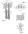
- an installation tool (18) is aligned with, but not yet upsetting a rivet (10).
- An anvil pin (20) is aligned to coincide with a cavity (16) in the end of rivet (10).
- Figure 2 shows installation tool (18) forming an upset head on rivet (10).
- Rivet (10) is shown inserted into a hole (9) through structural substrates (11) and (12).
- the rivet (10) can have any conventional preformed head (10a) and is shown with a flush-mounted, counter sunk head in Figure 1 for purposes of illustration, not limitation.
- the preformed head ' serves to define the maximum insertion position of the rivet, which in turn defines the extent to which the cavity end (14) of the rivet projects above the adjacent substrate (11).
- the rivet (10) of Figures 1 and 2 is shown in a clearance condition so that there is a space between the shank (15) and the substantially parallel, adjacent substrates (11) and (12).
- the substrates (11) and (12) are metal, such as aluminum, this clearance condition is typically undesirable and would be eliminated by either sizing the rivet (10) for a snug fit in the hole (9) through the substrates (11) and (12), or alternately, for an interference fit before insertion or after upsetting is completed.
- the substrates (11) and (12) are made of a/ composite material, such as graphite epoxy composite, it is desirable to maintain either a clearance fit as shown in Figure 1, or at most, a snug fit, even after installation is complete. An interference fit is not desirable with composites since it promotes delamination of the composite layers.
- the shape of the cavity (16) in the end of rivet (10) is typically cylindrical.
- the cavity (16) is typically concentric with the longitudinal axis of the rivet shank (15).
- the more common shape of cavity end (14) is tubular.
- the cavity (16) as shown in Figure 1 has a conical end (16a) which would result if the cavity were drilled.
- the exact shape of the bottom of the cavity' depends upon the method used to form the cavity, although a flattened bottom is preferable from a strength viewpoint.
- the cavity can be formed by any conventional method such as drilling, broaching, or integral casting.
- the exact method used to form the cavity (16) varies with the particular material used since the hardness of the material may control the most economical method of manufacture. It is desirable that the cavity (16) introduce the least practicable stress concentration into the upset rivet as such stress concentration could lead to premature failure of the riveted connection.
- the depth of the cavity (16) varies with the diameter of the rivet (10), with the material used in the rivet, and with the type of upset head which is to be formed.
- the depth of the cavity (16) can be as much as .015 inches above or below the level of the adjacent substrate (11), without significant damage to relatively fragile substrates.
- the cavity depth is measured from the end of the cylindrical side walls, not from the end of the conical bottom of the cavity.
- the cavity depth should extend not more than about .015 inches above or below the surface level of the adjacent substrate (11).
- the letters A, B, and C refer to rivet cavity end dimensions illustrated on the rivet shown in Fig. 8.
- the depth of cavity (16) should not be above the surface level of the adjacent substrate (11), nor below the depth of the counter sunk hole in the substrate (11). Too deep of a cavity weakens the rivet (10) and degrades the aerodynamic surface of the rivet head. An insufficient cavity depth upsets the rivet shank (15) and also results in an improperly formed upset head (13) which is not flush.
- the typical upset rivet head (13) formed by this invention is illustrated in Figures 2 and 3. Note that there is relatively little deformation of the substrate (11) immediately adjacent to the upset head (13) of rivet (10). The deformation to the substrate (11) is minimized because the cavity end (14) buckles outward and down onto substrate (11), while the shank (15) remains relatively constant in diameter. Thus, there is a fairly sharp demarcation between the upset head and the shank (15). The depth of cavity (16) with respect to the adjacent substrate (11) affects this sharp demarcation as previously mentioned. Also note that in the upset head condition of Figure 3, there still remains a cavity (16), but that the cavity wall now essentially comprises two parts having somewhat of a frustum conical shape and having approximately equal height F, rather than one continuous cylinder as shown in Figure 1.
- Figure 4 shows the typical condition which results' when a solid rivet is installed on a relatively soft composite substrate using conventional techniques.
- the lower edge of the upset head (40a) of rivet (40) has a more gradual radius (40a) than the rivet of Figure 3.
- the rivet shank (45) shown in Figure 4 lacks a well defined location where the upset head begins to form. Thus there is a more gradual formation of the upset head which causes at least the area (41a) of the substrate (41) immediately adjacent to the upset head (40a), to be laterally deformed. If the substrates (41) and (42) are composites, as shown in Figure 4, this lateral deformation of the head tends to delaminate the composite.
- the expansion of shank (45) using conventional riveting techniques also causes delamination of the composite layers as illustrated (41b).. and (42b).
- the rivet installation tool (18) of this invention is shown in Figu-:e 5 in greater detail.
- the tool includes an elongated tubular member (19) having an enlarged cylindrical anvil head (21).
- the outer axial end of the head (21) has a conical depression (24) having a frustum (22) projecting axially outwardly at its center.
- the smaller diameter of the frustum extends outwardly while the larger diameter or base blends or recurves into the smaller diameter portion of the depression (24), with the walls of the depression flaring radially outwardly and axially.
- the cross-section profile of the depression in the upsetting tool head (19) resembles a flattened "W” with the frustum (22) forming the middle two legs of the "W.”
- the frustum (22) has a central aperture (23) through which anvil pin (20) slideably extends.
- Spring (28) extending between a plug (30) and the pin (20) preloads anvil pin (20) into a projecting position, yet allows the pin to be forced further into the hole in the frustum (22), if a force is exerted on the pin (20) which is greater than that of the spring (28).
- An annular shoulder' (20a) on the pin engages a corresponding shoulder (19a) on the member (19) to stop or limit axial projection of the pin.
- the anvil pin (20) is sized so that it fits within the rivet cavity (16) to insure that the material in the cavity end (14) collapses or buckles outward as the cavity end (14) is deformed or upset to form the rivet head. If the anvil pin (20) is too large, the cavity end (14) will grab or bind the pin (20) during upsetting and prevent movement of pin (20) into the upsetting tool (18). If anvil pin (20) is too small, it will not adequately support the tubular walls of cavity end (14). The anvil pin (20) also helps to position the installation tool over the rivet (10). This positioning not only prevents. inadvertent damage to the substrate (11) and (12), but also assures frustum (22) is correctly aligned with the rivet (10) so that uniform column buckling of the cavity end (14) can occur.
- the frustum (22) initiates outward buckling and collapse of the cavity end (14) of the rivet (10).
- the diameter of the outer, smaller end of the frustum is about equal to the inner diameter of the rivet cavity.
- the included angle of the frustum (22) and the design of the adjacent portion (24) of the installation tool head (19) determines the size and shape of the upset rivet head.
- the included angle ⁇ of the frustum (22) is about 120°.
- the desired included angle ⁇ between the outer legs of the recurved cone section (24), varies depending upon the material of the rivet (10), upon the type of upset head to be formed, and upon the material used for the substrate (11) immediately adjacent the upset head.
- the angle ⁇ is in a range of 100° to 140°.
- the' upsetting force exerted by the installation tool (10) should be as low as possible.
- increasing the included angle between the sides of the recurved cone (24) increases the amount of force needed to upset the cavity end (14) of rivet (10).
- the included angle 9 between the sides of the recurved cone (24) also affects the size of the upset head (13) (Fig. 3) which is formed.
- a larger diameter of upset head can be achieved by using a larger included angle between the sides of the recurved cone (24).
- Generally accepted practice in aircraft manufacturing is to have the rivet diameter of the upset 1.5 times the original shank.: diameter, although an upset diameter of 1.3 times the shank diameter is acceptable. These upset sizes have been found to be sufficient to prevent pull through of the rivet under adverse loading conditions.
- the material used in rivet (10) also affects the angle between the sides of recurved cone (24).
- a larger angle between the sides of the recurved cone (24) is often used for harder rivet materials.
- An important feature of this invention is the ability to upset rivet (10) without damaging the adjacent substrate (11), and with the additional ability of controlling the expansion of shank (15).
- shank When typical rivets are upset, the entire rivet shank is placed into compression with the result that the shank permanently expands, especially near the external surface adjacent the upset heads.
- the installation tool (18) has the ability' to limit the amount of expansion of the shank (15) as well as the ability to minimize damage to the layer of substrate 11 immediately adjacent the upset head (13).
- anvil pin (20) is axially movable against the resistance of spring (28). Varying the resistance of spring (28) can control the amount of force which is introduced into the bottom (16a) of cavity (16) by contact with anvil pin (20), and thus, introduced into the shank (15). The more force exerted on shank (15), the more the shank will expand.
- spring (28) a spring or springs having different or variable spring constants
- the compression of the spring (28) can be varied by rotating the threshold retaining plug (30) to compress or release the initial spring preload.
- the amount of expansion introduced into shank (15) can thus be controlled by the amount of force exerted by anvil pin (20).
- anvil pin (20) For composite substrates (11) and (12), it is desirable to have little shank expansion unless there is a clearance fit which is to be partially or entirely eliminated by shank expansion.
- the force exerted on anvil pin (20) will be low, preferably only sufficient to insure proper positioning of anvil pin (20) in the cavity (16), and whatever additional forces are introduced by any friction or binding from the upsetting portion of cavity end (14) should those collapsing walls contact the anvil pin (20) and impede its travel into the body of upsetting tool (18).
- Eliminating the shank expansion and surface deformation adjacent the upset head (13) can eliminate the curvature or bowing inherent in riveted structures using interference fit rivets, or cavity rivets of previous inventions.
- the wall thickness of the annular portion of the' cavity end (14) is made too thin, localized buckling occurs which causes small segments of the rivet wall to deflect, with the possibility that if the deflection is inward, the anvil pin (20) may experience binding.
- the wall thickness of the cavity end (14) should be sufficiently thick to ensure uniform columnar buckling occurs.
- the cavity walls (14) must contain a sufficient volume of material to form an acceptable upset head.
- Figure 8 and Table 1 show dimensions for cavity end (14) of rivet (10) which have been found suitable in practice when made out of either TiCb alloys or K Monel, when used in a standard upset head configuration on graphite epoxy substrates.
- an included angle of 120° for frustum (22) is suitable for a standard upset head (10b) as shown in Figures 2 and 4, when used with the rivet dimensions specified in Table 1.
- the included angle between the walls of recurved cone (24) is typically 100° for materials such as TiCb and K Monel, having a sheer strength of approximately 50,000 psi.
- An angle of 140° is used for harder materials such as Beta 3 alloy. As previously indicated, 140° angle produces an upset head (10b) which is slightly larger in diameter and lower in height than does the 100° angle.
- Figure 6 shows a double flush rivet configuration which provides a relatively smooth aerodynamic surface.
- the shape of the installation tool (18) used to form this flush configuration of upset head (13) in counter-sunk' hole (49) is shown in Figure 7.
- the included angle ⁇ of the frustum (22) is increased to 140° for the flush mounted head configuration.
- the recurved cone (24) is not required, and has been eliminated.
- Table 2 shows the dimensions for rivet (10) which have been found preferable for use in the double flush mounting configuration when using K Monel as the rivet material for graphite epoxy substrates.
- FIG 8. An alternate rivet embodiment (50) is shown in Figure 8.
- This alternate embodiment has a shank (15) that is slightly reduced or undercut with respect to the cavity end (54) such that insertion of the rivet (50) through the holes (9) in the substrate ensures there will be a clearance fit between the shank (15) and the adjacent holes in the substrates being joined.
- This clearance fit is particularly desirable in composites which will tend to delaminate if there is an interference fit between the shank (45) and the adjacent substrates.
- the amount by which the shank (45) is undercut can be varied, depending upon the amount of shank expansion, if any, occurring during upsetting of the rivet head (13). The amount of undercut can also accommodate any differences in thermal expansion between the rivet (10) and the adjacent substrates.
- the shank (15) or (55) of rivets (10) and (50) is work hardened so that the shank expansion is further reduced while facilitating the upsetting of the more maleable cavity ends (14) and' (54).
- Work hardening the undercut shank (55) as shown in Figure 8 further insures a controlled expansion of shank (55) and provides a sharper demarcation between the shank and the formation of the upset rivet head (13).
Landscapes
- Engineering & Computer Science (AREA)
- Mechanical Engineering (AREA)
- General Engineering & Computer Science (AREA)
- Insertion Pins And Rivets (AREA)
Applications Claiming Priority (2)
| Application Number | Priority Date | Filing Date | Title |
|---|---|---|---|
| US57256684A | 1984-01-19 | 1984-01-19 | |
| US572566 | 1984-01-19 |
Publications (1)
| Publication Number | Publication Date |
|---|---|
| EP0150955A2 true EP0150955A2 (fr) | 1985-08-07 |
Family
ID=24288413
Family Applications (1)
| Application Number | Title | Priority Date | Filing Date |
|---|---|---|---|
| EP19850300275 Withdrawn EP0150955A2 (fr) | 1984-01-19 | 1985-01-16 | Assemblage de rivets à extrémité évidée |
Country Status (1)
| Country | Link |
|---|---|
| EP (1) | EP0150955A2 (fr) |
Cited By (5)
| Publication number | Priority date | Publication date | Assignee | Title |
|---|---|---|---|---|
| EP1094229A2 (fr) * | 1999-10-18 | 2001-04-25 | Kabushiki Kaisha Yutaka Giken | Assemblage rivé et procédé d'assemblage de deux pièces par rivets |
| DE10314544A1 (de) * | 2003-03-31 | 2004-10-14 | BSH Bosch und Siemens Hausgeräte GmbH | Formschüssige Fügeverbindung |
| EP1398440A3 (fr) * | 2002-09-16 | 2006-04-19 | ISE Innomotive Systems Europe GmbH | Charnière de porte pour véhicules avec un arrêt de porte |
| EP1712793A1 (fr) * | 2004-02-06 | 2006-10-18 | Daikin Industries, Ltd. | Compresseur et procede d installation de plaque |
| US20170073983A1 (en) * | 2014-03-06 | 2017-03-16 | Nela Gmbh | Device for smoothing |
-
1985
- 1985-01-16 EP EP19850300275 patent/EP0150955A2/fr not_active Withdrawn
Cited By (7)
| Publication number | Priority date | Publication date | Assignee | Title |
|---|---|---|---|---|
| EP1094229A2 (fr) * | 1999-10-18 | 2001-04-25 | Kabushiki Kaisha Yutaka Giken | Assemblage rivé et procédé d'assemblage de deux pièces par rivets |
| EP1094229A3 (fr) * | 1999-10-18 | 2003-05-28 | Kabushiki Kaisha Yutaka Giken | Assemblage rivé et procédé d'assemblage de deux pièces par rivets |
| EP1398440A3 (fr) * | 2002-09-16 | 2006-04-19 | ISE Innomotive Systems Europe GmbH | Charnière de porte pour véhicules avec un arrêt de porte |
| DE10314544A1 (de) * | 2003-03-31 | 2004-10-14 | BSH Bosch und Siemens Hausgeräte GmbH | Formschüssige Fügeverbindung |
| EP1712793A1 (fr) * | 2004-02-06 | 2006-10-18 | Daikin Industries, Ltd. | Compresseur et procede d installation de plaque |
| EP1712793A4 (fr) * | 2004-02-06 | 2007-10-10 | Daikin Ind Ltd | Compresseur et procede d installation de plaque |
| US20170073983A1 (en) * | 2014-03-06 | 2017-03-16 | Nela Gmbh | Device for smoothing |
Similar Documents
| Publication | Publication Date | Title |
|---|---|---|
| US4451189A (en) | Bulb rivet | |
| US7802952B2 (en) | Nut plate fastener assembly for hard metal materials | |
| US7516534B2 (en) | Method for attaching a nut element to a metal structure | |
| CA1323514C (fr) | Rivet borgne | |
| US3779127A (en) | Stress coining bolt | |
| EP1614486B1 (fr) | Dispositif de pose de rivets autoperforants avec matrice améliorée | |
| EP0398512A2 (fr) | Rivet aveugle | |
| WO2011049643A1 (fr) | Elément de fixation du type cheville-rivet | |
| US3747467A (en) | Rivet fastener system and method | |
| JP2005515072A (ja) | セルフピアシング部品、取付方法及びダイ部材 | |
| US20120324978A1 (en) | Clinch Pin Fastener | |
| US3391449A (en) | Method of making a prestressed riveted connection | |
| US3953906A (en) | Fastener assembly | |
| AU685910B2 (en) | Blind rivet | |
| US4767248A (en) | Fastener for securing panels of composite materials | |
| EP0328314B1 (fr) | Rivet aveugle | |
| EP0497455A1 (fr) | Rivet aveugle auto-bouchant | |
| US4177545A (en) | Fastening method and product | |
| US4088053A (en) | Cavity rivet assembly | |
| US4007540A (en) | Method for fabricating a cavity rivet assembly | |
| US11833576B2 (en) | Riveting method | |
| EP0150955A2 (fr) | Assemblage de rivets à extrémité évidée | |
| US5035041A (en) | Method to obtain preload in solid one-piece ductile rivet installation | |
| EP0728950A1 (fr) | Procédé pour la fixation de deux éléments et dispositif de fixation associé | |
| CN114251339A (zh) | 带槽自冲铆钉 |
Legal Events
| Date | Code | Title | Description |
|---|---|---|---|
| PUAI | Public reference made under article 153(3) epc to a published international application that has entered the european phase |
Free format text: ORIGINAL CODE: 0009012 |
|
| AK | Designated contracting states |
Designated state(s): AT BE CH DE FR GB IT LI LU NL SE |
|
| STAA | Information on the status of an ep patent application or granted ep patent |
Free format text: STATUS: THE APPLICATION IS DEEMED TO BE WITHDRAWN |
|
| 18D | Application deemed to be withdrawn |
Effective date: 19870804 |
|
| RIN1 | Information on inventor provided before grant (corrected) |
Inventor name: MOSDALE, BRIAN ERIC |