EP0150887B1 - Remote controlled agricultural machine - Google Patents
Remote controlled agricultural machine Download PDFInfo
- Publication number
- EP0150887B1 EP0150887B1 EP19850200086 EP85200086A EP0150887B1 EP 0150887 B1 EP0150887 B1 EP 0150887B1 EP 19850200086 EP19850200086 EP 19850200086 EP 85200086 A EP85200086 A EP 85200086A EP 0150887 B1 EP0150887 B1 EP 0150887B1
- Authority
- EP
- European Patent Office
- Prior art keywords
- control unit
- signals
- machine
- agricultural machine
- control
- Prior art date
- Legal status (The legal status is an assumption and is not a legal conclusion. Google has not performed a legal analysis and makes no representation as to the accuracy of the status listed.)
- Expired
Links
- 230000005540 biological transmission Effects 0.000 claims description 3
- 239000004459 forage Substances 0.000 description 7
- 238000012544 monitoring process Methods 0.000 description 5
- 230000000994 depressogenic effect Effects 0.000 description 3
- 230000002441 reversible effect Effects 0.000 description 3
- 230000001627 detrimental effect Effects 0.000 description 2
- 238000010586 diagram Methods 0.000 description 2
- 238000003306 harvesting Methods 0.000 description 2
- 230000002411 adverse Effects 0.000 description 1
- 238000004378 air conditioning Methods 0.000 description 1
- 230000000295 complement effect Effects 0.000 description 1
- 230000000881 depressing effect Effects 0.000 description 1
- 230000000694 effects Effects 0.000 description 1
- 230000007613 environmental effect Effects 0.000 description 1
- 238000009434 installation Methods 0.000 description 1
- 238000000034 method Methods 0.000 description 1
- 230000004048 modification Effects 0.000 description 1
- 238000012986 modification Methods 0.000 description 1
Images

Classifications
-
- A—HUMAN NECESSITIES
- A01—AGRICULTURE; FORESTRY; ANIMAL HUSBANDRY; HUNTING; TRAPPING; FISHING
- A01D—HARVESTING; MOWING
- A01D41/00—Combines, i.e. harvesters or mowers combined with threshing devices
- A01D41/04—Tractor-driven combines
-
- A—HUMAN NECESSITIES
- A01—AGRICULTURE; FORESTRY; ANIMAL HUSBANDRY; HUNTING; TRAPPING; FISHING
- A01D—HARVESTING; MOWING
- A01D43/00—Mowers combined with apparatus performing additional operations while mowing
- A01D43/06—Mowers combined with apparatus performing additional operations while mowing with means for collecting, gathering or loading mown material
Definitions
- This invention relates to pull-type or towable agricultural machines of the type as specified in the preamble of claim 1 and which thus, in use, are hitched to a towing vehicle such as a tractor and which are equiped for wireless remote control from said tractor.
- control box of a given pull-type machine may be coupled without the use of any connectors via a flexible cable string to the machine components to be controlled.
- a control box is suited to be attached to a support within the tractor cab with the cable string passing through e.g. a cab window which therefore has to be opened and left open during the operation of the machine. Obviously, this is even more detrimental to the sound proofing of the cab and further adversely affects the air conditioning within the cab and permits the ingress of dirt.
- Remote control means of the type as considered herebefore and for use in conjunction with pull-type agricultural machines have been described in DE-A-1.632.824.
- This document further also describes, in general terms, wireless remote controls for controlling a plurality of functions of a pull-type agricultural machine.
- a transmitter capable of transmitting electro-magnetic signals
- a receiver capable of receiving said electromagnetic signals is mounted on the agricultural machine. Different frequencies are used for distinguishing between the various command signals.
- the receiving means are operable, in response to the command signals received from the transmitter means, to actuate the appropriate actuator means associated with the machine components to be controlled.
- the wireless remote control means as disclosed in DE-A-1.632.824 are plagued with a plurality of shortcomings and drawbacks, especially when used on pull-type agricultural machines operated in combination with modern towing tractor means equiped with cabs enclosing the operator station ' thereof.
- the remote control and/or monitoring of pull-type agricultural machinery which, in accordance with the present invention uses transmitter and receiver means capable of transmitting and receiving encoded signals, is advantageous in many respects. Indeed, it not only enables wireless remote control and/or monitoring, which in itself is already a major step forward, but it also enables the remote control and/or monitoring of a plurality of machine functions without any interference therebetween. Furthermore, the use of encoded signals enables remote controls and/or monitoring in widely varying environmental conditions (darkness, dark weather conditions, dirty cab, windows, abundant sunshine.%) and without suffering from any stray signals (abundant sunshine, citizen band radio signals.).
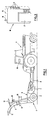
- the agricultural machine shown in Figure 1 is a basically conventional pull-type forage harvester 1 having a base frame, a pair of ground wheels 2, a drawbar 3 which is shown hitched to a 'towing tractor 4, and a drive shaft 5 which is shown connected to the power-take-off shaft of the tractor.
- the forage harvester further comprises a crop pickup unit 7 which is movable generally vertically between a raised, transport position and a lowered, operative position, a chopper unit indicated generally at 8 but not seen in any detail, reversible feeder means, equally not shown and a crop discharge spout 9 connected to the outlet of the chopper unit and having the usual deflector 11 at its discharge end.
- the discharge spout 9 is fitted with a swivel control 12 for moving the spout in azimuth, a vertical control 13 for moving the spout vertically, and a deflector control 14for moving the deflector 11.
- the forage harvester is fitted with a wireless remote control means including, on the one hand, a first control unit 16 mountable within the tractor cab and comprising a transmitter for transmitting encoded command signals and, on the other hand, a further control unit 15 mounted on the forage harvester and comprising a receiver and actuator for receiving encoded command signals from the transmitter and for actuating machine components in accordance with said command signals.
- the further control unit 15 including the receiver and actuator is mounted on the machine via antivibration mounts.
- the encoded signals preferably are of the infra-red type in as much as such signals penetrate through the cab window.
- the first control unit 16 is of the conventional hand held type and, as shown in greater detail in Figure 3, comprises four control buttons 17, a rangechange button 18, and a transmission window 19. For as long as a control button 17 is depressed, the controller transmits an encoded signal through the window 19 and, provided the window is directed generally towards the further control unit 15 on the forage harvester, then the transmitted signal will be received thereby. If the rangechange button 18 is depressed, then a further four differently encoded signals are available via the control buttons 17.
- a permanent magnet 21 is attached to the housing of the first control unit 16 in such a position as not to interfere with any of the inductance devices forming part of the transmitter. The magnet 21 allows the controller to be attached to a metallic part of the tractor cab convenient to the operator.
- FIG. 2 shows a circuit diagram of the further control unit 15 which comprises a decoder 22 which decodes each received signal and outputs the decoded signal on the appropriate one of output lines 23 to 30.
- the decoded signal is amplified by an amplifier 31; all amplifiers being shown as a single block; and the amplified signal sent on the appropriate one of eight output lines 32 to 39 connected to respective relays 41 to 48.
- the outputs 49 from the relays 41 to 48 are taken to connector 51 to which the motor or other actuator connections (not shown) and the battery connections (also not shown) are also taken.
- Each motor or actuator has two relays associated therewith in order that operation in one direction or another can be commanded to effect raising or lowering, or right-hand or left-hand movement of the component being controlled, as appropriate. If a component to be controlled is single acting, such as an electromagnetic clutch, for example, then only one of the two relays allocated thereto is employed, it being convenient to provide a standard further control unit 15 with the maximum number of relays.
- the further control unit 15 is also fitted with four doublethrow switches 52 to 55 which can be used to energise any of the eight relays 41 to 48 and thus control any of the components of the forage harvester connected to the further control 'unit 15.
- the switches 52 to 55 e.g. can be used to override the first control unit 16 for test purposes .and can be used in a diagnostic role. It should be noted that the switches 52 to 55 are not essential to the operation of the present invention and may be omitted.
- the discharge spout swivel control motor 12 is connected to the relays 41 and 42 which in turn are connected to the decoder 22 via control channels represented by the output lines 32, 33 and 23, 24.
- the encoded command signal will be transmitted through the window 19 to the further control unit 15 (provided the window is directed thereat) and the decoder 22 will decode that signal and output it on line 23 to the amplifier 31.
- the signal is then amplified and sent on output line 32 to the relay 41 which is thus energised and delivers the command signal to the swivel control 12 via the associated output line 49 and connector 51.
- the spout 9 will be moved to the right for as long as the appropriate control button 17 is depressed. Movement to the left is effected by depressing a different button 17 to generate a differently encoded command signal which is encoded as before but this time sent on output line 24 to the amplifier 31 and thence on output line 33 to the relay 42.
- Control of the other components is effected in a generally similar manner, including the direction of rotation of the reversible feeder means to the chopper unit 8.
- the present invention affords a very simple and very effective apparatus and method for controlling the operation of an agricultural machine such as a forage harvester without involving cumbersome cabling connecting the machine to the towing vehicle and thus avoiding structural modification of the latter to accept the cabling.
- the machine can be controlled other than from within the towing vehicle, should this be necessary, by the operator taking the first control unit 16 from the tractor cab and operating it from any desired position, provided there is a direct "line of sight" from the first control unit to the further control unit 15.
- the invention can be adapted to any pull-type machine: for example, it can be used with a pull-type round baler in which the drawbar, the tailgate and the twine-wrapping mechanism will normally be controlled. It can also be used with a pull-type combine harvester to control, respectively monitor the numerous functions of such a machine.
- the present invention also covers the possibility of monitoring a harvesting machine as regards a harvesting or crop condition and/or a characteristic of one or more components, which characteristic may be associated with component wear, for example.
- the feeder means to the chopper unit 8 could be provided with a sensor which will produce an output signal indicative of whether the drive is in the forward or reverse mode, and the pick-up unit 7 may be provided to indicate whether the unit is in the raised, transport position or the lowered, operative position.
- the sensor output signals would be encoded and transmitted to a receiver in the tractor cab which will decode the signals and perhaps display the conditions represented thereby.
Landscapes
- Life Sciences & Earth Sciences (AREA)
- Environmental Sciences (AREA)
- Agricultural Machines (AREA)
Description
- This invention relates to pull-type or towable agricultural machines of the type as specified in the preamble of claim 1 and which thus, in use, are hitched to a towing vehicle such as a tractor and which are equiped for wireless remote control from said tractor.
- With pull-type machines having components which have to be controlled from the towing vehicle certain disadvantages arise, one of which is that control cables have to be taken from the controls located in the cab of the towing vehicle to a connector on the towing vehicle which receives a complementary connector attached to cables leading to the components to be controlled on the agricultural machine. Cabling is cumbersome and furthermore also relatively expensive and, when installed on the towing vehicle, it is necessary to drill the cab structure for the through passage of the cables which can be detrimental to the sound- proofing which is installed in modern vehicles such as tractors. Another disadvantage is that if a farmer has a plurality of pull-type machines, then it is likely that he will need the same number of controls, connectors and sets of cabling in view of the different forms of control required for the various machines. In as much as there is a practical limit to the controls and cabling which can be accomodated in a given cab, it often happens that a farmer is restricted to one tractor fitted out to tow and control one machine, and another tractor fitted out to tow and control another machine, it would be far more convenient if any tractor or other vehicle could tow and control any machine.
- Alternatively the control box of a given pull-type machine may be coupled without the use of any connectors via a flexible cable string to the machine components to be controlled. Such a control box is suited to be attached to a support within the tractor cab with the cable string passing through e.g. a cab window which therefore has to be opened and left open during the operation of the machine. Obviously, this is even more detrimental to the sound proofing of the cab and further adversely affects the air conditioning within the cab and permits the ingress of dirt.
- Remote control means of the type as considered herebefore and for use in conjunction with pull-type agricultural machines have been described in DE-A-1.632.824. This document further also describes, in general terms, wireless remote controls for controlling a plurality of functions of a pull-type agricultural machine. To this end, a transmitter, capable of transmitting electro-magnetic signals, is provided on the tractor means and a receiver, capable of receiving said electromagnetic signals is mounted on the agricultural machine. Different frequencies are used for distinguishing between the various command signals. The receiving means are operable, in response to the command signals received from the transmitter means, to actuate the appropriate actuator means associated with the machine components to be controlled.
- The wireless remote control means as disclosed in DE-A-1.632.824 are plagued with a plurality of shortcomings and drawbacks, especially when used on pull-type agricultural machines operated in combination with modern towing tractor means equiped with cabs enclosing the operator station ' thereof.
- It is the objective of the present invention to overcome these shortcomings and drawbacks of known pull-type agricultural machines equiped with remote controls. More specifically it is the objective to provide pull-type agricultural machi- nary with wireless remote controls which can be utilized for controlling various machine components from within the cab of a modern tractor in an efficient manner and without being troubled with interferences of any kind.
- This objective is accomplished with an agricultural machine which is equiped with a wireless remote control as specified in the claims attached hereto.
- The remote control and/or monitoring of pull-type agricultural machinery which, in accordance with the present invention uses transmitter and receiver means capable of transmitting and receiving encoded signals, is advantageous in many respects. Indeed, it not only enables wireless remote control and/or monitoring, which in itself is already a major step forward, but it also enables the remote control and/or monitoring of a plurality of machine functions without any interference therebetween. Furthermore, the use of encoded signals enables remote controls and/or monitoring in widely varying environmental conditions (darkness, dark weather conditions, dirty cab, windows, abundant sunshine....) and without suffering from any stray signals (abundant sunshine, citizen band radio signals....).
- An agricultural machine in accordance with the present invention will now be described in greater detail, by way of example, with reference to the accompanying drawings, in which:
- Fig 1 is a side view of the machine,
- Fig 2 is an electrical circuit diagram, and
- Fig 3 is a perspective view of a controller for controlling the machine of Figure 1.
- The agricultural machine shown in Figure 1 is a basically conventional pull-type forage harvester 1 having a base frame, a pair of ground wheels 2, a
drawbar 3 which is shown hitched to a 'towing tractor 4, and a drive shaft 5 which is shown connected to the power-take-off shaft of the tractor. The forage harvester further comprises acrop pickup unit 7 which is movable generally vertically between a raised, transport position and a lowered, operative position, a chopper unit indicated generally at 8 but not seen in any detail, reversible feeder means, equally not shown and a crop discharge spout 9 connected to the outlet of the chopper unit and having the usual deflector 11 at its discharge end. The discharge spout 9 is fitted with a swivel control 12 for moving the spout in azimuth, avertical control 13 for moving the spout vertically, and a deflector control 14for moving the deflector 11. - In accordance with the present invention, the forage harvester is fitted with a wireless remote control means including, on the one hand, a
first control unit 16 mountable within the tractor cab and comprising a transmitter for transmitting encoded command signals and, on the other hand, afurther control unit 15 mounted on the forage harvester and comprising a receiver and actuator for receiving encoded command signals from the transmitter and for actuating machine components in accordance with said command signals. Thefurther control unit 15 including the receiver and actuator is mounted on the machine via antivibration mounts. The encoded signals preferably are of the infra-red type in as much as such signals penetrate through the cab window. Other signals such as ultrasonic signals are less- suitable in as much as such signals do not penetrate through the cab windows and thus would necessitate the installation of thefirst control unit 16 including the transmitter outside the tractor cab which is undesirable. Thefirst control unit 16 is of the conventional hand held type and, as shown in greater detail in Figure 3, comprises fourcontrol buttons 17, arangechange button 18, and atransmission window 19. For as long as acontrol button 17 is depressed, the controller transmits an encoded signal through thewindow 19 and, provided the window is directed generally towards thefurther control unit 15 on the forage harvester, then the transmitted signal will be received thereby. If therangechange button 18 is depressed, then a further four differently encoded signals are available via thecontrol buttons 17. Apermanent magnet 21 is attached to the housing of thefirst control unit 16 in such a position as not to interfere with any of the inductance devices forming part of the transmitter. Themagnet 21 allows the controller to be attached to a metallic part of the tractor cab convenient to the operator. - Figure 2 shows a circuit diagram of the
further control unit 15 which comprises adecoder 22 which decodes each received signal and outputs the decoded signal on the appropriate one ofoutput lines 23 to 30. The decoded signal is amplified by anamplifier 31; all amplifiers being shown as a single block; and the amplified signal sent on the appropriate one of eightoutput lines 32 to 39 connected torespective relays 41 to 48. The outputs 49 from therelays 41 to 48 are taken toconnector 51 to which the motor or other actuator connections (not shown) and the battery connections (also not shown) are also taken. Each motor or actuator has two relays associated therewith in order that operation in one direction or another can be commanded to effect raising or lowering, or right-hand or left-hand movement of the component being controlled, as appropriate. If a component to be controlled is single acting, such as an electromagnetic clutch, for example, then only one of the two relays allocated thereto is employed, it being convenient to provide a standardfurther control unit 15 with the maximum number of relays. - The
further control unit 15 is also fitted with four doublethrow switches 52 to 55 which can be used to energise any of the eightrelays 41 to 48 and thus control any of the components of the forage harvester connected to the further control 'unit 15. The switches 52 to 55 e.g. can be used to override thefirst control unit 16 for test purposes .and can be used in a diagnostic role. It should be noted that the switches 52 to 55 are not essential to the operation of the present invention and may be omitted. - To illustrate the operation of the invention it will be assumed that the discharge spout swivel control motor 12 is connected to the
relays decoder 22 via control channels represented by theoutput lines button 17 on thefirst control unit 16 appropriate to say swivelling of the discharge spout 9 to the right, the encoded command signal will be transmitted through thewindow 19 to the further control unit 15 (provided the window is directed thereat) and thedecoder 22 will decode that signal and output it online 23 to theamplifier 31. The signal is then amplified and sent onoutput line 32 to therelay 41 which is thus energised and delivers the command signal to the swivel control 12 via the associated output line 49 andconnector 51. Thus the spout 9 will be moved to the right for as long as theappropriate control button 17 is depressed. Movement to the left is effected by depressing adifferent button 17 to generate a differently encoded command signal which is encoded as before but this time sent onoutput line 24 to theamplifier 31 and thence onoutput line 33 to therelay 42. Control of the other components is effected in a generally similar manner, including the direction of rotation of the reversible feeder means to the chopper unit 8. - It will be seen that the present invention affords a very simple and very effective apparatus and method for controlling the operation of an agricultural machine such as a forage harvester without involving cumbersome cabling connecting the machine to the towing vehicle and thus avoiding structural modification of the latter to accept the cabling. Furthermore, the machine can be controlled other than from within the towing vehicle, should this be necessary, by the operator taking the
first control unit 16 from the tractor cab and operating it from any desired position, provided there is a direct "line of sight" from the first control unit to thefurther control unit 15. Incidentally, it should be noted that encoded infra-red signals transmitted from within the cab have been found to penetrate a cab window which is reasonable dirty whereby thefirst control unit 16 will be able to "see" thefurther control unit 15 if the operator can see the machine which he normally needs to do in order to monitor the performance thereof. - It will be appreciated that the invention can be adapted to any pull-type machine: for example, it can be used with a pull-type round baler in which the drawbar, the tailgate and the twine-wrapping mechanism will normally be controlled. It can also be used with a pull-type combine harvester to control, respectively monitor the numerous functions of such a machine.
- The present invention also covers the possibility of monitoring a harvesting machine as regards a harvesting or crop condition and/or a characteristic of one or more components, which characteristic may be associated with component wear, for example. In the illustrated embodiment, for example, the feeder means to the chopper unit 8 could be provided with a sensor which will produce an output signal indicative of whether the drive is in the forward or reverse mode, and the pick-
up unit 7 may be provided to indicate whether the unit is in the raised, transport position or the lowered, operative position. The sensor output signals would be encoded and transmitted to a receiver in the tractor cab which will decode the signals and perhaps display the conditions represented thereby.
Claims (6)
Applications Claiming Priority (2)
| Application Number | Priority Date | Filing Date | Title |
|---|---|---|---|
| GB848402548A GB8402548D0 (en) | 1984-01-31 | 1984-01-31 | Controlling/monitoring agricultural machines |
| GB8402548 | 1984-01-31 |
Publications (3)
| Publication Number | Publication Date |
|---|---|
| EP0150887A2 EP0150887A2 (en) | 1985-08-07 |
| EP0150887A3 EP0150887A3 (en) | 1985-08-28 |
| EP0150887B1 true EP0150887B1 (en) | 1990-05-02 |
Family
ID=10555831
Family Applications (1)
| Application Number | Title | Priority Date | Filing Date |
|---|---|---|---|
| EP19850200086 Expired EP0150887B1 (en) | 1984-01-31 | 1985-01-28 | Remote controlled agricultural machine |
Country Status (3)
| Country | Link |
|---|---|
| EP (1) | EP0150887B1 (en) |
| DE (1) | DE3577383D1 (en) |
| GB (1) | GB8402548D0 (en) |
Families Citing this family (2)
| Publication number | Priority date | Publication date | Assignee | Title |
|---|---|---|---|---|
| NL8501552A (en) * | 1985-05-30 | 1986-12-16 | Multinorm Bv | COMMUNICATION SYSTEM. |
| DE10228880B4 (en) * | 2002-06-27 | 2005-09-08 | Jakob Voets Ing. Grad. Gmbh & Co. Kg Rheinische Landschaftspflege | Mowing device for lawn and landscape meadow maintenance with a device for receiving and shredding crops |
Family Cites Families (5)
| Publication number | Priority date | Publication date | Assignee | Title |
|---|---|---|---|---|
| DE1632824A1 (en) * | 1968-02-20 | 1970-12-10 | Koedel & Boehm Gmbh | Remote control for tractor-drawn agricultural machines, such as forage harvesters, combine harvesters, pick-up presses, etc. |
| US4031963A (en) * | 1975-04-14 | 1977-06-28 | Erhard Poggemiller | Depth control device for ground working agricultural implements |
| DE2807887A1 (en) * | 1978-02-20 | 1979-08-30 | Alusuisse | Carbon anodes baking furnace measurement and control system - uses modulated radio signals transmitted to and from stationary controller |
| US4376609A (en) * | 1980-03-31 | 1983-03-15 | Sperry Corporation | Automatic spout control for agricultural machines |
| DE70340T1 (en) * | 1981-07-16 | 1983-09-15 | Deere & Co., 61265 Moline, Ill. | CONTROL OF THE EJECTOR FOR FIELD CHOPPER. |
-
1984
- 1984-01-31 GB GB848402548A patent/GB8402548D0/en active Pending
-
1985
- 1985-01-28 EP EP19850200086 patent/EP0150887B1/en not_active Expired
- 1985-01-28 DE DE8585200086T patent/DE3577383D1/en not_active Expired - Lifetime
Also Published As
| Publication number | Publication date |
|---|---|
| EP0150887A2 (en) | 1985-08-07 |
| GB8402548D0 (en) | 1984-03-07 |
| DE3577383D1 (en) | 1990-06-07 |
| EP0150887A3 (en) | 1985-08-28 |
Similar Documents
| Publication | Publication Date | Title |
|---|---|---|
| CA2123340C (en) | Wireless snow plow control system | |
| US7142098B2 (en) | Wireless data transfer system for a tractor-trailer | |
| US5880684A (en) | Operator device | |
| US20030139177A1 (en) | Method and apparatus for the remote control of an operating table | |
| EP0755127A3 (en) | CDMA diversity transmission system | |
| CA2841221C (en) | Work vehicle hvac control based on operator seat direction | |
| CA1305241C (en) | Agricultural tractor communication system | |
| AU2002356769A1 (en) | Monitoring and control device for an articulated lorry with remote-controllable fifth wheel | |
| US6971225B1 (en) | Control arrangement for a pull-type windrow merger | |
| JPH10105860A (en) | Communication system | |
| EP0150887A2 (en) | Remote controlled agricultural machine | |
| CA2186495A1 (en) | Hands-free two-way radio communication system | |
| US5074373A (en) | Drive connection on a support vehicle | |
| EP1306278B1 (en) | Control device for a driving school vehicle and affiliated driving instructor post | |
| EP1348207A1 (en) | Universal remote control device | |
| DE3172707D1 (en) | Spout control for a forage harvester | |
| JP2002345058A (en) | Work machine remote control device | |
| US6476778B1 (en) | Remotely controlled retractable power antenna | |
| KR101858401B1 (en) | Remote control unit and remote control method capable of setting a drive of actuator | |
| CN212148792U (en) | Automatic brake device of tractor | |
| JPH06165609A (en) | Farm tractor | |
| JPH08279778A (en) | Remote control method and device for construction vehicle | |
| CN219603094U (en) | Intelligent remote control system for travelling crane | |
| GB2172086A (en) | Drive line for transmitting power from a tractor to an implement pulled by the tractor | |
| DE19618033A1 (en) | Automative agricultural machine remote control |
Legal Events
| Date | Code | Title | Description |
|---|---|---|---|
| PUAI | Public reference made under article 153(3) epc to a published international application that has entered the european phase |
Free format text: ORIGINAL CODE: 0009012 |
|
| PUAL | Search report despatched |
Free format text: ORIGINAL CODE: 0009013 |
|
| 17P | Request for examination filed |
Effective date: 19850128 |
|
| AK | Designated contracting states |
Designated state(s): DE FR GB |
|
| AK | Designated contracting states |
Designated state(s): DE FR GB |
|
| RAP1 | Party data changed (applicant data changed or rights of an application transferred) |
Owner name: NEW HOLLAND N.V. |
|
| 17Q | First examination report despatched |
Effective date: 19870703 |
|
| RAP3 | Party data changed (applicant data changed or rights of an application transferred) |
Owner name: FORD NEW HOLLAND N.V. |
|
| GRAA | (expected) grant |
Free format text: ORIGINAL CODE: 0009210 |
|
| AK | Designated contracting states |
Kind code of ref document: B1 Designated state(s): DE FR GB |
|
| REF | Corresponds to: |
Ref document number: 3577383 Country of ref document: DE Date of ref document: 19900607 |
|
| ET | Fr: translation filed | ||
| PGFP | Annual fee paid to national office [announced via postgrant information from national office to epo] |
Ref country code: FR Payment date: 19910111 Year of fee payment: 7 |
|
| PGFP | Annual fee paid to national office [announced via postgrant information from national office to epo] |
Ref country code: GB Payment date: 19910121 Year of fee payment: 7 |
|
| PLBI | Opposition filed |
Free format text: ORIGINAL CODE: 0009260 |
|
| PGFP | Annual fee paid to national office [announced via postgrant information from national office to epo] |
Ref country code: DE Payment date: 19910208 Year of fee payment: 7 |
|
| 26 | Opposition filed |
Opponent name: AMAZONEN-WERK H. DREYER GMBH & CO. KG Effective date: 19910130 |
|
| RDAG | Patent revoked |
Free format text: ORIGINAL CODE: 0009271 |
|
| STAA | Information on the status of an ep patent application or granted ep patent |
Free format text: STATUS: PATENT REVOKED |
|
| 27W | Patent revoked |
Effective date: 19910930 |
|
| GBPR | Gb: patent revoked under art. 102 of the ep convention designating the uk as contracting state |