EP0150113B1 - Co-axial cable stripping tool and end portion preparation method - Google Patents
Co-axial cable stripping tool and end portion preparation method Download PDFInfo
- Publication number
- EP0150113B1 EP0150113B1 EP85300352A EP85300352A EP0150113B1 EP 0150113 B1 EP0150113 B1 EP 0150113B1 EP 85300352 A EP85300352 A EP 85300352A EP 85300352 A EP85300352 A EP 85300352A EP 0150113 B1 EP0150113 B1 EP 0150113B1
- Authority
- EP
- European Patent Office
- Prior art keywords
- tool
- blade
- cut
- layer
- cable
- Prior art date
- Legal status (The legal status is an assumption and is not a legal conclusion. Google has not performed a legal analysis and makes no representation as to the accuracy of the status listed.)
- Expired
Links
Images

Classifications
-
- H—ELECTRICITY
- H02—GENERATION; CONVERSION OR DISTRIBUTION OF ELECTRIC POWER
- H02G—INSTALLATION OF ELECTRIC CABLES OR LINES, OR OF COMBINED OPTICAL AND ELECTRIC CABLES OR LINES
- H02G1/00—Methods or apparatus specially adapted for installing, maintaining, repairing or dismantling electric cables or lines
- H02G1/12—Methods or apparatus specially adapted for installing, maintaining, repairing or dismantling electric cables or lines for removing insulation or armouring from cables, e.g. from the end thereof
- H02G1/1202—Methods or apparatus specially adapted for installing, maintaining, repairing or dismantling electric cables or lines for removing insulation or armouring from cables, e.g. from the end thereof by cutting and withdrawing insulation
- H02G1/1204—Hand-held tools
- H02G1/1221—Hand-held tools the cutting element rotating about the wire or cable
- H02G1/1224—Hand-held tools the cutting element rotating about the wire or cable making a transverse cut
-
- Y—GENERAL TAGGING OF NEW TECHNOLOGICAL DEVELOPMENTS; GENERAL TAGGING OF CROSS-SECTIONAL TECHNOLOGIES SPANNING OVER SEVERAL SECTIONS OF THE IPC; TECHNICAL SUBJECTS COVERED BY FORMER USPC CROSS-REFERENCE ART COLLECTIONS [XRACs] AND DIGESTS
- Y10—TECHNICAL SUBJECTS COVERED BY FORMER USPC
- Y10T—TECHNICAL SUBJECTS COVERED BY FORMER US CLASSIFICATION
- Y10T29/00—Metal working
- Y10T29/49—Method of mechanical manufacture
- Y10T29/49002—Electrical device making
- Y10T29/49117—Conductor or circuit manufacturing
- Y10T29/49123—Co-axial cable
Definitions
- This invention relates to a tool suitable for preparing the end portion of an elongate member having a core and at least three layers therearound, by stripping the layers back to expose the core and other layers from the end of the member.
- the invention further relates to a method for preparing the end portion of such a member.
- the invention relates to a tool specifically intended to assist the preparation of the end portion of an electric co-axial cable to permit the electrical termination thereof, for example by a jointing technique or by the attachment thereto of a co- axial cable connector, and also relates to a method specifically intended to prepare such an electric co-axial cable, successively to expose the core and overlying layers, from the end of the cable.
- the tool and method of this invention may be used to strip layers from multi-layered elongate members other than electric co-axial cables, it will in the following be described with specific reference to electric co-axial cables. However, it will be appreciated that the tool and method do have other applications - for instance, the preparation of end portions of fibre optic cables - and the term "co-axial cable" as used herein should be construed accordingly.
- a typical electric co-axial cable has three layers around a central conducting core namely, an insulating first layer, a conducting second layer and an insulating third layer or outer sheath. Any of these layers may be formed as a group of two or more distinct sub-layers for example, the conducting second layer may comprise a first sub-layer of copper foil wrapped around the insulating first layer and a second sub-layer of braided copper strands laid over the copper foil; and the insulating third layer may comprise two or more sub-layers in order to impart to the completed cable the required electrical and mechanical properties.
- the invention is of course applicable to such multi-layered cables, and a reference hereinafter to any particular layer of a cable is intended to apply equally to a group of layers, where such a group serves the function of a single layer and so should be removed as a single layer when preparing the end portion of the cable.
- GB-A-1164544 There have been designed various tools to assist the stripping of insulation from cables; one such tool is described in GB-A-1164544.
- This tool has a body with a bore through which the cable is passed, and a cutting blade adjustably mounted on the body and arranged to cut into the insulation of the cable on rotation of the tool about the cable.
- the tool must however carefully be adjusted before a stripping operation is commenced to cut into the cable to an exact depth; the tool is therefore not suitable for use with multi-layer cables where the preparation of the end portion requires several cuts to be made, to different depths.
- This tool has a body defining three separate cable-receiving openings each of which has an individual blade associated therewith adjustably mounted on the body. Before the tool can be used to prepare the end portion of a coaxial cable, all three blades must separately be pre-set to cut to the required depth. A cable is stripped by being positioned successively in the three openings, a cut being made in the cable in each opening, by rotating the tool around the cable.
- an outer layer e.g. the outer insulating. layer of a co-axial cable
- the outer conductor and the inner insulating layer of a co-axial cable e.g. the outer conductor and the inner insulating layer of a co-axial cable
- Configuring the tool to suit a particular cable enables the tool to be used su ' ccessively to expose the core and each overlying layer of the cable even though the tool effects only two different depths of cut. This is obtained by having the deeper cut only partially severing the insulating first layer of the cable, over the core.
- a first deep cut is made adjacent the end of the cable by rotating the tool around the cable in the appropriate sense, whereafter the severed outer layers are rotated around the core with respect to the remainder of the cable, so completely separating the first layer whilst leaving the core intact.
- the tool is then moved further on the cable and a second deep cut made, but the outer layers are not subsequently rotated around the core.
- a second aspect of this invention provides a method for preparing the end portion of an elongate member having a core and at least three coaxial layers therearound so as successively to expose the core and layers from the end of the member, which method comprises:
- the blade conveniently has a mounting hole by means of which the blade is pivoted to a pin provided on the tool body (or carrier, if provided).
- the blade may then have a second hole, preferably in the form of an elongate slot, through which a second pin passes with clearance, the pivoting movement of the blade being limited by interengagement of one or the other sides of the second hole with the second pin.
- the tool includes guide means assisting the positioning of the tool with respect to a cable.
- guide means may comprise a projection from the tool body adjacent the opening and having graduations or other indexes for alignment with the cable end or an annular cut already formed therein.
- the cutting blade may be set relative to the body at a slight angle to a strict radial plane of a cable located in the opening, whereby rotation of the tool around the coaxial cable in the sense causing the blade to effect a shallow cut causes the body to be threaded along the cable, whilst at the same time at least partially severing the outer insulating layer.
- the severed outer layerthus is in the form of a helicoid, at the completion of the severing operation, and may with great facility be removed from the cable simply by pulling the free end portion of the helicoid in an axial direction. Rotation of the tool in the other sense around the cable, to sever all of the layers except the inner core, should not cause axial movement of the tool along the length of the cable, in view of the considerably great depth of penetration of the cutting blade.
- the body of the tool may suitably be profiled to lend itself to the ready rotation thereof around a coaxial cable.
- the body or the blade carrier (if provided) may include a rounded finger hole.
- the blade may be pivoted directly to the body and be appropriately profiled to permit the application of a force thereto to drive the blade - and hence the body- around the co-axial cable to be prepared. In such a case the same severing action can be obtained, because the body will tend to trail behind the rotation of the blade, owing to the friction between the body and the cable, so following the rotation of the blade in whichever sense a rotative force is given to the blade.
- the method of this invention as described above stems from the realisation that the first layer over the core, when partially severed by a radial cut therearound, can thereafter be completely separated from the major part of that layer by twisting the partially severed portion about the core, so permitting the subsequent removal of that layer, or can be left to remain connected to the major part of that layer, if subjected just to an axial force through the overlying layers.
- the depth of cut required to achieve reliable separation on twisting, but sufficient strength to hold the partially-severed portion to the major part when axial force alone is applied depends upon the particular materials of the cable as well as the dimensions of the cable, but tests have shown the cut should sever the first layer to a depth in the range of from 20% to 50% of the first layer thickness, and preferably about 30% of that thickness.
- the depth of the third cut should be great enough to sever the third layer to an extent sufficient to ensure that layer will separate on applying an axial force to that layer, but it is preferred for the third cut to stop short of the conducting second layer, to avoid risk of "nicking" that layer.
- This third layer may thus be severed to a depth of from 60% to 90% of that layer thickness, but preferably to a depth of about 75% of the layer thickness, to ensure the second layer is not affected by the cut, even with cables constructed with relatively low concentricity tolerances.
- the tool is configured to provide a guide for the positioning of the cuts. This may be achieved by a graduated projection, enabling the operator to determine exactly where to position the cable with respect to the tool, prior to effecting a cut.
- the main body 11 has a side plate 14 from which a generally U-shaped wall 15 upstands, leaving a flange 16 projecting beyond the U-shaped wall. In association with the side plate 14, the inner faces of the wall 15 define the slot 17 within which a generally rectangular portion of the blade carrier 13 may slide.
- the moulding of the main body 11 may include recesses 18, to reduce the amount of plastics material employed and also to permit satisfactory production of the part by an injection moulding process, taking into account material shrinkage.
- the blade carrier 13 has a finger portion 29 including a finger hole 30 and a moulding recess 31 in which may be provided, for example, information concerning the particular sizing of the tool.
- a blade portion 32 Projecting from the finger portion 29 is a blade portion 32, adapted for sliding movement within the slot 17 defined by the main body 11.
- the top face 33 of this portion 32 is provided with a semi-circular groove 34, centrally positioned for alignment with the bore 22 in the main body 11.
- the tool is completed by means of a resilient endless band 41 passed around the U-shaped wall 15, between the flanges 16 and 19, and around the finger portion 29 of the blade carrier 13.
- the band 41 should be in a state of tension, so that it holds the blade carrier 13 fully engaged in the slot in the main body 11.
- finger and thumb friction grip portions 42 and 43 are provided respectively on the side plate 14 and cover plate 12.
- the guide surfaces 27 and 28 may be used to assist the preparation of a cable end portion with exposed layers of different lengths, by positioning an already-formed annular cut part-way between the surfaces; rather than aligned therewith.
- the blade need not immediately penetrate the cable to the required depth.
- the severing action may be gradual, as the tool is rotated, with the band 41 gradually drawing the blade into the cable to the predetermined depth, as tool rotation is continued.
- the operation of the tool is fully automatic in that the blade moves to either one of its two positions by virtue of the drag of the blade through the cable, depending on whether the tool is rotated clockwise or counter- clockwise.
- Modification of the tool to suit different cables is relatively simple. Identical mouldings may be used, with the bores 22 and 25, and the grooves 24 and 34 appropriately machined to suit the cable with which the tool is to be used. Moreover, the holes in the carrier to receive the pins 35 and 36 may be jig-drilled at appropriate positions to give the required two depths of cut for any given cable.
- Step I of the method comprises making an annular cut 114 (for example with the tool of Figures 1 to 4, or with the tool of Figure 6, described below) in a radial plane fully around the cable to a first depth sufficient partially to sever the first layer 111.
- the first cut may lie for example approximately 14 mm from the end of the cable and in the case of a typical electric co- axial cable, may penetrate the first layer 111 to a depth of approximately 50% of the radial thickness of that layer.
Description
- This invention relates to a tool suitable for preparing the end portion of an elongate member having a core and at least three layers therearound, by stripping the layers back to expose the core and other layers from the end of the member. The invention further relates to a method for preparing the end portion of such a member. In particular, but not exclusively, the invention relates to a tool specifically intended to assist the preparation of the end portion of an electric co-axial cable to permit the electrical termination thereof, for example by a jointing technique or by the attachment thereto of a co- axial cable connector, and also relates to a method specifically intended to prepare such an electric co-axial cable, successively to expose the core and overlying layers, from the end of the cable.
- Though the tool and method of this invention may be used to strip layers from multi-layered elongate members other than electric co-axial cables, it will in the following be described with specific reference to electric co-axial cables. However, it will be appreciated that the tool and method do have other applications - for instance, the preparation of end portions of fibre optic cables - and the term "co-axial cable" as used herein should be construed accordingly.
- A typical electric co-axial cable has three layers around a central conducting core namely, an insulating first layer, a conducting second layer and an insulating third layer or outer sheath. Any of these layers may be formed as a group of two or more distinct sub-layers for example, the conducting second layer may comprise a first sub-layer of copper foil wrapped around the insulating first layer and a second sub-layer of braided copper strands laid over the copper foil; and the insulating third layer may comprise two or more sub-layers in order to impart to the completed cable the required electrical and mechanical properties. The invention is of course applicable to such multi-layered cables, and a reference hereinafter to any particular layer of a cable is intended to apply equally to a group of layers, where such a group serves the function of a single layer and so should be removed as a single layer when preparing the end portion of the cable.
- The stripping of the end portion of an electric co-axial cable to prepare it ready for termination presents considerably greater problems than those encountered in preparing a conventional single conductor wire. In a manufacturing concern, such problems may be overcome by appropriate automated machinery which is both complex and relatively expensive. However, for on-site installation of co-axial cables, or for relatively small scale users of such cables, the use of automated machinery is not appropriate and the preparation of an end portion of a co-axial cable can present certain problems. The usual manual method of preparing the end portion of a co-axial cable is by using a sharp hand-held knife and a plier-like wire stripper. Though adequate stripping may be performed, the conductors often are accidentally "nicked", and there is the risk that the operator may inflict a serious wound on himself, by using an open sharp knife blade.
- There have been designed various tools to assist the stripping of insulation from cables; one such tool is described in GB-A-1164544. This tool has a body with a bore through which the cable is passed, and a cutting blade adjustably mounted on the body and arranged to cut into the insulation of the cable on rotation of the tool about the cable. The tool must however carefully be adjusted before a stripping operation is commenced to cut into the cable to an exact depth; the tool is therefore not suitable for use with multi-layer cables where the preparation of the end portion requires several cuts to be made, to different depths.
- To overcome this problem, other tools have been proposed, such as that of US-A-4366619. This tool has a body defining three separate cable-receiving openings each of which has an individual blade associated therewith adjustably mounted on the body. Before the tool can be used to prepare the end portion of a coaxial cable, all three blades must separately be pre-set to cut to the required depth. A cable is stripped by being positioned successively in the three openings, a cut being made in the cable in each opening, by rotating the tool around the cable.
- It is a primary object of this invention to provide a tool suitable for preparing the end portion of an elongate multi-layer member and specifically an electric co-axial cable, which tool is very simple to use and yet is able reliably and consistently to cut selectively through either only an outer layer (e.g. the outer insulating. layer of a co-axial cable) or more than just the outer layer (e.g. the outer insulating layer, the outer conductor and the inner insulating layer of a co-axial cable), without also cutting the inner conductor.
- According to a first aspect of this invention, there is provided a tool suitable for stripping distinct layers from a multi-layer member, which tool comprises a body defining an opening for receiving the member to be stripped, a cutting blade having a cutting edge, and a pin pivotally mounting the cutting blade on the body so that the cutting edge extends generally across and projecting into the opening, which tool is characterised in that stop means are provided to limit the free pivoting movement of the cutting blade in both the clockwise and the counter-clockwise senses about the pivot pin, and in that the cutting blade is mounted on the pivot pin for free pivoting movement between limiting positions defined by the stop means, said stop means, being arranged so that when the cutting blade is located at one limiting position the cutting edge of the blade projects into the opening to a greater extent than when the cutting blade is located at the other limiting position, the movement of the cutting blade to either one of its two said limiting positions being caused by rotation of the tool about the member to be stripped during a stripping operation and depending upon the sense of rotation thereabout.
- The following further description of this invention will refer exclusively to electric co-axial cables, though it will be appreciated that many of the preferred features are applicable to tools intended for use with other elongate multi-layer members.
- When the tool of this invention is to be used with a co-axial cable, it must specifically be designed to match the cable configuration - but since such cables come in a relatively few number of sizes, this need not present a significant disadvantage. The arrangement of the tool is such that when it is desired to expose the inner conductor of a co-axial cable, the tool is suitably positioned on the cable and is rotated therearound in one sense, whereby frictional drag on the blade causes the blade to move to its first limiting position so severing all the layers over the core conductor though the layer immediately overlying the core may only partially be severed, radially. Then the tool is again suitably positioned on the cable at the point where the outer conductor is to be exposed, and the tool is moved therearound in the opposite sense, so causing the blade to move to its other position where the cutting edge severs only the outer insulating layer. Stripping of the severed layers may thereafter easily be accomplished.
- Configuring the tool to suit a particular cable enables the tool to be used su'ccessively to expose the core and each overlying layer of the cable even though the tool effects only two different depths of cut. This is obtained by having the deeper cut only partially severing the insulating first layer of the cable, over the core. To do this, a first deep cut is made adjacent the end of the cable by rotating the tool around the cable in the appropriate sense, whereafter the severed outer layers are rotated around the core with respect to the remainder of the cable, so completely separating the first layer whilst leaving the core intact. The tool is then moved further on the cable and a second deep cut made, but the outer layers are not subsequently rotated around the core. Next the tool is moved yet further on the cable and a third cut made, but this time by rotating the tool in the opposite sense so causing the blade to move to its other position and so effecting a shallow cut through the outer layer only. Preparation is completed by pulling the tool off the cable whilst leaving the blade in the third cut, which action slides the severed layers off the end portion of the cable, so successively exposing the conducting second layer, the first insulating layer and the conducting core.
- In view of the foregoing, it is a second object of this invention to provide a method for the preparation of the end portion of a co-axial cable which method can be performed by a simple device but which method permits adequate cutting of the layers to enable the removal thereof, without risk of damage to the core.
- Accordingly, a second aspect of this invention provides a method for preparing the end portion of an elongate member having a core and at least three coaxial layers therearound so as successively to expose the core and layers from the end of the member, which method comprises:
- a) effecting a first cut around the member at a position adjacent but spaced from the end of the member to a depth sufficient partially to sever the layer immediately overlying the core;
- b) twisting the so-severed layers around the core so as to complete separation of the end portion of the layer immediately overlying the core from the major portion thereof;
- c) effecting a second cut around the member at a position spaced further from the end of the member than the first cut and to the same depth as was effected the first cut;
- d) effecting a third cut around the member at a position spaced further from the end of the member than the second cut but to a lesser depth sufficient at least partially to sever the third layer overlying the second layer but not to sever that second layer;
- e) applying axially of the member and in the direction of the end thereof a force to the severed portion of the third layer at or immediately adjacent the third cut thereby to strip from the member successively from the third cut the third layer, the second layer and the first layer, so leaving an exposed length of the core at the end of the member.
- In performing the method of this invention, it will be appreciated that though three cuts are made around the cable, two cuts (the first and second cuts) are made to the same depth, and so a tool designed to perform this method may be much simplified in that it has to be capable of effecting only two different depths of cut. Moreover, by only partially severing the first layer with both the first and second cuts, there is no risk of damage to the central core by the cutting blade whilst at the same time guaranteeing a clean cut through the outer conductor, and so cables manufactured with even relatively poor concentric tolerances can successfully be prepared by this method.
- Preferably, the cutting blade of the tool of this invention is pivotally mounted on a carrier itself slidably mounted with respect to the body, whereby the blade may be moved clear of the opening by sliding movement of the carrier so facilitating the insertion of a cable into the opening. For such an arrangement, the opening may be in the form of a through-bore, in which 'the cable may be received. Advantageously, a resilient bias is provided between the carrier and body, to urge the blade towards the opening. This enables the blade progressively to penetrate the cable to the required depth as the tool is rotated around the cable.
- The blade conveniently has a mounting hole by means of which the blade is pivoted to a pin provided on the tool body (or carrier, if provided). The blade may then have a second hole, preferably in the form of an elongate slot, through which a second pin passes with clearance, the pivoting movement of the blade being limited by interengagement of one or the other sides of the second hole with the second pin.
- Preferably the tool includes guide means assisting the positioning of the tool with respect to a cable. Such guide means may comprise a projection from the tool body adjacent the opening and having graduations or other indexes for alignment with the cable end or an annular cut already formed therein.
- In an alternative form of the tool, the cutting blade may be set relative to the body at a slight angle to a strict radial plane of a cable located in the opening, whereby rotation of the tool around the coaxial cable in the sense causing the blade to effect a shallow cut causes the body to be threaded along the cable, whilst at the same time at least partially severing the outer insulating layer. The severed outer layerthus is in the form of a helicoid, at the completion of the severing operation, and may with great facility be removed from the cable simply by pulling the free end portion of the helicoid in an axial direction. Rotation of the tool in the other sense around the cable, to sever all of the layers except the inner core, should not cause axial movement of the tool along the length of the cable, in view of the considerably great depth of penetration of the cutting blade.
- The body of the tool may suitably be profiled to lend itself to the ready rotation thereof around a coaxial cable. For example, the body or the blade carrier (if provided) may include a rounded finger hole. In an alternative arrangement, the blade may be pivoted directly to the body and be appropriately profiled to permit the application of a force thereto to drive the blade - and hence the body- around the co-axial cable to be prepared. In such a case the same severing action can be obtained, because the body will tend to trail behind the rotation of the blade, owing to the friction between the body and the cable, so following the rotation of the blade in whichever sense a rotative force is given to the blade.
- The method of this invention as described above stems from the realisation that the first layer over the core, when partially severed by a radial cut therearound, can thereafter be completely separated from the major part of that layer by twisting the partially severed portion about the core, so permitting the subsequent removal of that layer, or can be left to remain connected to the major part of that layer, if subjected just to an axial force through the overlying layers. The depth of cut required to achieve reliable separation on twisting, but sufficient strength to hold the partially-severed portion to the major part when axial force alone is applied, depends upon the particular materials of the cable as well as the dimensions of the cable, but tests have shown the cut should sever the first layer to a depth in the range of from 20% to 50% of the first layer thickness, and preferably about 30% of that thickness.
- The depth of the third cut should be great enough to sever the third layer to an extent sufficient to ensure that layer will separate on applying an axial force to that layer, but it is preferred for the third cut to stop short of the conducting second layer, to avoid risk of "nicking" that layer. This third layer may thus be severed to a depth of from 60% to 90% of that layer thickness, but preferably to a depth of about 75% of the layer thickness, to ensure the second layer is not affected by the cut, even with cables constructed with relatively low concentricity tolerances.
- In the foregoing description of the method of this invention, all the severed layers are removed at the same time in the final stage of the method. It will however be apparent that the method may be performed in such a way that the end portion of the layer immediately overlying the core may be removed from the cable at the completion of the second stage in which that end portion is separated by twisting, following performance of the first cut. Then, in the final stage of the method, only the layers severed by way of the second and third cuts would be removed.
- The method of this invention need not be performed with the tool described above, having a pivoted blade, though it does not lend itself to performance by simple hand tools such as a knife. For example, all that is required is a tool which includes a blade adjustable with respect to a reference surface forthe cable to be cut to give the two required depths of cut. Such a tool may have a body defining a bore through which the cable is passed, there being a blade slidably mounted on the body and having an adjustment mechanism serving to permit the blade to be moved from a base position where it is clear of the bore to a first position giving a relatively shallow cut to a second position giving a deeper cut.
- Whichever tool is employed, it is preferred for the blade of the tool to be employed to impart the force required to remove the separated layers, before the blade is removed from the third cut. Thus, following completion of the third cut, but before withdrawal of the blade from that cut, a force should be applied to the tool axially of the cable and in the direction of the free end of the cable. The tool itself may also apply a clamping force to the severed layers immediately adjacent the third cut, so assisting removal of the layers. In this way, the severed layers may be removed, so exposing successively from the third cut towards the free end the second layer, the first layer and the core.
- Most conveniently, the tool is configured to provide a guide for the positioning of the cuts. This may be achieved by a graduated projection, enabling the operator to determine exactly where to position the cable with respect to the tool, prior to effecting a cut.
- By way of example only, one specific embodiment of co-axial cable stripping tool constructed in accordance with this invention and a stripping method also in accordance with this invention along with a further tool therefor all will now be described in detail, reference being made to the accompanying drawings, in which:
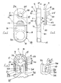
- Figure 1 is a front view of the cable stripping tool of this invention;
- Figure 2 is a side view of the tool of Figure 1 but with its cover plate separated from the main body and the elastic band partially cut away, for clarity;
- Figure 3 is a detailed part-view of the tool of Figures 1 and 2, showing the cutting blade in a first position;
- Figure 4 is a detailed view of the cutting blade, but in its second position; and
- Figures 5-1 to 5-VI show the five steps of the method of this invention, as employed to prepare the end portion of an electric co-axial cable and the finished cable.
- Referring initially to Figures 1 to 4, the cable stripping tool there shown has a
body 10, assembled from three moulded plastics material parts comprising amain body 11, acover plate 12 and ablade carrier 13. Themain body 11 andcover plate 12 fit together to define a slot within which a portion of theblade carrier 13 may slide, as will be apparent from the following description. - The
main body 11 has aside plate 14 from which a generallyU-shaped wall 15 upstands, leaving aflange 16 projecting beyond the U-shaped wall. In association with theside plate 14, the inner faces of thewall 15 define theslot 17 within which a generally rectangular portion of theblade carrier 13 may slide. The moulding of themain body 11 may includerecesses 18, to reduce the amount of plastics material employed and also to permit satisfactory production of the part by an injection moulding process, taking into account material shrinkage. - The
cover plate 12 is of substantially the same overall shape as theside plate 14, and has aflange 19 arranged in a similar manner to theflange 16 of themain body 11. Fivepins 20 project normally from the cover plate, which pins are received inbores 21 provided in the main body, to locate and hold the cover plate in the required position with respect to themain body 11.Pins 20 and bores 2.1 may appropriately be formed so that the main body and cover plate snap-fit together, or reliance may be placed simply on a frictional interfit between the pins and bores. Alternatively, the cover plate and main body may be glued together during the last stage of assembly of the tool. - A bore 22 is formed through the
side plate 14, which bore is of an appropriate diameter closely to receive the co-axial cable with which the tool is intended to be used. Theinside face 23 of the base of theU-shaped wall 15 extends substantially diametrically of thebore 22, and that wall is provided with asemicircular groove 24 contiguous with thebore 22, so as to permit a cable to be inserted through thebore 22 to the required extent. Thecover plate 12 similarly is formed with abore 25 co-axial with and of the same diameter as thebore 22, and on the outer face of the cover plate adjacent thebore 25 there is provided aguide piece 26, having twoguide surfaces - The
blade carrier 13 has afinger portion 29 including afinger hole 30 and amoulding recess 31 in which may be provided, for example, information concerning the particular sizing of the tool. Projecting from thefinger portion 29 is ablade portion 32, adapted for sliding movement within theslot 17 defined by themain body 11. Thetop face 33 of thisportion 32 is provided with asemi-circular groove 34, centrally positioned for alignment with thebore 22 in themain body 11. - The
blade portion 32 of theblade carrier 13 is provided with twopins cutting blade 37 pivotally mounted onpin 35. In addition to the hole adjacent the blade end remote from thecutting edge 38 closely fitting on thepin 35, the blade has aslot 39 in which is receivedpin 36. When so positioned, thecutting edge 38 of the blade is cordal with respect to thegroove 34. - The
blade 37 is of closely controlled dimensions and shape. The side edge ofslot 39 is tangential to the hole forpin 35 and thecutting edge 38 is accurately honed to lie at a predetermined acute angle to the major axis of theslot 39, a known distance from the hole which receives thepin 35. In addition, the relative positions of thepins groove 34 of thecarrier 13 are closely controlled. - It will thus be appreciated that with the blade pivoted to the position shown in Figure 3, with the
pin 36 engaging the right-hand edge of theslot 39, the amount by which thecutting edge 38 overlies thegroove 34 can be controlled by appropriate positioning of thepin 35. When the blade has pivoted so that the left hand side of theslot 39 engages the pin 36 (as shown in Figure 4) the amount by which thecutting edge 38 overlies thegroove 34 is increased, but limited by the spacing between thepins pins - As shown in Figure 2, the
pins U-shaped wall 15 of themain body 11 to be received in agroove 40 in thecover plate 12. When the tool is completely assembled, thisgroove 40 limits the movement of theblade carrier 13 away from themain body 11. - The tool is completed by means of a resilient
endless band 41 passed around theU-shaped wall 15, between theflanges finger portion 29 of theblade carrier 13. When so positioned, theband 41 should be in a state of tension, so that it holds theblade carrier 13 fully engaged in the slot in themain body 11. To facilitate relative separation of the blade carrier and themain body 11 to the extent limited bypin 35 ingroove 40, finger and thumbfriction grip portions side plate 14 andcover plate 12. - The above described tool is especially configured for use with a particular co-axial cable, to give a specified form of end portion preparation. When a cable of the correct type is to be prepared, the tool is "opened" by pulling the
blade carrier 13 away from themain body 11 against the resilient bias provided by theband 41, conveniently effected by inserting the middle finger throughfinger hole 30 and grasping the body between a thumb and forefinger, ongrips bore 22,past grooves bore 25 inplate 12, to project beyondface 28. The tool is then released to permit the band to draw theblade carrier 13 into the main body, whereafter the tool is rotated in a clockwise sense (as viewed in Figure 1 with the cable end-on). The drag of the blade on severing the layers of the cable causes the blade to move to the position illustrated in Figure 4 and so the blade effects a relatively deep cut, partially severing the insulating first layer overlying the core of the cable. - The tool is then opened again, and the cable pushed further through the bore until the cut already effected is aligned with
guide surface 27 of the guide piece. Then, the projecting portion of the cable is twisted, until little resistance is felt, so indicating that the end portion of the insulating first layer of the cable has been completely severed. This action also will twist together the strands of a multi-strand core conductor. The tool is then rotated clockwise again, so effecting a second cut partially severing the insulating first layer of the cable, the blade acting in precisely the same manner as has been described above. Preferably, the tool is at this point rotated sufficiently counterclockwise to move the blade to the position illustrated in Figure 3, to prevent the blade cutting right through the insulating third layer in the initial part of the next stage, described below. - In the next stage of the operation, the tool is opened again and the cable pushed yet further through the bore in the tool, until the second cut is aligned with the
second guide surface 28 of theguide piece 26. It is then rotated in a counterclockwise direction automatically to maintain the blade in the position illustrated in Figure 3, so performing a relatively shallow depth of cut, severing on the outer insulating third layer of the cable and leaving untouched the conducting second layer and the insulating first layer. To complete the preparation, the tool is gripped. across its ends, so urging therecesses - When using the tool of this invention, it will be appreciated that the blade need not immediately penetrate the cable to the required depth. The severing action may be gradual, as the tool is rotated, with the
band 41 gradually drawing the blade into the cable to the predetermined depth, as tool rotation is continued. Moreover, the operation of the tool is fully automatic in that the blade moves to either one of its two positions by virtue of the drag of the blade through the cable, depending on whether the tool is rotated clockwise or counter- clockwise. - Modification of the tool to suit different cables is relatively simple. Identical mouldings may be used, with the
bores grooves pins - The tool also may be modified to have the blade carrier removable from the body, by appropriate configuration of
pins plate 12 in the region ofslot 40. This will facilitate the changing of a blade, when blunted by repeated use. Spare blades may be carried in an appropriate recess, formed in the blade carrier for instance on the opposite face thereof to that from which pins 35 and 36 project. - In a further alternative, the
blade carrier 13 may include a slidable jaw opposed to and spring-urged towardsrecess 24 in the body. This jaw will engage the cable immediately on releasing the blade carrier, even though the blade may not have penetrated the cable so preventing therecess 34 engaging the cable. Such a jaw will serve to clamp the cable againstrecess 24, and also to hold the tool square, until the blade has sufficiently penetrated the cable on rotating the tool. - The method of using the tool described above will now be explained in greater detail, referring to Figures 5-1 to 5-VI. Shown in those Figures is a cable to be stripped, comprising a
copper conducting core 110, which may be a monofilament or multi-stranded, surrounded by afirst layer 111 of an appropriate dielectric material, having regard to the intended use for the cable. Thefirst layer 111 may comprise a solid sleeve for instance of polyethylene, or it may be of the air-cored variety. Closely overlying thefirst layer 111 is a conductingsecond layer 112, typically formed of a copper braid in the form of a sleeve. Again, having regard to the intended use of the cable, thesecond layer 112 may comprise two sub-layers, the first of which being a copper foil wound tightly around thefirst layer 111 and the second of which being a braided copper sleeve. The cable further comprises athird layer 113, in the form of an insulating sleeve made from an appropriate plastics material. This sleeve, in addition to providing an insulating layer, may also impart to the cable advantageous mechanical and physical properties such as strength, abrasion resistance, and so on. - Whilst the exact specification of the end portion preparation vary from connector to connector, in general it is necessary to expose a length of the conducting
core 110 at the end of the cable, then a length of the insulatingfirst layer 111, then a length of the conductingsecond layer 112. The end portion preparation thus requires the removal of a relatively long length of theouter layer 113, the removal of a lesser length of the conductingsecond layer 112 and the removal of a relatively short length of the insulatingfirst layer 111. - Step I of the method comprises making an annular cut 114 (for example with the tool of Figures 1 to 4, or with the tool of Figure 6, described below) in a radial plane fully around the cable to a first depth sufficient partially to sever the
first layer 111. The first cut may lie for example approximately 14 mm from the end of the cable and in the case of a typical electric co- axial cable, may penetrate thefirst layer 111 to a depth of approximately 50% of the radial thickness of that layer. - Step II of the method comprises rotating with a twisting motion, as shown by arrow A, the partially severed end portion of the cable, about the
core 110. This has the effect of separating thefirst layer 111 completely, as shown at 115. In addition, in the case of amulti-stranded core 110, this action also has the advantageous effect of twisting together the strands of thecore 110. - Step III is essentially the same as step I, in that an
annular cut 116 is made fully around the cable in a radial plane, at a position further from the end of the cable thancut 114 and typically 22 mm from the end of the cable. Cut 116 is made to precisely the same depth ascut 114, and so penetrates thefirst layer 111 to the same extent ascut 114. - In step IV, an
annular cut 117 is made fully around the cable in a radial plane further from the end of the cable thancuts third layer 113, to a depth of about 75% of the radial thickness of that layer. - In the final step V of the end portion preparation, a force B is applied axially of the cable and in the direction of the end thereof to the severed
third layer 113, the force being applied to that severed portion in the region of thethird cut 117. This force advantageously is applied by way of the knife blade used to form thecut 117, though any of a variety of tools could be used for this purpose - for example, a pair of pliers or side cutters. This force slides all the severed portions off the cable end portion, so leaving exposed a length ofcore 110, a length of insulatingfirst layer 111, and a length of conductingsecond layer 112, as shown in Figure 1-IV. - It will be appreciated that it is an important feature of this invention that the depth of the first, second and
third cuts
Claims (11)
Priority Applications (1)
| Application Number | Priority Date | Filing Date | Title |
|---|---|---|---|
| AT85300352T ATE35351T1 (en) | 1984-01-20 | 1985-01-18 | COAXIAL WIRE STRIPPING TOOL AND TERMINAL RESTORATION PROCESS. |
Applications Claiming Priority (4)
| Application Number | Priority Date | Filing Date | Title |
|---|---|---|---|
| GB8401513 | 1984-01-20 | ||
| GB848401513A GB8401513D0 (en) | 1984-01-20 | 1984-01-20 | Co-axial cable stripping tool |
| GB8413445 | 1984-05-25 | ||
| GB848413445A GB8413445D0 (en) | 1984-01-20 | 1984-05-25 | Co-axial cable stripping tool |
Publications (3)
| Publication Number | Publication Date |
|---|---|
| EP0150113A2 EP0150113A2 (en) | 1985-07-31 |
| EP0150113A3 EP0150113A3 (en) | 1985-08-14 |
| EP0150113B1 true EP0150113B1 (en) | 1988-06-22 |
Family
ID=26287207
Family Applications (1)
| Application Number | Title | Priority Date | Filing Date |
|---|---|---|---|
| EP85300352A Expired EP0150113B1 (en) | 1984-01-20 | 1985-01-18 | Co-axial cable stripping tool and end portion preparation method |
Country Status (12)
| Country | Link |
|---|---|
| US (1) | US4640009A (en) |
| EP (1) | EP0150113B1 (en) |
| AU (1) | AU3839385A (en) |
| BR (1) | BR8504780A (en) |
| DE (1) | DE3563500D1 (en) |
| DK (1) | DK411385A (en) |
| ES (2) | ES8605656A1 (en) |
| FI (1) | FI853390L (en) |
| GB (2) | GB2153157B (en) |
| IN (1) | IN162354B (en) |
| NO (1) | NO853678L (en) |
| WO (1) | WO1985003389A1 (en) |
Families Citing this family (21)
| Publication number | Priority date | Publication date | Assignee | Title |
|---|---|---|---|---|
| US4805302A (en) * | 1987-11-17 | 1989-02-21 | Rostra Tool Company | Wire stripper |
| GB2215143B (en) * | 1988-02-05 | 1991-11-06 | Barry Peter Liversidge | Wire stripper |
| US4934219A (en) * | 1988-11-04 | 1990-06-19 | Edwards Daniel B | Coaxial cable stripper tool and method |
| GB2226269B (en) * | 1988-12-22 | 1992-11-25 | Zdzislaw Bieganski | Cable stripper |
| US5074043A (en) * | 1990-11-26 | 1991-12-24 | Mills Edward O | Safety-cable jacket remover |
| CA2106466A1 (en) * | 1991-03-22 | 1992-09-23 | Corey J. Mcmills | Coaxial cable connector with mandrel spacer and method of preparing coaxial cable |
| DE4321546C1 (en) * | 1993-06-29 | 1994-12-22 | Franz Rothleitner | Method and device for automatic stripping of a multicore cable which is provided with an insulating sheath and a screen |
| US5457877A (en) * | 1994-06-27 | 1995-10-17 | At&T Corp. | Apparatus and method for cutting through cable sheathings |
| US5577150A (en) * | 1995-10-11 | 1996-11-19 | Alcatel Na Cable Systems, Inc. | Method and tool for accessing optical fibers within a buffer tube |
| US6134363A (en) * | 1999-02-18 | 2000-10-17 | Alcatel | Method for accessing optical fibers in the midspan region of an optical fiber cable |
| SE522838C2 (en) | 2001-12-19 | 2004-03-09 | Pressmaster Ab | Cable scaling device |
| US20030188432A1 (en) * | 2002-04-06 | 2003-10-09 | Temple Larry Dan | Cable and wire stripper |
| US6813981B2 (en) * | 2002-11-30 | 2004-11-09 | Bellsouth Intellectual Property Corporation | Apparatus and method for cutting cables and wires |
| US20040159197A1 (en) * | 2003-02-13 | 2004-08-19 | Kevin Forsberg | Apparatus and method for cutting cables and wires |
| US7137204B2 (en) * | 2004-09-22 | 2006-11-21 | Wiste Rodney J | Wire tool system and method |
| WO2008022143A1 (en) * | 2006-08-14 | 2008-02-21 | Fischer Brett W | Cartridge tip cutting device and method |
| DE102013003384B4 (en) * | 2013-03-01 | 2015-09-03 | Phoenix Contact Gmbh & Co. Kg | Method and device for assembling a multi-core round cable |
| US9225152B2 (en) * | 2014-03-31 | 2015-12-29 | Wayne Anderson | Multi-function wire stripping hand tool and kit and method for using same |
| US9425593B2 (en) | 2014-11-18 | 2016-08-23 | Hanlong Industrial Co., Ltd. | Stripping tool |
| CA3019328A1 (en) | 2016-03-27 | 2017-10-05 | Southwire Company, Llc | Cable stripper |
| US11527874B1 (en) | 2022-06-28 | 2022-12-13 | Araspeed Tool Company LLC | Wire tool for stripping and terminating electrical wires and methods of using the same |
Family Cites Families (7)
| Publication number | Priority date | Publication date | Assignee | Title |
|---|---|---|---|---|
| US3204495A (en) * | 1964-02-06 | 1965-09-07 | James J Matthews | Insulation removing tool |
| GB1164544A (en) * | 1967-05-10 | 1969-09-17 | British Insulated Callenders | An improved Hand Tool for Cutting Cable Sheaths |
| US3486216A (en) * | 1967-10-17 | 1969-12-30 | Gerald N Cimolino | Co-axial cable stripping,trimming and cutting tool |
| GB1238342A (en) * | 1968-03-27 | 1971-07-07 | ||
| NL188438C (en) * | 1976-06-09 | 1992-06-16 | Pressmaster Tool Ab | DEVICE FOR REMOVING THE COATING OF AN ESPECIALLY ROD-SHAPED OBJECT. |
| US4366619A (en) * | 1980-12-29 | 1983-01-04 | Zdzislaw Bieganski | Cable stripper |
| DE3263749D1 (en) * | 1981-08-28 | 1985-06-27 | Weidmueller C A Gmbh Co | Wire stripping tool |
-
1985
- 1985-01-18 GB GB08501338A patent/GB2153157B/en not_active Expired
- 1985-01-18 BR BR8504780A patent/BR8504780A/en unknown
- 1985-01-18 GB GB08501339A patent/GB2153158B/en not_active Expired
- 1985-01-18 US US06/770,870 patent/US4640009A/en not_active Expired - Lifetime
- 1985-01-18 IN IN34/DEL/85A patent/IN162354B/en unknown
- 1985-01-18 WO PCT/GB1985/000024 patent/WO1985003389A1/en active Application Filing
- 1985-01-18 AU AU38393/85A patent/AU3839385A/en not_active Abandoned
- 1985-01-18 ES ES539685A patent/ES8605656A1/en not_active Expired
- 1985-01-18 DE DE8585300352T patent/DE3563500D1/en not_active Expired
- 1985-01-18 EP EP85300352A patent/EP0150113B1/en not_active Expired
- 1985-09-04 FI FI853390A patent/FI853390L/en not_active Application Discontinuation
- 1985-09-10 DK DK411385A patent/DK411385A/en not_active Application Discontinuation
- 1985-09-19 NO NO853678A patent/NO853678L/en unknown
- 1985-11-29 ES ES1985290610U patent/ES290610Y/en not_active Expired
Also Published As
| Publication number | Publication date |
|---|---|
| GB2153157B (en) | 1988-11-02 |
| GB2153157A (en) | 1985-08-14 |
| BR8504780A (en) | 1985-12-24 |
| ES290610U (en) | 1986-04-01 |
| ES290610Y (en) | 1986-11-16 |
| IN162354B (en) | 1988-05-14 |
| DK411385D0 (en) | 1985-09-10 |
| WO1985003389A1 (en) | 1985-08-01 |
| GB8501339D0 (en) | 1985-02-20 |
| DK411385A (en) | 1985-09-10 |
| ES539685A0 (en) | 1986-04-01 |
| GB2153158B (en) | 1987-06-24 |
| GB2153158A (en) | 1985-08-14 |
| FI853390A0 (en) | 1985-09-04 |
| US4640009A (en) | 1987-02-03 |
| ES8605656A1 (en) | 1986-04-01 |
| FI853390L (en) | 1985-09-04 |
| AU3839385A (en) | 1985-08-09 |
| EP0150113A3 (en) | 1985-08-14 |
| NO853678L (en) | 1985-09-19 |
| DE3563500D1 (en) | 1988-07-28 |
| EP0150113A2 (en) | 1985-07-31 |
| GB8501338D0 (en) | 1985-02-20 |
Similar Documents
| Publication | Publication Date | Title |
|---|---|---|
| EP0150113B1 (en) | Co-axial cable stripping tool and end portion preparation method | |
| US6467171B2 (en) | Compound coaxial cable stripping tool | |
| EP0871270B1 (en) | Hand tool | |
| US5062192A (en) | Cable stripping tool | |
| JP2980568B2 (en) | Cable stripper | |
| US5009006A (en) | Cable stripping tool | |
| JPS61140906A (en) | Sheath peeler for cable | |
| JPS6133329B2 (en) | ||
| US4953428A (en) | Tool for stripping cables, in particular constituted cables | |
| US20230051525A1 (en) | Cable Stripping Tool | |
| JP2000056139A (en) | Method for peeling external jacket from optical fiber cable and optical fiber jacket peeling tool | |
| US4766669A (en) | Stripping method and apparatus for coaxial cable | |
| US3361015A (en) | End stripping tool | |
| GB2182503A (en) | Co-axial cable stripping tool | |
| EP0652617A1 (en) | Electric cable for connector and its production method and apparatus | |
| JPH0532967B2 (en) | ||
| GB2215143A (en) | Wire stripper | |
| US4985996A (en) | Wire stripper with V-notch blade | |
| GB2284945A (en) | Tools for cutting and stripping cables | |
| CN111613948B (en) | Method for manufacturing electric wire with waterproof plug | |
| US5311663A (en) | Device for trimming coaxial cable | |
| JPH079549Y2 (en) | Stripper for flat shielded cable | |
| GB2052887A (en) | Apparatus for preparing the ends of coaxial cables | |
| JPH10268139A (en) | Removal tool for optical fiber conductor cover and cover removal method | |
| JP2003052110A (en) | Intermediate peeler for peeling housing linear body |
Legal Events
| Date | Code | Title | Description |
|---|---|---|---|
| PUAI | Public reference made under article 153(3) epc to a published international application that has entered the european phase |
Free format text: ORIGINAL CODE: 0009012 |
|
| PUAL | Search report despatched |
Free format text: ORIGINAL CODE: 0009013 |
|
| AK | Designated contracting states |
Designated state(s): AT BE CH DE FR IT LI LU NL SE |
|
| AK | Designated contracting states |
Designated state(s): AT BE CH DE FR IT LI LU NL SE |
|
| 17P | Request for examination filed |
Effective date: 19860205 |
|
| 17Q | First examination report despatched |
Effective date: 19861022 |
|
| GRAA | (expected) grant |
Free format text: ORIGINAL CODE: 0009210 |
|
| AK | Designated contracting states |
Kind code of ref document: B1 Designated state(s): AT BE CH DE FR IT LI LU NL SE |
|
| PG25 | Lapsed in a contracting state [announced via postgrant information from national office to epo] |
Ref country code: NL Effective date: 19880622 Ref country code: LI Effective date: 19880622 Ref country code: IT Free format text: LAPSE BECAUSE OF FAILURE TO SUBMIT A TRANSLATION OF THE DESCRIPTION OR TO PAY THE FEE WITHIN THE PRESCRIBED TIME-LIMIT;WARNING: LAPSES OF ITALIAN PATENTS WITH EFFECTIVE DATE BEFORE 2007 MAY HAVE OCCURRED AT ANY TIME BEFORE 2007. THE CORRECT EFFECTIVE DATE MAY BE DIFFERENT FROM THE ONE RECORDED. Effective date: 19880622 Ref country code: FR Free format text: THE PATENT HAS BEEN ANNULLED BY A DECISION OF A NATIONAL AUTHORITY Effective date: 19880622 Ref country code: CH Effective date: 19880622 Ref country code: BE Effective date: 19880622 Ref country code: AT Effective date: 19880622 |
|
| REF | Corresponds to: |
Ref document number: 35351 Country of ref document: AT Date of ref document: 19880715 Kind code of ref document: T |
|
| PG25 | Lapsed in a contracting state [announced via postgrant information from national office to epo] |
Ref country code: SE Effective date: 19880630 |
|
| REF | Corresponds to: |
Ref document number: 3563500 Country of ref document: DE Date of ref document: 19880728 |
|
| REG | Reference to a national code |
Ref country code: CH Ref legal event code: PL |
|
| NLV1 | Nl: lapsed or annulled due to failure to fulfill the requirements of art. 29p and 29m of the patents act | ||
| EN | Fr: translation not filed | ||
| PG25 | Lapsed in a contracting state [announced via postgrant information from national office to epo] |
Ref country code: LU Free format text: LAPSE BECAUSE OF NON-PAYMENT OF DUE FEES Effective date: 19890131 |
|
| PLBE | No opposition filed within time limit |
Free format text: ORIGINAL CODE: 0009261 |
|
| STAA | Information on the status of an ep patent application or granted ep patent |
Free format text: STATUS: NO OPPOSITION FILED WITHIN TIME LIMIT |
|
| 26N | No opposition filed | ||
| PG25 | Lapsed in a contracting state [announced via postgrant information from national office to epo] |
Ref country code: DE Effective date: 19891003 |