EP0149772A2 - Pulp thickening utilizing stationary screens - Google Patents
Pulp thickening utilizing stationary screens Download PDFInfo
- Publication number
- EP0149772A2 EP0149772A2 EP84114804A EP84114804A EP0149772A2 EP 0149772 A2 EP0149772 A2 EP 0149772A2 EP 84114804 A EP84114804 A EP 84114804A EP 84114804 A EP84114804 A EP 84114804A EP 0149772 A2 EP0149772 A2 EP 0149772A2
- Authority
- EP
- European Patent Office
- Prior art keywords
- extraction
- arms
- vessel
- filtrate
- screens
- Prior art date
- Legal status (The legal status is an assumption and is not a legal conclusion. Google has not performed a legal analysis and makes no representation as to the accuracy of the status listed.)
- Granted
Links
Images

Classifications
-
- D—TEXTILES; PAPER
- D21—PAPER-MAKING; PRODUCTION OF CELLULOSE
- D21C—PRODUCTION OF CELLULOSE BY REMOVING NON-CELLULOSE SUBSTANCES FROM CELLULOSE-CONTAINING MATERIALS; REGENERATION OF PULPING LIQUORS; APPARATUS THEREFOR
- D21C9/00—After-treatment of cellulose pulp, e.g. of wood pulp, or cotton linters ; Treatment of dilute or dewatered pulp or process improvement taking place after obtaining the raw cellulosic material and not provided for elsewhere
- D21C9/02—Washing ; Displacing cooking or pulp-treating liquors contained in the pulp by fluids, e.g. wash water or other pulp-treating agents
-
- B—PERFORMING OPERATIONS; TRANSPORTING
- B01—PHYSICAL OR CHEMICAL PROCESSES OR APPARATUS IN GENERAL
- B01D—SEPARATION
- B01D33/00—Filters with filtering elements which move during the filtering operation
- B01D33/06—Filters with filtering elements which move during the filtering operation with rotary cylindrical filtering surfaces, e.g. hollow drums
- B01D33/11—Filters with filtering elements which move during the filtering operation with rotary cylindrical filtering surfaces, e.g. hollow drums arranged for outward flow filtration
-
- B—PERFORMING OPERATIONS; TRANSPORTING
- B01—PHYSICAL OR CHEMICAL PROCESSES OR APPARATUS IN GENERAL
- B01D—SEPARATION
- B01D36/00—Filter circuits or combinations of filters with other separating devices
- B01D36/02—Combinations of filters of different kinds
Definitions
- the invention relates to a method and apparatus primarily adapted for treating a comminuted cellulosic fibrous material suspension, such as pulp for the production of paper.
- the invention primarily relates to the thickening of the suspension from a relatively low consistency (e.g., about 1-1/2%), to a higher, more desirable consistency (e.g., between about 9-14%).
- the invention is particularly adapted for use with the general apparatus illustrated and described applicant's application No.
- the basic apparatus disclosed in the above mentioned application includes an upright cylindrical vessel having a vertical axis, a plurality of annular, stationary screens disposed within the vessel and spaced from each other and from the axis; a plurality of radially extending extraction arms physically and hydraulically connected to the stationary annular screens, the extraction arms partitioning the vessel into a plurality of radial segments of substantially the same cross-sectional area, and the screens partitioning each radial segment into a plurality of vertically extending channels; and a suspension inlet means mounted below the extraction arms and the screens.
- Such a structure also includes a central shaft mounted for rotation within the vessel about its axis, and provides that each screen segment of each of the screen structures in a particular radial segment is hydraulically connected to the same extraction arm, and only a single extraction arm.
- a plurality of extraction conduits, one extending from each of the extraction arms, are provided, as well as extraction valve means for controlling the flow of liquid from each of the extraction arms.
- a method and apparatus are provided for thickening of the suspension, preferably between its introduction into the inlet means of the vessel described above, and prior to moving into operative relationship with the stationary annular screens of the vessel described above.
- the thickening means comprises a plurality of rotatable hollow arms, rotatable about said axis, the arms mounting a plurality of annular screens thereon, which screens are hydraulically connected to the hollow arms.
- each screen segment of each of the screen structures in a particular radial segment defined by the hollow radially extending arm is hydraulically connected to the same hollow arm, and only a single hollow arm.
- a plurality of filtrate conduits one extending from each of the hollow arms, are provided, as well as filtrate valve means for controlling the flow of filtrate from each of the hollow arms.
- the number of rotatable hollow arms is half the number of extraction arms, and the hollow arms are rotated by a second, hollow, shaft in a direction - preferably but not necessarily - opposite to the direction of rotation of the central shaft, and at a higher speed.
- the thickening of suspension from a low consistency (e.g., about 1-1/2%) to a higher consistency (e.g., between about 9-14%) is practiced by rotating the second shaft connected to the hollow rotatable arms - with annular screens connected thereto - in the opposite direction as the central shaft.
- the central shaft is attached to a mechanism for extracting a portion of the entire radial extent of the suspension at the cross-sectional area of the top of the suspension column in the vessel, and at that part of the top of the column preceding the radial segment to which the suspension is being introduced after being thickened at the bottom of the column.
- the present invention also relates to the thickening apparatus, per se, for accomplishing suspension thickening.
- the method and apparatus according to the present invention are preferably utilizable in conjunction with the method and apparatus described in Applicant's aforementioned application.
- the apparatus illustrated in that application includes a cylindrical generally upright vessel 11, having a bottom portion 12 into which the suspension to be treated is passed, and a top portion 13 from which treatment suspension is withdrawn.
- a suspension inlet structure 14 introduces the suspension to be treated into the vessel 11.
- a plurality of annular, stationary screens 16, concentric with the axis A-A of the vessel 11, are provided.
- the screens 16 are disposed within the vessel 11 and spaced from each other and from the axis A, and are physically and hydraulically connected to a plurality of radially extending extraction arms 20 (e.g., 12 extraction arms).
- the extraction arms 20 partition the vessel into a plurality of radial segments of substantially the same cross-sectional area, and the screens 16 partition each radial segment into a plurality of vertically extending channels.
- the apparatus disclosed in Applicant's aforementioned application also preferably includes a central rotating shaft 15 disposed along the vertical axis A-A of the vessel 11, to which a plurality of treatment-fluid introducing structures (not shown) may be attached, and to which a treated-suspension removal structure (not shown) is attached.
- the removal structure continuously removes from the top portion of the vessel 11 above the level of the screens 16 a portion of the entire radial extent of the suspension thereat.
- Extraction valve means 22 are provided for controlling the extraction of liquid from the arms 20.
- a suspension thickening means shown generally by reference numeral 24 in FIGURE 1, is provided mounted in the vessel 11 below the screens 16 and extraction arms 20, and above the suspension inlet 14.
- the rotating bottom pulp distributor column illustrated and described in said copending application is replaced by the thickening means 24, however the thickening means provides the same desired controlled introduction of pulp into operative association with the screens 16.
- the pulp thickening means 24 comprises a plurality of hollow, radially extending, rotatable arms 25. These arms 25 partition the vessel 11 into a plurality of radial segments just like the extraction arms 20, only normally one-half the number of arms 25 would be provided as the number of arms 20 (e.g., six instead of twelve). Mounted to the arms 25 for rotation therewith are a plurality of annular screens 26, which partition each radial segment defined by the arms 25 into a plurality of vertically extending channels.
- a second shaft 27 effects rotation of the arms 25, being received by bearings 28 at the bottom of vessel 11 for rotation with respect to the vessel 11, and being driven by a drive mechanism 29 distinct from - although in sync with (as will be hereinafter described) - the drive mechanism 30 for the central shaft 15.
- the second shaft 27 preferably is hollow, and concentric with the central shaft 15, as illustrated in the drawings, and a plurality of filtrate conduits 31 extend therethrough.
- Each conduit 31 is physically and hydraulically connected at the top end thereof to an extractions arms 25, and rotates with the shaft 27 and the extraction arm 25.
- each filtrate conduit 31 is connected to a filtrate outlet manifold 32, which in turn is connected to filtrate outlet pipe 33.
- Spider arms 34 within the vessel 11 between the suspension inlet 14 and the arms 25, also provide a bearing means for 35 for the second shaft 27.
- the bottoms of the filtrate conduits 31 are connected to a common annular support 36 (see FIGURES 1 and 3 through 5) and disposed in a circle.
- Support 36 is affixed to the interior of the second shaft 27.
- a filtrate valve means 38 At the bottom of the support 36 is provided a filtrate valve means 38 (see FIGURES 1, 4 and 5) which is connected to the central shaft 15 for rotation therewith.
- the valve means 38 preferably comprises an arcuate rotatable valve member 39 having a radial extent of approximately the same as the arcuate spacing between a pair of adjacent conduits 31, and - as illustrated in FIGURE 5 - preferably includes a wear member 40, of substantially the same arcuate extent as member 39, that is spring-pressed by one or more springs 41 into tight engagement the support 36 so that when member 40 covers a conduit 31 substantially no flow of filtrate through the conduit 31 into the header 32 takes place.
- the rotatable annular screens 26 are preferably connected to the arms 25 in the same way that the screens 16 are connected to the extraction arms 20 - that is, each screen segment of each annular screen 26 of a particular radial segment is hydraulically connected to the same hollow arm 25, and only a single arm 25.
- the filtrate valve means 38 controls the flow of filtrate from each of the arms 25.
- the valve means 38 is readily accessible by unbolting plate 43 from flange 44 connected to shaft 27 (see FIGURE I) and unbolting plate 45 of shaft segment 46 connected to drive 29, allowing free access to the interior of the second shaft 27 from the bottom thereof.
- the thickening means 24 preferably is rotated by shaft 27 and drive 29 in the opposite direction as the rotation of the shaft 15 (with associated treated-suspension removal structure) so that thickening shut-off is always moving into the up-flow zone.
- the rotation of the thickening means 24 also is preferably faster than the rotation of the shaft 15, for instance, the shaft 27 is rotated by drive 29 at 5-7 rpm while the shaft 15 is rotated by drive 30 at 2-3 rpm.
- the faster rotation of the thickening means provides a wiping action on the screens 26, and mixing action for the pulp within the thickening zone (i.e., adjacent the screens 26) so as to provide a uniform consistency of pulp moving upwardly past the screens 26.
- the pulp consistency must be uniform when it reaches the extraction arms 20.
- the synchronization can be accomplished in any desirable manner, for instance, by providing any suitable synchronizing control means 49 operatively connected to the drives 29 and 30, when the drive 30 and shaft 15 are operatively connected to the extraction valve means 22 (as illustrated in FIGURE 1).
- any suitable synchronizing control means 49 operatively connected to the drives 29 and 30, when the drive 30 and shaft 15 are operatively connected to the extraction valve means 22 (as illustrated in FIGURE 1).
- other synchronizing means may also be provided, as described in said earlier application.
- filtrate extraction mechanisms could also be utilized, aside from the particular extraction conduits 31 and associated valve means 38.
- extraction could be provided by headers and valve means in operative association with the outer ends of the arms 25 as they are rotated in their paths, and such valve means could be synchronized with the extraction valve means illustrated in FIGURE 8 of Applicant's earlier application.
- pulp at low consistency (e.g., from about 1-1/2%),is fed through inlet 14 to flow upwardly in vessel 11.
- pulp at low consistency e.g., from about 1-1/2%
- the pulp is thickened by filtrate being withdrawn therefrom, passing through screens 26 and arms 25, through conduits 31, header 32, and out through filtrate outlet 33. See the left-hand side of FIGURE 1 at screens 26.
- the filtrate valve means 38 has cut-off the extraction flow through one of the arms 25, and the pulp flows upwardly in that area to the diffuser portion of the vessel, defined by the stationary screens 16.
- Extraction into the upflow area through arms 20 is cut-off by the extraction valve means 22 for the particular radial segment of the vessel 11 where upflow is taking place, while there is continuous removal from a top portion of the vessel 11, above the level of the screens 16, a portion of the entire radial extent of the suspension at the top of the column preceding the radial segment into which the suspension is being introduced (flowing upwardly past the screens 26).
- the relatively high speed of rotation (e.g., 5-7 rpm) of the screens 26 effects a wiping action, and imparts a turbulent, mixing, action to the pulp so as to provide uniform consistency when the pulp leaves the thickening means 24.
- the pulp upflows from thickening means 24 into a particular upper radial segment of the vessel 11 it has a uniform consistency, preferably between about 9-14%, which is the optimum consistency for treatment in the diffuser section of the vessel 11.
Landscapes
- Chemical & Material Sciences (AREA)
- Chemical Kinetics & Catalysis (AREA)
- Life Sciences & Earth Sciences (AREA)
- Engineering & Computer Science (AREA)
- Wood Science & Technology (AREA)
- Paper (AREA)
- Diaphragms For Electromechanical Transducers (AREA)
- Ceramic Products (AREA)
- Compression Or Coding Systems Of Tv Signals (AREA)
- Mechanical Treatment Of Semiconductor (AREA)
- Filtration Of Liquid (AREA)
Abstract
Description
- The invention relates to a method and apparatus primarily adapted for treating a comminuted cellulosic fibrous material suspension, such as pulp for the production of paper. The invention primarily relates to the thickening of the suspension from a relatively low consistency (e.g., about 1-1/2%), to a higher, more desirable consistency (e.g., between about 9-14%).
- The invention is particularly adapted for use with the general apparatus illustrated and described applicant's application No.
- filed . In that application, a simple and effective method and apparatus are provided for the treatment of a suspension, such as pulp suitable for use in making paper, utilizing stationary screens. The utilization of stationary screens as described in said application greatly simplifies the suspension treating procedure, yet no significant screen clogging - which would result in non-uniform treatment - occurs.
- The basic apparatus disclosed in the above mentioned application includes an upright cylindrical vessel having a vertical axis, a plurality of annular, stationary screens disposed within the vessel and spaced from each other and from the axis; a plurality of radially extending extraction arms physically and hydraulically connected to the stationary annular screens, the extraction arms partitioning the vessel into a plurality of radial segments of substantially the same cross-sectional area, and the screens partitioning each radial segment into a plurality of vertically extending channels; and a suspension inlet means mounted below the extraction arms and the screens. Such a structure also includes a central shaft mounted for rotation within the vessel about its axis, and provides that each screen segment of each of the screen structures in a particular radial segment is hydraulically connected to the same extraction arm, and only a single extraction arm. A plurality of extraction conduits, one extending from each of the extraction arms, are provided, as well as extraction valve means for controlling the flow of liquid from each of the extraction arms.
- According to the present invention, a method and apparatus are provided for thickening of the suspension, preferably between its introduction into the inlet means of the vessel described above, and prior to moving into operative relationship with the stationary annular screens of the vessel described above. The thickening means comprises a plurality of rotatable hollow arms, rotatable about said axis, the arms mounting a plurality of annular screens thereon, which screens are hydraulically connected to the hollow arms. As with the extraction arms and stationary screens, each screen segment of each of the screen structures in a particular radial segment defined by the hollow radially extending arm is hydraulically connected to the same hollow arm, and only a single hollow arm. A plurality of filtrate conduits, one extending from each of the hollow arms, are provided, as well as filtrate valve means for controlling the flow of filtrate from each of the hollow arms. Preferably, the number of rotatable hollow arms is half the number of extraction arms, and the hollow arms are rotated by a second, hollow, shaft in a direction - preferably but not necessarily - opposite to the direction of rotation of the central shaft, and at a higher speed.
- In the practice of the general method according to the present invention, the thickening of suspension from a low consistency (e.g., about 1-1/2%) to a higher consistency (e.g., between about 9-14%) is practiced by rotating the second shaft connected to the hollow rotatable arms - with annular screens connected thereto - in the opposite direction as the central shaft. The central shaft is attached to a mechanism for extracting a portion of the entire radial extent of the suspension at the cross-sectional area of the top of the suspension column in the vessel, and at that part of the top of the column preceding the radial segment to which the suspension is being introduced after being thickened at the bottom of the column.
- The present invention also relates to the thickening apparatus, per se, for accomplishing suspension thickening.
- It is the primary object of the present invention to provide a simple and effective mechanism for the thickening of a suspension, such as pulp, primarily in a system utilizing stationary screens for the subsequent treatment of the suspension. This and other objects of the present invention will become clear from an inspection of the detailed description of the invention, and from the appended claims.
-
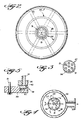
- FIGURE 1 is a side view, partly in cross-section and partly in elevation, of an exemplary diffusion apparatus utilizing an exemplary pulp thickening apparatus according to the present invention;
- FIGURE 2 is a cross-sectional view taken along lines 2-2 of FIGURE 1;
- FIGURE 3 is a cross-sectional view taken along lines 3-3 of FIGURE 1;
- FIGURE 4 is a cross-sectional view taken along lines 4-4 of FIGURE 1; and
- FIGURE 5 is a detailed view, partly in cross-section and partly in elevation, of a particular filtrate valve means in the structure of FIGURE 1.
- The method and apparatus according to the present invention are preferably utilizable in conjunction with the method and apparatus described in Applicant's aforementioned application. The apparatus illustrated in that application includes a cylindrical generally upright vessel 11, having a
bottom portion 12 into which the suspension to be treated is passed, and atop portion 13 from which treatment suspension is withdrawn. Asuspension inlet structure 14 introduces the suspension to be treated into the vessel 11. A plurality of annular,stationary screens 16, concentric with the axis A-A of the vessel 11, are provided. Thescreens 16 are disposed within the vessel 11 and spaced from each other and from the axis A, and are physically and hydraulically connected to a plurality of radially extending extraction arms 20 (e.g., 12 extraction arms). Theextraction arms 20 partition the vessel into a plurality of radial segments of substantially the same cross-sectional area, and thescreens 16 partition each radial segment into a plurality of vertically extending channels. - The apparatus disclosed in Applicant's aforementioned application also preferably includes a central rotating
shaft 15 disposed along the vertical axis A-A of the vessel 11, to which a plurality of treatment-fluid introducing structures (not shown) may be attached, and to which a treated-suspension removal structure (not shown) is attached. The removal structure continuously removes from the top portion of the vessel 11 above the level of the screens 16 a portion of the entire radial extent of the suspension thereat. Extraction valve means 22 are provided for controlling the extraction of liquid from thearms 20. - According to the apparatus of the present invention, a suspension thickening means, shown generally by
reference numeral 24 in FIGURE 1, is provided mounted in the vessel 11 below thescreens 16 andextraction arms 20, and above thesuspension inlet 14. The rotating bottom pulp distributor column illustrated and described in said copending application is replaced by thethickening means 24, however the thickening means provides the same desired controlled introduction of pulp into operative association with thescreens 16. - The pulp thickening means 24 comprises a plurality of hollow, radially extending,
rotatable arms 25. Thesearms 25 partition the vessel 11 into a plurality of radial segments just like theextraction arms 20, only normally one-half the number ofarms 25 would be provided as the number of arms 20 (e.g., six instead of twelve). Mounted to thearms 25 for rotation therewith are a plurality ofannular screens 26, which partition each radial segment defined by thearms 25 into a plurality of vertically extending channels. - A
second shaft 27 effects rotation of thearms 25, being received bybearings 28 at the bottom of vessel 11 for rotation with respect to the vessel 11, and being driven by adrive mechanism 29 distinct from - although in sync with (as will be hereinafter described) - thedrive mechanism 30 for thecentral shaft 15. Thesecond shaft 27 preferably is hollow, and concentric with thecentral shaft 15, as illustrated in the drawings, and a plurality offiltrate conduits 31 extend therethrough. Eachconduit 31 is physically and hydraulically connected at the top end thereof to anextractions arms 25, and rotates with theshaft 27 and theextraction arm 25. At the bottom end, eachfiltrate conduit 31 is connected to afiltrate outlet manifold 32, which in turn is connected tofiltrate outlet pipe 33.Spider arms 34 within the vessel 11 between thesuspension inlet 14 and thearms 25, also provide a bearing means for 35 for thesecond shaft 27. - The bottoms of the
filtrate conduits 31 are connected to a common annular support 36 (see FIGURES 1 and 3 through 5) and disposed in a circle.Support 36 is affixed to the interior of thesecond shaft 27. At the bottom of thesupport 36 is provided a filtrate valve means 38 (see FIGURES 1, 4 and 5) which is connected to thecentral shaft 15 for rotation therewith. As illustrated in FIGURE 4, the valve means 38 preferably comprises an arcuaterotatable valve member 39 having a radial extent of approximately the same as the arcuate spacing between a pair ofadjacent conduits 31, and - as illustrated in FIGURE 5 - preferably includes awear member 40, of substantially the same arcuate extent asmember 39, that is spring-pressed by one ormore springs 41 into tight engagement thesupport 36 so that whenmember 40 covers aconduit 31 substantially no flow of filtrate through theconduit 31 into theheader 32 takes place. - The rotatable
annular screens 26 are preferably connected to thearms 25 in the same way that thescreens 16 are connected to the extraction arms 20 - that is, each screen segment of eachannular screen 26 of a particular radial segment is hydraulically connected to the samehollow arm 25, and only asingle arm 25. The filtrate valve means 38 controls the flow of filtrate from each of thearms 25. The valve means 38 is readily accessible byunbolting plate 43 fromflange 44 connected to shaft 27 (see FIGURE I) andunbolting plate 45 ofshaft segment 46 connected to drive 29, allowing free access to the interior of thesecond shaft 27 from the bottom thereof. - In the utilization of the
thickener 24, the same principles apply as in said earlier application. That is in sequence the extraction through a givenarm 25 is cut off at the same time extraction in the arm orarm 20 thereabove is cut off. Thus, the channelling and pulp movement in the desired area of the vessel 11 are controlled. The thickening means 24 preferably is rotated byshaft 27 and drive 29 in the opposite direction as the rotation of the shaft 15 (with associated treated-suspension removal structure) so that thickening shut-off is always moving into the up-flow zone. The rotation of the thickening means 24 also is preferably faster than the rotation of theshaft 15, for instance, theshaft 27 is rotated bydrive 29 at 5-7 rpm while theshaft 15 is rotated by drive 30 at 2-3 rpm. The faster rotation of the thickening means provides a wiping action on thescreens 26, and mixing action for the pulp within the thickening zone (i.e., adjacent the screens 26) so as to provide a uniform consistency of pulp moving upwardly past thescreens 26. The pulp consistency must be uniform when it reaches theextraction arms 20. - As can be seen from an inspection of FIGURE 1, when filtrate extraction through a
conduit 31 is shut-off by the filtrate valve means 38 for any givenarm 25, the thickened pulp will flow upwardly in the radial segment of thescreen portions 26 connected to that givenarm 25. The filtrate valve means 38 is synchronized with the extraction valve means 22 so that when the pulp is flowing upwardlypast screens 26 to the upper part of the vessel 11, extraction through thearm 20 at the coincident upper part of the vessel 11 is also cut-off, so as to provide a maximum upflow pressure at that point. The synchronization can be accomplished in any desirable manner, for instance, by providing any suitable synchronizing control means 49 operatively connected to thedrives drive 30 andshaft 15 are operatively connected to the extraction valve means 22 (as illustrated in FIGURE 1). Of course, other synchronizing means may also be provided, as described in said earlier application. - Other filtrate extraction mechanisms could also be utilized, aside from the
particular extraction conduits 31 and associated valve means 38. For instance, extraction could be provided by headers and valve means in operative association with the outer ends of thearms 25 as they are rotated in their paths, and such valve means could be synchronized with the extraction valve means illustrated in FIGURE 8 of Applicant's earlier application. - According to an exemplary method of the present invention, pulp at low consistency (e.g., from about 1-1/2%),is fed through
inlet 14 to flow upwardly in vessel 11. At approximately five-sixth's of the area within the bottom of the vessel 11, at the thickening screens 26, the pulp is thickened by filtrate being withdrawn therefrom, passing throughscreens 26 andarms 25, throughconduits 31,header 32, and out throughfiltrate outlet 33. See the left-hand side of FIGURE 1 atscreens 26. At the other one-sixth of the area - see the right-hand side of FIGURE 1 at screens 26 - the filtrate valve means 38 has cut-off the extraction flow through one of thearms 25, and the pulp flows upwardly in that area to the diffuser portion of the vessel, defined by thestationary screens 16. Extraction into the upflow area througharms 20 is cut-off by the extraction valve means 22 for the particular radial segment of the vessel 11 where upflow is taking place, while there is continuous removal from a top portion of the vessel 11, above the level of thescreens 16, a portion of the entire radial extent of the suspension at the top of the column preceding the radial segment into which the suspension is being introduced (flowing upwardly past the screens 26). - The relatively high speed of rotation (e.g., 5-7 rpm) of the
screens 26 effects a wiping action, and imparts a turbulent, mixing, action to the pulp so as to provide uniform consistency when the pulp leaves the thickening means 24. When the pulp upflows from thickening means 24 into a particular upper radial segment of the vessel 11, it has a uniform consistency, preferably between about 9-14%, which is the optimum consistency for treatment in the diffuser section of the vessel 11. - It will thus be seen that according to the present invention a method and apparatus have been provided which effect the simple, uniform, and efficient thickening of a suspension, especially prior to the suspension moving into operative association with a
stationary screen diffuser 4 for washing or bleaching (or even further thickening) of the suspension. - While the invention has been herein shown and described in what is presently conceived to be the most practical and preferred embodiment thereof, it will be apparent to those of ordinary skill in the art that many modifications may be made thereof within the scope of the invention, which scope is to be according the broadest interpretation of the appended claims so as to encompass all equivalent structures, methods, and devices.
Claims (10)
Priority Applications (1)
| Application Number | Priority Date | Filing Date | Title |
|---|---|---|---|
| AT84114804T ATE42358T1 (en) | 1984-01-24 | 1984-12-05 | THICKENING OF A PULP BY USE OF STANDSTILL SCREENS. |
Applications Claiming Priority (2)
| Application Number | Priority Date | Filing Date | Title |
|---|---|---|---|
| US06/573,412 US4521315A (en) | 1984-01-24 | 1984-01-24 | Pulp thickening utilizing stationary screens |
| US573412 | 1984-01-24 |
Publications (3)
| Publication Number | Publication Date |
|---|---|
| EP0149772A2 true EP0149772A2 (en) | 1985-07-31 |
| EP0149772A3 EP0149772A3 (en) | 1985-08-21 |
| EP0149772B1 EP0149772B1 (en) | 1989-04-19 |
Family
ID=24291895
Family Applications (1)
| Application Number | Title | Priority Date | Filing Date |
|---|---|---|---|
| EP84114804A Expired EP0149772B1 (en) | 1984-01-24 | 1984-12-05 | Pulp thickening utilizing stationary screens |
Country Status (9)
| Country | Link |
|---|---|
| US (1) | US4521315A (en) |
| EP (1) | EP0149772B1 (en) |
| JP (1) | JPS60156522A (en) |
| AT (1) | ATE42358T1 (en) |
| BR (1) | BR8500197A (en) |
| CA (1) | CA1237008A (en) |
| DE (1) | DE3477819D1 (en) |
| FI (1) | FI78518C (en) |
| NO (1) | NO162825C (en) |
Families Citing this family (4)
| Publication number | Priority date | Publication date | Assignee | Title |
|---|---|---|---|---|
| US5027620A (en) * | 1990-02-26 | 1991-07-02 | Kamyr Ab | Diffuser with flexible bellows and internal actuator |
| US6416665B1 (en) | 1997-12-09 | 2002-07-09 | Mcgrath Kevin Douglas | Filtration apparatus |
| WO2011002350A1 (en) * | 2009-07-03 | 2011-01-06 | Metso Fiber Karlstad Ab | Support structure for central shaft in pulp washing equipment |
| CN109224618A (en) * | 2018-10-25 | 2019-01-18 | 张淑华 | It is a kind of multi-functional from clear sandbox cooperation effluent filter |
Citations (5)
| Publication number | Priority date | Publication date | Assignee | Title |
|---|---|---|---|---|
| CH350863A (en) * | 1955-05-23 | 1960-12-15 | Rauma Repola Oy | Process for the continuous bleaching, cleaning or changing the swelling state of pulps in the pulp or paper industry, by treating the fibers with chemicals and washing the treated fibers in the same vessel |
| US3298209A (en) * | 1963-12-23 | 1967-01-17 | Kamyr Ab | Washing container |
| US3524551A (en) * | 1967-02-14 | 1970-08-18 | Kamyr Ab | Apparatus for concentrating and/or washing cellulosic pulp |
| US4100069A (en) * | 1977-02-28 | 1978-07-11 | Kamyr, Inc. | Two-stage pulp thickening |
| EP0093293A1 (en) * | 1982-05-04 | 1983-11-09 | Oliver Armas Laakso | Stationary diffuser |
Family Cites Families (7)
| Publication number | Priority date | Publication date | Assignee | Title |
|---|---|---|---|---|
| US960546A (en) * | 1909-06-12 | 1910-06-07 | Wilbur Alson Hendryx | Dewatering device. |
| US1380114A (en) * | 1918-10-31 | 1921-05-31 | William S Elliott | Strainer |
| US1516702A (en) * | 1922-02-01 | 1924-11-25 | David M Berry | Thickening filter |
| SE198496C1 (en) * | 1963-05-20 | 1965-09-21 | ||
| GB1294980A (en) * | 1970-05-11 | 1972-11-01 | ||
| US3703465A (en) * | 1970-12-14 | 1972-11-21 | Dover Corp | Filter with rotating backwash selector |
| US4076623A (en) * | 1976-12-07 | 1978-02-28 | Kamyr, Inc. | Continuous oscillation of liquid separator |
-
1984
- 1984-01-24 US US06/573,412 patent/US4521315A/en not_active Expired - Fee Related
- 1984-11-23 CA CA000468464A patent/CA1237008A/en not_active Expired
- 1984-12-03 FI FI844764A patent/FI78518C/en not_active IP Right Cessation
- 1984-12-05 AT AT84114804T patent/ATE42358T1/en not_active IP Right Cessation
- 1984-12-05 EP EP84114804A patent/EP0149772B1/en not_active Expired
- 1984-12-05 DE DE8484114804T patent/DE3477819D1/en not_active Expired
- 1984-12-17 NO NO845063A patent/NO162825C/en unknown
-
1985
- 1985-01-17 BR BR8500197A patent/BR8500197A/en unknown
- 1985-01-24 JP JP60010012A patent/JPS60156522A/en active Pending
Patent Citations (5)
| Publication number | Priority date | Publication date | Assignee | Title |
|---|---|---|---|---|
| CH350863A (en) * | 1955-05-23 | 1960-12-15 | Rauma Repola Oy | Process for the continuous bleaching, cleaning or changing the swelling state of pulps in the pulp or paper industry, by treating the fibers with chemicals and washing the treated fibers in the same vessel |
| US3298209A (en) * | 1963-12-23 | 1967-01-17 | Kamyr Ab | Washing container |
| US3524551A (en) * | 1967-02-14 | 1970-08-18 | Kamyr Ab | Apparatus for concentrating and/or washing cellulosic pulp |
| US4100069A (en) * | 1977-02-28 | 1978-07-11 | Kamyr, Inc. | Two-stage pulp thickening |
| EP0093293A1 (en) * | 1982-05-04 | 1983-11-09 | Oliver Armas Laakso | Stationary diffuser |
Also Published As
| Publication number | Publication date |
|---|---|
| BR8500197A (en) | 1985-08-27 |
| EP0149772A3 (en) | 1985-08-21 |
| FI78518B (en) | 1989-04-28 |
| FI844764A0 (en) | 1984-12-03 |
| FI78518C (en) | 1989-08-10 |
| NO162825C (en) | 1990-02-21 |
| NO845063L (en) | 1985-07-25 |
| US4521315A (en) | 1985-06-04 |
| JPS60156522A (en) | 1985-08-16 |
| DE3477819D1 (en) | 1989-05-24 |
| ATE42358T1 (en) | 1989-05-15 |
| FI844764L (en) | 1985-07-25 |
| NO162825B (en) | 1989-11-13 |
| CA1237008A (en) | 1988-05-24 |
| EP0149772B1 (en) | 1989-04-19 |
Similar Documents
| Publication | Publication Date | Title |
|---|---|---|
| US4468319A (en) | Stationary diffuser | |
| US3471026A (en) | Continuous rotary disc filters | |
| US5972224A (en) | Process and device for improving the purity of a product in a simulated fluid bed | |
| US4919158A (en) | Method and apparatus for washing pulp | |
| CN101203318B (en) | Three-phase solid bowl screw centrifuge and method of controlling the screw centrifuge | |
| SU1181556A3 (en) | Device for continuous extraction of liquid from running suspensions | |
| EP0149772B1 (en) | Pulp thickening utilizing stationary screens | |
| US6277240B1 (en) | Method for continuously pulping cellulosic fibrous material | |
| US4729837A (en) | Method and apparatus for thickening a suspension | |
| CA1241859A (en) | Chip presteaming and air washing | |
| US3411986A (en) | Axial flow rotary feeder for cellulose digester | |
| CN1023378C (en) | Apparatus to contact liqluid of different density | |
| EP0466753B1 (en) | A process and apparatus for continuous filtering and liquid displacement of a liquid suspension of a fibrous or finely-divided material | |
| US5073264A (en) | Apparatus for treating fiber suspension | |
| US5102532A (en) | Method for controlling pressurized screening devices and pressurized screening device | |
| US5192454A (en) | Method for treating fiber suspension | |
| JPS60224890A (en) | Continuous digestion kettle system and treatment of crushed cellulosic fiber material | |
| US3586535A (en) | Extraction of sugar cane and bagasse | |
| US4100069A (en) | Two-stage pulp thickening | |
| NO742497L (en) | ||
| US6076956A (en) | Device for distributing suspensions in a container | |
| US6969495B1 (en) | Mat element that has a distribution function | |
| EP0832321A1 (en) | Drum supported by support rollers for washing fibre material | |
| DE869792C (en) | Method and device for the treatment and in particular for the clarification of solids, sugar juices, etc. | |
| SU239886A1 (en) | INSTALLATION FOR CONSTRUCTION AND EXTRACTION OF PULP MATERIAL |
Legal Events
| Date | Code | Title | Description |
|---|---|---|---|
| PUAI | Public reference made under article 153(3) epc to a published international application that has entered the european phase |
Free format text: ORIGINAL CODE: 0009012 |
|
| PUAL | Search report despatched |
Free format text: ORIGINAL CODE: 0009013 |
|
| AK | Designated contracting states |
Designated state(s): AT DE FR GB SE |
|
| AK | Designated contracting states |
Designated state(s): AT DE FR GB SE |
|
| 17P | Request for examination filed |
Effective date: 19851113 |
|
| 17Q | First examination report despatched |
Effective date: 19870204 |
|
| GRAA | (expected) grant |
Free format text: ORIGINAL CODE: 0009210 |
|
| AK | Designated contracting states |
Kind code of ref document: B1 Designated state(s): AT DE FR GB SE |
|
| REF | Corresponds to: |
Ref document number: 42358 Country of ref document: AT Date of ref document: 19890515 Kind code of ref document: T |
|
| REF | Corresponds to: |
Ref document number: 3477819 Country of ref document: DE Date of ref document: 19890524 |
|
| ET | Fr: translation filed | ||
| PGFP | Annual fee paid to national office [announced via postgrant information from national office to epo] |
Ref country code: SE Payment date: 19891128 Year of fee payment: 6 |
|
| PGFP | Annual fee paid to national office [announced via postgrant information from national office to epo] |
Ref country code: GB Payment date: 19891130 Year of fee payment: 6 |
|
| PGFP | Annual fee paid to national office [announced via postgrant information from national office to epo] |
Ref country code: AT Payment date: 19891215 Year of fee payment: 6 |
|
| PGFP | Annual fee paid to national office [announced via postgrant information from national office to epo] |
Ref country code: DE Payment date: 19900219 Year of fee payment: 6 |
|
| PLBE | No opposition filed within time limit |
Free format text: ORIGINAL CODE: 0009261 |
|
| STAA | Information on the status of an ep patent application or granted ep patent |
Free format text: STATUS: NO OPPOSITION FILED WITHIN TIME LIMIT |
|
| 26N | No opposition filed | ||
| PGFP | Annual fee paid to national office [announced via postgrant information from national office to epo] |
Ref country code: FR Payment date: 19901009 Year of fee payment: 7 |
|
| PG25 | Lapsed in a contracting state [announced via postgrant information from national office to epo] |
Ref country code: GB Effective date: 19901205 Ref country code: AT Effective date: 19901205 |
|
| PG25 | Lapsed in a contracting state [announced via postgrant information from national office to epo] |
Ref country code: SE Effective date: 19901206 |
|
| GBPC | Gb: european patent ceased through non-payment of renewal fee | ||
| PG25 | Lapsed in a contracting state [announced via postgrant information from national office to epo] |
Ref country code: DE Effective date: 19910903 |
|
| PG25 | Lapsed in a contracting state [announced via postgrant information from national office to epo] |
Ref country code: FR Effective date: 19920831 |
|
| REG | Reference to a national code |
Ref country code: FR Ref legal event code: ST |
|
| EUG | Se: european patent has lapsed |
Ref document number: 84114804.2 Effective date: 19910910 |