EP0149745B1 - Ultrasonic position measuring device - Google Patents
Ultrasonic position measuring device Download PDFInfo
- Publication number
- EP0149745B1 EP0149745B1 EP84113720A EP84113720A EP0149745B1 EP 0149745 B1 EP0149745 B1 EP 0149745B1 EP 84113720 A EP84113720 A EP 84113720A EP 84113720 A EP84113720 A EP 84113720A EP 0149745 B1 EP0149745 B1 EP 0149745B1
- Authority
- EP
- European Patent Office
- Prior art keywords
- tube
- ultrasonic
- measuring device
- electrical
- position measuring
- Prior art date
- Legal status (The legal status is an assumption and is not a legal conclusion. Google has not performed a legal analysis and makes no representation as to the accuracy of the status listed.)
- Expired
Links
Images
Classifications
-
- G—PHYSICS
- G01—MEASURING; TESTING
- G01B—MEASURING LENGTH, THICKNESS OR SIMILAR LINEAR DIMENSIONS; MEASURING ANGLES; MEASURING AREAS; MEASURING IRREGULARITIES OF SURFACES OR CONTOURS
- G01B17/00—Measuring arrangements characterised by the use of infrasonic, sonic or ultrasonic vibrations
- G01B17/02—Measuring arrangements characterised by the use of infrasonic, sonic or ultrasonic vibrations for measuring thickness
Definitions
- the invention relates to an ultrasonic displacement transducer for linear displacement measurement with a tube made of magneto-strictive material, with a magnet movable with respect to the tube for generating ultrasonic torison pulses serving as position signals as a function of electrical pulses from a pulse generator and with one running along the tube ultrasound transducer coupled to the tube for converting ultrasound pulses generated in the tube into electrical signals and with a measuring circuit for determining the position of the movable magnet as a function of the time interval between the signals obtained from the position signals and at least one as a function of the occurrence of an electrical one Impulse generated reference signal.
- Such an ultrasonic odometer is known from US Pat. No. 3,898,555.
- an electrical conductor runs through the interior of the tube made of magneto-strictive material, to which electrical pulses are supplied from the output of a pulse generator.
- These electrical pulses trigger an ultrasonic pulse at the location of the tube at which the magnet for generating the position signals is located, which pulse consists of a wave packet comprising torsion waves, which in turn is detected by a transducer and converted into an electrical signal, whose time interval from a reference signal corresponds to the position of the movable magnet, electrical signals derived directly from the electrical pulses being used as reference signals in the known distance measuring device.
- the known odometer works with an ultrasound transducer, which has two strips made of magneto-strictive material, which are attached tangentially to the circumference of the tube made of magneto-strictive material and which are surrounded by transducer coils. These strips first convert the torsional waves of the tube into longitudinal waves, since only longitudinal waves with coils can be converted directly into an electrical signal, and an electrical output signal is then induced in the coil.
- a similar ultrasonic displacement sensor in which the reference signals are obtained with the aid of a further magnet which surrounds the tube and is arranged at a fixed predetermined distance from the transducer, is described in DE-OS 31 31 455.
- This known ultrasonic displacement sensor also works with an ultrasonic transducer as was explained above in connection with US Pat. No. 3,898,555.
- the particular advantage of the odometer according to DE-OS 31 31 455 is that temperature-dependent changes in length and transit time in the tube made of magneto-strictive material can be compensated for in that the reference signals are obtained from ultrasound pulses generated at the location of the fixed reference magnet will.
- An improved embodiment of the odometer according to DE-OS 31 31 455 is further described in an earlier application by the applicant (official file number P 33 04 520.8), according to which two reference magnets are provided at a predetermined distance from one another, with their Ultrasound pulses are generated as reference signals, which can be evaluated in such a way that a drift of the parameters of the measuring circuit which is dependent on the temperature or aging can be very largely compensated for.
- the odometer according to this earlier application also works again with an ultrasound transducer according to US Pat. No. 3,898,555.
- the invention has for its object to improve an ultrasonic displacement sensor of the type specified in such a way that a particularly precise detection of the time intervals between the ultrasonic pulses running along the tube is made possible.
- an ultrasound transducer for the direct detection of torsion pulses is provided by a portion of the tube which is magnetized circularly due to remanent phenomena and a coil surrounding it in the axial direction.
- the position magnet and, if applicable, the reference magnet or magnets make it longitudinal generates a longitudinal magnetic field of the magneto-strictive tube.
- an electrical pulse now runs along the tube or with an electrical conductor arranged inside the tube, the circular magnetic field generated by the electrical (current) pulse is superimposed on the longitudinal field of the tube in question Place permanent magnets in a helical field.
- the magnetic dipoles or Weiss' districts consequently fold in this new field direction, which causes the material to deform in the screw direction after the Joule effect (magnetostriction).
- the essential point of the present invention now consists in directly connecting these torsion shafts with a coil surrounding the tube in the axial direction, i. H. without changing the fashion. This was not possible with the previously known arrangements, since the torsion waves in an axially aligned coil did not generate a detectable electrical signal.
- the proof can only be obtained if the section of the tube which is surrounded by the coil is circularly magnetized before the arrival of a torsion wave. This circular magnetization does not result in a signal in the axially aligned coil.
- an ultrasonic pulse in the form of a torsion pulse causes a helical mechanical deformation of the circularly magnetized tube in the region of the coil of the ultrasonic transducer surrounding the tube, then individual volume elements of the tube are rotated and thus also the magnetic dipoles contained therein from their circular direction turned out, which causes a field change in the direction of the coil axis, which leads to an electrical signal being induced in the coil according to the law of induction and consequently direct detection of torsion waves being possible without using a mode converter.
- the circular magnetization of the tube is now achieved by taking advantage of the remanence of the magneto-strictive material, i. H.
- the magneto-strictive tube is premagnetized by suitable measures, whereby due to remanent phenomena after removal of the premagnetization field, a circular magnetization is retained which, as described above, receives an axial component when the torsion front strikes.
- premagnetization devices are provided, with the aid of which a circular magnetization can be generated in the first section of the tube surrounded by the coil before each measurement with the aid of a current pulse running along this section and if the connections for the pulse generator are arranged in such a way that electrical pulses running along a second section of the tube which is offset with respect to the first section can be generated.
- the particular advantage of the separation according to the invention of the portion of the magnetostrictive tube acted upon by the output pulses and the portion of the tube surrounded by the coil, to which special electrical pulses, which are referred to as refreshing pulses, are applied in order to generate the circular magnetization of the magnetostrictive material is that at the time of measurement, no interference signals are induced in the coil, which are caused by an output pulse of the pulse generator.
- the generation of interference signals the following considerations are assumed: Even a small longitudinal magnetic field in the area of the coil of the ultrasound transducer, for example the stray field of an adjacent reference magnet, magnetizes the magnetostrictive material of the tube to a corresponding extent.
- an electrical pulse of the pulse generator runs along the tube, this leads to a flipping or a change of direction of the magnetic dipoles analogously to the generation of the measurement signal. Since this change in the direction of the magnetic field is detected directly by the coil of the ultrasound transducer according to the invention without the lossy mechanisms of magnetostriction or the Villari effect, the induced interference voltage may therefore be an order of magnitude higher than that caused by an ultrasound to be evaluated. Useful signal generated due to the Villari effect. The vibrations thereby generated in the ultrasound transducer can consequently significantly impair the precise measurement of the position signals and the reference signals generated with the aid of reference magnets.
- the ultrasonic displacement sensor according to the invention can be equipped with one or two reference magnets or the like
- the odometer according to US Pat. No. 3,898,555 works with the output pulses of the pulse generator itself.
- the basic advantages of the ultrasound transducer according to the invention are not affected by this.
- Advantageous embodiments of the invention are the subject of dependent claims.
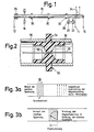
- Fig. 1 shows a magneto-strictive tube 10 with three electrical connections 12, 14, 16 which directly, z. B. low-attenuation via solder or welded connections, electrically connected to the tube 10.
- a first section of the tube 10 between the connections 14 and 16 is surrounded by a coil 24.
- a position magnet 18 and two reference magnets 20, 22 are also arranged along a second section of the tube 10, which lies between the connections 12 and 14.
- FIG. 1 shows a quartz plate 28 on which the two reference magnets 20, 22 are fastened at a fixed predetermined distance from one another.
- a current pulse is first generated, which generates a remanent circular magnetization between the connections 14 and 16 on the first section of the tube 10, which also serves as an electrical conductor and is surrounded by the coil 24.
- An electrical pulse is then generated with the aid of a pulse generator and runs between the connections 12 and 14 along the second section of the tube 10, which also serves as an electrical conductor.
- This electrical pulse triggers an ultrasonic pulse on the position magnet 18 and on each of the two reference magnets 20, 22. Due to the physical relationships explained at the outset, the ultrasound pulses lead to corresponding electrical signals between the connections of the coil 24.
- the length of the tube 10 is on the side facing away from the magnets 18, 20, 22 the coil 24 is selected so that the half-wave electrical signal, which is caused by an ultrasound pulse and has a first polarity, is immediately followed by a half-wave signal of opposite polarity, which is reflected by the reflection of the ultrasound pulse at the pipe end and through the return of this ultrasonic pulse is caused by the coil 24.
- a zero-crossing detector can be connected to the connections of the coil 24, with the aid of which a particularly exact transit time measurement for the ultrasound pulses is then made possible.
- the signal evaluation in the ultrasonic displacement sensor according to FIG. 1 can be carried out in the same way as described in the earlier application mentioned at the beginning (P 33 04 520.8).
- FIGS. 3a and 3b With regard to the special function of the ultrasound transducer according to the invention with the coil axially surrounding the tube 10, reference is made additionally to FIGS. 3a and 3b, where it is clearly illustrated that the running of the torsion front of an ultrasound pulse into the tangential or circular magnetized area of the magneto-strictive tube 10, which is surrounded by the coil 24 (FIG. 3a), according to FIG. 3b leads to a field change, on the basis of which an electrical voltage is induced in the coil 24.
- the direction of rotation of the torsion front or of the ultrasound pulse is indicated by an arrow B in FIG. 3a.
- FIG. 2 The construction according to FIG. 2 has proven itself with regard to the mechanical structure of the ultrasonic displacement sensor according to the invention. It is clear from this figure that the magnetostrictive tube 10 can be supported at suitable intervals with the aid of support rings 30, which have a relatively narrow central opening 32, which can pass through the tube 10 with little play will grip and define the annular shoulders 34, which serve to support sections 36 of a protective tube which surrounds the magneto-strictive tube 10.
- the support rings 30 and the sections 36 of the protective tube can for example consist of a suitable plastic.
- the support rings 30 are only indicated schematically as a support for the tube 10.
Description
Die Erfindung betrifft einen Ultraschall-Wegmesser zur linearen Wegmessung mit einem Rohr aus magneto-striktivem Material, mit einem bezüglich des Rohres beweglichen Magneten zur Erzeugung von als Positionssignale dienenden Ultraschall-Torisonsimpulsen in Abhängigkeit von längs des Rohres entlanglaufenden elektrischen Impulsen aus einem Impulsgenerator und mit einem an das Rohr angekoppelten Ultraschall Aufnehmer zum Umsetzen von in dem Rohr erzeugten Ultraschallimpulsen in elektrische Signale und mit einer Meßschaltung zur Ermittlung der Position des beweglichen Magneten in Abhängigkeit vom zeitlichen Abstand zwischen den aus den Positionssignalen erhaltenen Signalen und jeweils mindestens einem in Abhängigkeit vom Auftreten eines elektrischen Impulses erzeugten Bezugssignal.The invention relates to an ultrasonic displacement transducer for linear displacement measurement with a tube made of magneto-strictive material, with a magnet movable with respect to the tube for generating ultrasonic torison pulses serving as position signals as a function of electrical pulses from a pulse generator and with one running along the tube ultrasound transducer coupled to the tube for converting ultrasound pulses generated in the tube into electrical signals and with a measuring circuit for determining the position of the movable magnet as a function of the time interval between the signals obtained from the position signals and at least one as a function of the occurrence of an electrical one Impulse generated reference signal.
Ein derartiger Ultraschall-Wegmesser ist aus der US-PS 3 898 555 bekannt. Bei dem bekannten Wegmesser läuft durch das Innere des Rohres aus magneto-striktivem Material ein elektrischer Leiter, welchem elektrische Impulse vom Ausgang eines Impulsgenerators zugeführt werden. Diese elektrischen Impulse lösen an der Stelle des Rohres, an der sich der Magnet zur Erzeugung der Positionssignale befindet, jeweils einen Ultraschall-impuls aus, der aus einem Torsionswellen umfassenden Wellenpaket besteht, welches seinerseits von einem Wandler erfasst und in ein elektrisches Signal umgesetzt wird, dessen zeitlicher Abstand von einem Bezugssignal der Lage des beweglichen Magneten entspricht, wobei bei dem bekannten Wegmesser als Bezugssignale unmittelbar von den elektrischen Impulsen abgeleitete elektrische Signale verwendet werden. Der bekannte Wegmesser arbeitet dabei mit einem Ultraschall-Aufnehmer, welcher zwei Streifen aus magneto-striktivem Material aufweist, die tangential am Umfang des Rohres aus magneto-striktivem Material befestigt und die von Wandlerspulen umgeben sind. Durch diese Streifen werden zunächst die Torsionswellen des Rohres in Longitudinalwellen umgewandelt, da nur Longitudinalwellen mit Spulen direkt in ein elektrisches Signal umsetzbar sind, und anschliessend wird in der Spule ein elektrisches Ausgangssignal induziert.Such an ultrasonic odometer is known from US Pat. No. 3,898,555. In the known odometer, an electrical conductor runs through the interior of the tube made of magneto-strictive material, to which electrical pulses are supplied from the output of a pulse generator. These electrical pulses trigger an ultrasonic pulse at the location of the tube at which the magnet for generating the position signals is located, which pulse consists of a wave packet comprising torsion waves, which in turn is detected by a transducer and converted into an electrical signal, whose time interval from a reference signal corresponds to the position of the movable magnet, electrical signals derived directly from the electrical pulses being used as reference signals in the known distance measuring device. The known odometer works with an ultrasound transducer, which has two strips made of magneto-strictive material, which are attached tangentially to the circumference of the tube made of magneto-strictive material and which are surrounded by transducer coils. These strips first convert the torsional waves of the tube into longitudinal waves, since only longitudinal waves with coils can be converted directly into an electrical signal, and an electrical output signal is then induced in the coil.
Ein ähnlicher Ultraschall-Wegmesser, bei dem die Bezugssignale mit Hilfe eines in einem fest vorgegebenen Abstand von dem Wandler angeordneten weiteren, das Rohr umgebenden Magneten gewonnen werden, ist in der DE-OS 31 31 455 beschrieben. Auch dieser bekannte Ultraschall-Wegmesser arbeitet mit einem Ultraschall-Aufnehmer wie er vorstehend im Zusammenhang mit der US-PS 3 898 555 erläutert wurde. Der besondere Vorteil des Wegmessers gemäß DE-OS 31 31 455 besteht darin, daß temperaturabhängige Längen- und Laufzeitänderungen in dem Rohr aus magneto-striktivem Material dadurch kompensiert werden können, daß auch die Bezugssignale aus Ultraschallimpulsen gewonnen werden, die am Ort des feststehenden Bezugsmagneten erzeugt werden.A similar ultrasonic displacement sensor, in which the reference signals are obtained with the aid of a further magnet which surrounds the tube and is arranged at a fixed predetermined distance from the transducer, is described in DE-OS 31 31 455. This known ultrasonic displacement sensor also works with an ultrasonic transducer as was explained above in connection with US Pat. No. 3,898,555. The particular advantage of the odometer according to DE-OS 31 31 455 is that temperature-dependent changes in length and transit time in the tube made of magneto-strictive material can be compensated for in that the reference signals are obtained from ultrasound pulses generated at the location of the fixed reference magnet will.
Eine verbesserte Ausführungsform des Wegmessers gemäß DE-OS 31 31 455 ist ferner in einer früheren Anmeldung der Anmelderin (amtliches Aktenzeichen P 33 04 520.8) beschrieben, gemäß welcher zwei in einem fest vorgebenen Abstand voneinander angeordnete Bezugs- bzw. Referenzmagnete vorgesehen sind, mit deren Hilfe Ultraschallimpulse als Bezugssignale erzeugt werden, die so ausgewertet werden können, daß auch eine von der Temperatur oder der Alterung abhängige Drift der Parameter der Meßschaltung sehr weitgehend kompensiert werden kann. Auch der Wegmesser gemäß dieser früheren Anmeldung arbeitet wieder mit einem Ultraschall-Aufnehmer gemäß der US-PS 3 898 555.An improved embodiment of the odometer according to DE-OS 31 31 455 is further described in an earlier application by the applicant (official file number P 33 04 520.8), according to which two reference magnets are provided at a predetermined distance from one another, with their Ultrasound pulses are generated as reference signals, which can be evaluated in such a way that a drift of the parameters of the measuring circuit which is dependent on the temperature or aging can be very largely compensated for. The odometer according to this earlier application also works again with an ultrasound transducer according to US Pat. No. 3,898,555.
Bei allen bisher bekannten Ultraschall-Aufnehmern für Torsionsimpulse wird ein auf dem magneto-striktiven Rohr ankommender Torsionsimpuls in einen Longitudinalimpuls auf den magneto-striktiven Bändchen umgewandelt und der Longitudinalimpuls induziert aufgrund des umgekehrten Magnetostriktionseffekts (Villari-Effekt) in den die Bändchen umgebenden Spulen elektrische Signale. Es hat sich gezeigt, dass bei den bekannten Ultraschall-Wegmessern mit den beschriebenen Ultraschall-Aufnehmern durch Reflexion der Ultraschallimpulse am benachbarten Rohrende, insbesondere bei Verwendung von drei Magneten, nämlich zwei Referenzmagneten und einem Positionsmagnet, zahlreiche Echos entstehen, die sich mehr oder weniger stark überlappen und damit eine exakte Signalauswertung erschweren. Weiterhin hat es sich gezeigt, daß die Vergrößerung des Abstands zwischen den Referenzmagneten und/oder eine Dämpfung des an den Ultraschallaufnehmer angrenzenden Rohrendes relativ teuer ist und einen deutlich erhöhten Platzbedarf mit sich bringt, der dem praktischen Einsatz von Ultraschall-Wegmessern der betrachteten Art entgegensteht.In all previously known ultrasonic transducers for torsion pulses, a torsion pulse arriving on the magnetostrictive tube is converted into a longitudinal pulse on the magnetostrictive ribbon and the longitudinal pulse induces electrical signals in the coils surrounding the ribbon due to the reversed magnetostriction effect (Villari effect) . It has been shown that in the known ultrasonic displacement sensors with the described ultrasonic transducers, numerous echoes are generated by reflection of the ultrasonic pulses at the adjacent tube end, in particular when using three magnets, namely two reference magnets and one position magnet, which are more or less strong overlap and thus complicate an exact signal evaluation. Furthermore, it has been shown that increasing the distance between the reference magnets and / or damping the pipe end adjacent to the ultrasound transducer is relatively expensive and entails a significantly increased space requirement, which is in conflict with the practical use of ultrasound displacement meters of the type under consideration.
Ausgehend vom Stand der Technik und der vorstehend aufgezeigten Problematik liegt der Erfindung die Aufgabe zugrunde, einen Ultraschall-Wegmesser der eingangs angegebenen Art dahingehend zu verbessern, daß eine besonders präzise Erfassung der Zeitintervalle zwischen den längs des Rohres entlanglaufenden UltraschallImpulsen ermöglicht wird.Based on the prior art and the problems outlined above, the invention has for its object to improve an ultrasonic displacement sensor of the type specified in such a way that a particularly precise detection of the time intervals between the ultrasonic pulses running along the tube is made possible.
Diese Aufgabe wird gemäß der Erfindung dadurch gelöst, dass als Ultraschall-Aufnehmer zum direkten Nachweis von Torsionsimpulsen ein aufgrund von Remanenzerscheinungen zirkular magnetisiertes Teilstück des Rohres und eine dieses in axialer Richtung umgebende Spule vorsehen sind.This object is achieved according to the invention in that an ultrasound transducer for the direct detection of torsion pulses is provided by a portion of the tube which is magnetized circularly due to remanent phenomena and a coil surrounding it in the axial direction.
Die erfindungsgemäße Ausgestaltung eines Ultraschall-Wegmessers bzw. seines Ultraschall-Aufnehmers beruht auf folgenden Überlegungen :The design of an ultrasonic displacement sensor or its ultrasonic transducer according to the invention is based on the following considerations:
Durch den Positionsmagneten und gegebenenfalls den bzw. die Referenzmagneten wird längs des magneto-striktiven Rohres ein longitudinales magnetisches Feld erzeugt. Dies bedeutet, daß sich in dem Rohr die magnetischen Dipole bzw. ihre Gruppen, die Weiss'schen Bezirke in Längsrichtung des Rohres ausrichten. Wenn nun ein elektrischer Impuls an dem Rohr entlang bzw. bei im Inneren des Rohres angeordneten elektrischen Leiter durch dieses hindurchläuft, dann überlagert sich das zirkulare Magnetfeld, welches durch den elektrischen (Strom-) Impuls erzeugt wird, mit dem longitudinalen Feld des an der betreffenden Stelle befindlichen Permanent-Magneten zu einem schraubenförmigen Feld. Die magnetischen Dipole bzw. die Weiss'schen Bezirke klappen folglich in diese neue Feldrichtung, wodurch nach dem Joule-Effekt (Magnetostriktion) eine Verformung des Materials in Schraubenrichtung erfolgt. Hierdurch entsteht ein Ultraschallimpuls mit einer tangentialen bzw. zirkularen und einer longitudinalen Komponente, der sich mit Schallgeschwindigkeit nach beiden Seiten ausbreitet. Diese Torsionswellen wurden bisher durch beispielsweise in der US-PS 3 898 555 beschriebene Ultraschall-Aufnehmer in longitudinale Wellen umgewandelt und erst diese konnten mittels einer Spule in elektrische Signale umgewandelt werden.The position magnet and, if applicable, the reference magnet or magnets make it longitudinal generates a longitudinal magnetic field of the magneto-strictive tube. This means that the magnetic dipoles or their groups, the Weiss areas, are aligned in the longitudinal direction of the tube in the tube. If an electrical pulse now runs along the tube or with an electrical conductor arranged inside the tube, the circular magnetic field generated by the electrical (current) pulse is superimposed on the longitudinal field of the tube in question Place permanent magnets in a helical field. The magnetic dipoles or Weiss' districts consequently fold in this new field direction, which causes the material to deform in the screw direction after the Joule effect (magnetostriction). This creates an ultrasonic pulse with a tangential or circular and a longitudinal component, which propagates to both sides at the speed of sound. These torsional waves have so far been converted into longitudinal waves by ultrasound transducers, for example described in US Pat. No. 3,898,555, and only these could be converted into electrical signals by means of a coil.
Der wesentliche Punkt der vorliegenden Erfindung besteht nun darin, diese Torsionswellen direkt mit einer das Rohr in axialer Richtung umgebenden Spule, d. h. ohne Modenwandlung, nachzuweisen. Dies war mit den bisher bekannten Anordnungen nicht möglich, da die Torsionswellen in einer axial ausgerichteten Spule kein detektierbares elektrisches Signal erzeugten.The essential point of the present invention now consists in directly connecting these torsion shafts with a coil surrounding the tube in the axial direction, i. H. without changing the fashion. This was not possible with the previously known arrangements, since the torsion waves in an axially aligned coil did not generate a detectable electrical signal.
Der Nachweis gelingt nur, wenn das Teilstück des Rohres, das von der Spule umgeben ist, vor Ankunft einer Torsionswelle zirkular magnetisiert wird. Diese zirkulare Magnetisierung führt zu keinem Signal in der axial ausgerichteten Spule.The proof can only be obtained if the section of the tube which is surrounded by the coil is circularly magnetized before the arrival of a torsion wave. This circular magnetization does not result in a signal in the axially aligned coil.
Wenn nun ein Ultraschall-Impuls in Form eines Torsionsimpulses im Bereich der das Rohr umgebenden Spule des Ultraschall-Aufnehmers eine schraubenförmige mechanische Verformung des zirkular magnetisierten Rohres herbeiführt, dann werden einzelne Volumenelemente des Rohres verdreht und somit auch die darin enthaltenen magnetischen Dipole aus ihrer zirkularen Richtung herausgedreht, wodurch eine Feldänderung in Richtung der Spulenachse herbeigeführt wird, die dazu führt, dass in der Spule nach dem Induktionsgesetz ein elektrisches Signal induziert und folglich ein direkter Nachweis von Torsionswellen ohne Verwendung eines Modenwandlers möglich wird.If an ultrasonic pulse in the form of a torsion pulse causes a helical mechanical deformation of the circularly magnetized tube in the region of the coil of the ultrasonic transducer surrounding the tube, then individual volume elements of the tube are rotated and thus also the magnetic dipoles contained therein from their circular direction turned out, which causes a field change in the direction of the coil axis, which leads to an electrical signal being induced in the coil according to the law of induction and consequently direct detection of torsion waves being possible without using a mode converter.
Bei dem erfindungsgemässen Ultraschall-Wegmesser wird nun die zirkulare Magnetisierung des Rohres dadurch erreicht, dass die Remanenz des magneto-striktiven Materials ausgenützt wird, d. h. vor Auftreffen einer Torsionsfront wird das magneto-striktive Rohr durch geeignete Massnahmen vormagnetisiert, wobei aufgrund von Remanenzerscheinungen nach Entfernen des Vormagnetisierungsfeldes eine zirkulare Magnetisierung erhalten bleibt, die bei Auftreffen der Torsionsfront, wie oben beschrieben, eine axiale Komponente erhält.In the ultrasonic displacement sensor according to the invention, the circular magnetization of the tube is now achieved by taking advantage of the remanence of the magneto-strictive material, i. H. Before striking a torsion front, the magneto-strictive tube is premagnetized by suitable measures, whereby due to remanent phenomena after removal of the premagnetization field, a circular magnetization is retained which, as described above, receives an axial component when the torsion front strikes.
In Ausgestaltung der Erfindung hat es sich als vorteilhaft erwiesen, wenn Vormagnetisierungseinrichtungen vorgesehen sind, mit deren Hilfe in dem von der Spule umgebenen ersten Teilstück des Rohres vor jeder Messung mit Hilfe eines längs dieses Teilstücks entlanglaufenden Stromimpulses eine zirkulare Magnetisierung erzeugbar ist und wenn die Anschlüsse für den Impulsgenerator derart angeordnet sind, daß längs eines zweiten gegenüber dem ersten Teilstück versetzten Teilstücks des Rohres entlanglaufende elektrische Impulse erzeugbar sind.In an embodiment of the invention, it has proven to be advantageous if premagnetization devices are provided, with the aid of which a circular magnetization can be generated in the first section of the tube surrounded by the coil before each measurement with the aid of a current pulse running along this section and if the connections for the pulse generator are arranged in such a way that electrical pulses running along a second section of the tube which is offset with respect to the first section can be generated.
Der besondere Vorteil der erfindungsgemäßen Trennung des von den Ausgangsimpulsen beaufschlagten Teilstücks des magneto-striktiven Rohres und des von der Spule umgebenen Teilstücks des Rohres, an welches zur Erzeugung der zirkularen Magnetisierung des magneto-striktiven Materials besondere elektrische Impulse angelegt werden, die als Auffrischimpulse bezeichnet werden, besteht darin, daß zum Zeitpunkt der Messung in die Spule keine Störsignale induziert werden, die durch einen Ausgangsimpuls des Impulsgenerators hervorgerufen werden. Dabei wird hinsichtlich der Entstehung von Störsignalen von folgenden Überlegungen ausgegangen : Auch ein kleines longitudinales Magnetfeld im Bereich der Spule des Ultraschall-Aufnehmers, beispielsweise das Streufeld eines benachbarten Referenzmagneten, magnetisiert das magneto- striktive Material des Rohres in einem entsprechenden Umfang. Wenn unter diesen Voraussetzungen ein elektrischer Impuls des Impuls-Generators längs des Röhrchens entlangläuft, dann führt dies analog zur Erzeugung des Meßsignals zu einem Umklappen bzw. zu einer Richtungsänderung der magnetischen Dipole. Da diese Änderung der Richtung des Magnetfeldes von der Spule des erfindungsgemäßen Ultraschall-Aufnehmers ohne die verlustbehafteten Mechanismen der Magnetostriktion bzw. des Villari-Effektes direkt erfasst wird, ist folglich die induzierte Störspannung unter Umständen um eine ganze Größenordnung höher als ein durch einen auszuwertenden Ultraschall-Impuls aufgrund des Villari-Effektes erzeugtes Nutzsignal. Die dadurch im Ultraschall-Aufnehmer erzeugten Schwingungen können folglich die genaue Messung der Positions- und der mit Hilfe von Referenzmagneten erzeugten Bezugssignale erheblich beeinträchtigen. Dieser Nachteil wird vermieden, wenn die bei einer Messung von dem Impulsgenerator erzeugten elektrischen Impulse nicht an dem Teilstück des magneto-striktiven Rohres entlangfließen, welches von der Spule umgeben wird, und wenn die zirkulare Magnetisierung in dem von der Spule umgebenen Teilstück mittels besonderer Auffrischimpulse zwischen den einzelnen Messungen erzeugt wird.The particular advantage of the separation according to the invention of the portion of the magnetostrictive tube acted upon by the output pulses and the portion of the tube surrounded by the coil, to which special electrical pulses, which are referred to as refreshing pulses, are applied in order to generate the circular magnetization of the magnetostrictive material , is that at the time of measurement, no interference signals are induced in the coil, which are caused by an output pulse of the pulse generator. With regard to the generation of interference signals, the following considerations are assumed: Even a small longitudinal magnetic field in the area of the coil of the ultrasound transducer, for example the stray field of an adjacent reference magnet, magnetizes the magnetostrictive material of the tube to a corresponding extent. If, under these conditions, an electrical pulse of the pulse generator runs along the tube, this leads to a flipping or a change of direction of the magnetic dipoles analogously to the generation of the measurement signal. Since this change in the direction of the magnetic field is detected directly by the coil of the ultrasound transducer according to the invention without the lossy mechanisms of magnetostriction or the Villari effect, the induced interference voltage may therefore be an order of magnitude higher than that caused by an ultrasound to be evaluated. Useful signal generated due to the Villari effect. The vibrations thereby generated in the ultrasound transducer can consequently significantly impair the precise measurement of the position signals and the reference signals generated with the aid of reference magnets. This disadvantage is avoided if the electrical pulses generated by the pulse generator during a measurement do not flow along the section of the magnetostrictive tube which is surrounded by the coil, and if the circular magnetization in the section surrounded by the coil by means of special refreshing pulses between the individual measurements is generated.
Was die Erzeugung der Bezugssignale anbelangt, so kann der erfindungsgemäße Ultraschall-Wegmesser, wie die früheren Systeme, mit einem oder mit zwei Referenzmagneten oder wie der Wegmesser gemäß US-PS 3 898 555 mit den Ausgangsimpulsen des Impulsgenerators selbst arbeiten. Die prinzipiellen Vorteile des erfindungsgemäßen Ultraschall-Aufnehmers werden hierdurch nicht beeinflusst. Vorteilhafte Ausgestaltungen der Erfindung sind Gegenstand von Unteransprüchen.As far as the generation of the reference signals is concerned, the ultrasonic displacement sensor according to the invention, like the previous systems, can be equipped with one or two reference magnets or the like The odometer according to US Pat. No. 3,898,555 works with the output pulses of the pulse generator itself. The basic advantages of the ultrasound transducer according to the invention are not affected by this. Advantageous embodiments of the invention are the subject of dependent claims.
Weitere Einzelheiten und Vorteile der Erfindung werden nachstehend anhand von Zeichnungen noch näher erläutert.Further details and advantages of the invention are explained in more detail below with reference to drawings.
Es zeigen :
- Fig. 1 eine schematische Seitenansicht der wesentlichen Teile einer bevorzugten Ausführungsform eines Ultraschall-Wegmessers gemäß der Erfindung ;
- Fig. 2 einen vergrößerten Teilquerschnitt durch eine Halterung für das magnetostriktive Rohr des Ultraschall-Wegmessers gemäß Fig. 1 und
- Fig. 3a und Fig. 3b schematische Darstellungen zur Erläuterung der physikalischen Grundlagen des Ultraschall-Wegmessers gemäß Fig. 1 und 2.
- Figure 1 is a schematic side view of the essential parts of a preferred embodiment of an ultrasonic displacement sensor according to the invention.
- Fig. 2 is an enlarged partial cross section through a holder for the magnetostrictive tube of the ultrasonic displacement sensor according to FIG. 1 and
- 3a and 3b are schematic representations to explain the physical principles of the ultrasonic displacement sensor according to FIGS. 1 and 2.
Im einzelnen zeigt Fig. 1 ein magneto-striktives Rohr 10 mit drei elektrischen Anschlüssen 12, 14, 16, die direkt, z. B. über Löt- oder Schweißverbindungen dämpfungsarm, elektrisch leitend mit dem Rohr 10 verbunden sind. Ein erstes Teilstück des Rohres 10 zwischen den Anschlüssen 14 und 16 ist von einer Spule 24 umgeben. Längs eines zweiten Teilstücks des Rohres 10, welches zwischen den Anschlüssen 12 und 14 liegt, sind ferner ein Positionsmagnet 18 und zwei Referenzmagnete 20, 22 angeordnet.In particular, Fig. 1 shows a magneto-
Ferner ist das an den Anschluß 12 angrenzende Ende des Rohres 10 von einer nur schematisch angedeuteten Dämpfungsvorrichtung 26 umgeben, die beispielsweise aus mehreren Gummischeiben unterschiedlicher Härte bestehen kann. Schließlich zeigt Fig. 1 eine Quarzplatte 28, auf der die beiden Referenzmagneten 20, 22 in einem fest vorgegebenen Abstand voneinander befestigt sind.Furthermore, the end of the
Beim Arbeiten mit dem Ultraschall-Wegmesser gemäß Fig. 1 wird zunächst ein Stromimpuls erzeugt, welcher zwischen den Anschlüssen 14 und 16 an dem gleichzeitig als elektrischer Leiter dienenden, von der Spule 24 umgebenen ersten Teilstück des Rohres 10 eine remanente zirkulare Magnetisierung erzeugt. Anschließend wird mit Hilfe eines Impulsgenerators ein elektrischer Impuls erzeugt, der zwischen den Anschlüssen 12 und 14 an dem ebenfalls als elektrischer Leiter dienenden zweiten Teilstück des Rohres 10 entlangläuft. Dieser elektrische Impuls löst am Positionsmagnet 18 und an jedem der beiden Referenzmagneten 20, 22 jeweils einen Ultraschall- Impuls aus. Die Ultraschall-Impulse führen aufgrund der eingangs erläuterten physikalischen Zusammenhänge zu entsprechenden elektrischen Signalen zwischen den Anschlüssen der Spule 24. Dabei ist es in Ausgestaltung der Erfindung besonders vorteilhaft, wenn die Länge des Rohres 10 auf der von den Magneten 18, 20, 22 abgewandten Seite der Spule 24 so gewählt wird, daß sich an das halbwellenförmige elektrische Signal, welches durch einen Ultraschall-Impuls hervorgerufen wird und eine erste Polarität aufweist, sofort ein halbwellenförmiges Signal entgegengesetzter Polarität anschließt, welches durch die Reflexion des betreffenden Ultraschall-Impulses am Rohrende und durch das Zurücklaufen dieses Ultraschall-Impulses durch die Spule 24 hervorgerufen wird. Bei dieser Ausgestaltung kann nämlich mit den Anschlüssen der Spule 24 ein NullDurchgangsdetektor verbunden werden, mit dessen Hilfe dann eine besonders exakte Laufzeitmessung für die Ultraschall-Impulse ermöglicht wird. Im übrigen kann die Signalauswertung bei dem Ultraschall-Wegmesser gemäß Fig. 1 in derselben Weise erfolgen, wie dies in der eingangs erwähnten, früheren Anmeldung (P 33 04 520.8) beschrieben ist.1, a current pulse is first generated, which generates a remanent circular magnetization between the
Bezüglich der speziellen Funktion des erfindungsgemäßen Ultraschall-Aufnehmers mit der das Rohr 10 axial umgebenden Spule wird jedoch ergänzend auf Fig. 3a und Fig. 3b verwiesen, wo anschaulich verdeutlicht ist, daß das Hineinlaufen der Torsionsfront eines Ultraschall-Impulses in den tangential bzw. zirkular magnetisierten Bereich des magneto-striktiven Rohres 10, der von der Spule 24 umgeben ist (Fig. 3a), gemäß Fig. 3b zu einer Feldänderung führt, aufgrund welcher eine elektrische Spannung in die Spule 24 induziert wird. Dabei ist die Laufrichtung der Torsionsfront bzw. des Ultraschallimpulses in Fig. 3a durch einen Pfeil B angedeutet. Anhand von Fig. 3a und 3b kann man sich ferner klarmachen, daß bei einer Reflexion der Torsionsfront hinter dem Bereich mit tangentialer Ausrichtung der Magnetisierung, die durch einen Stromstoß zwischen den Anschlüssen 14 und 16 bewirkt wurde, der Verlauf der mechanischen Spannung in der Torsionsfront derart um 180° gedreht ist, daß der zurücklaufende Ultraschallimpuls bzw. das Echo des Ultraschallimpulses eine Feldänderung in die entgegengesetzte Richtung hervorruft und folglich ein elektrisches Signal in der Spule 24 zur Folge hat, dessen Polarität zur Polarität des zuerst in der Spule 24 erzeugten Signals entgegengesetzt ist. Es ist daher, wie oben erwähnt, bei geeigneter Bemessung der Rohrlänge hinter der Spule 24 möglich, aufgrund eines Ultraschall-Impulses und seines Echos zwei halbwellenförmige elektrische Signale entgegengesetzter Polarität zu erhalten und den Null-Durchgang zwischen den Signalen zu erfassen, wodurch sich außerordentlich präzise Laufzeitmessungen durchführen lassen, da der Null-Durchgang durch Verzerrungen und Amplitudenänderungen der Halbwellen praktisch nicht beeinflusst wird.With regard to the special function of the ultrasound transducer according to the invention with the coil axially surrounding the
Hinsichtlich des mechanischen Aufbaus des erfindungsgemäßen Ultraschall-Wegmessers hat sich die Konstruktion gemäß Fig. 2 bewährt. Aus dieser Figur wird deutlich, daß das magneto- striktive Rohr 10 in geeigneten Abständen mit Hilfe von Stützringen 30 abgestützt werden kann, die eine relativ enge Mittelöffnung 32 aufweisen, die von dem Rohr 10 mit geringem Spiel durchgriffen wird und die gleichzeitig ringförmige Schultern 34 definieren, die der Abstützung von Teilstücken 36 eines Schutzrohres dienen, welches das magneto-striktive Rohr 10 umgibt. Die Stützringe 30 und die Teilstücke 36 des Schutzrohrs können beispielsweise aus einem geeigneten Kunststoff bestehen. In Fig. 1 sind die Stützringe 30 lediglich schematisch als Auflager für das Rohr 10 angedeutet.The construction according to FIG. 2 has proven itself with regard to the mechanical structure of the ultrasonic displacement sensor according to the invention. It is clear from this figure that the
Damit jede Störung der Ausbreitung der Ultraschallimpulse längs des magneto-striktiven Rohres 10, insbesondere die Entstehung von unerwünschten Echos, im Bereich der Anschlußpunkte der elektrischen Anschlüsse 12, 14, 16 vermieden wird, verwendet man erfindungsgemäß für diese elektrischen Anschlüsse sehr feine und leichte Drähte, die vorzugsweise durch Punktschweißen an dem magneto-striktiven Rohr 10 befestigt werden. Es hat sich nämlich gezeigt, daß bei der Verwendung von dünnen Anschlußdrähten, die durch Punktschweißen oder Laserschweißen an dem Rohr 10 befestigt werden, keine Störung der Ausbreitung der Ultraschallimpulse längs des Rohres eintritt, während die Punktschweißverbindung andererseits auch im Dauerbetrieb zuverlässig hält, so daß jederzeit ein störungsfreier und widerstandsarmer Übergang der elektrischen Signale auf das magneto-striktive Rohr 10 gewährleistet ist.So that any interference with the propagation of the ultrasonic pulses along the
Claims (9)
Applications Claiming Priority (2)
| Application Number | Priority Date | Filing Date | Title |
|---|---|---|---|
| DE3343310 | 1983-11-30 | ||
| DE19833343310 DE3343310A1 (en) | 1983-11-30 | 1983-11-30 | ULTRASONIC GAUGE |
Publications (2)
| Publication Number | Publication Date |
|---|---|
| EP0149745A1 EP0149745A1 (en) | 1985-07-31 |
| EP0149745B1 true EP0149745B1 (en) | 1988-08-17 |
Family
ID=6215667
Family Applications (1)
| Application Number | Title | Priority Date | Filing Date |
|---|---|---|---|
| EP84113720A Expired EP0149745B1 (en) | 1983-11-30 | 1984-11-14 | Ultrasonic position measuring device |
Country Status (5)
| Country | Link |
|---|---|
| US (1) | US4678993A (en) |
| EP (1) | EP0149745B1 (en) |
| JP (1) | JPS60140109A (en) |
| BR (1) | BR8406088A (en) |
| DE (2) | DE3343310A1 (en) |
Families Citing this family (52)
| Publication number | Priority date | Publication date | Assignee | Title |
|---|---|---|---|---|
| DE3629174A1 (en) * | 1986-08-28 | 1988-03-10 | Ktv Systemtechnik Gmbh | Device for measuring the wall thickness of pipes (tubes) |
| JPS63217224A (en) * | 1987-03-06 | 1988-09-09 | Sankyo Boeki Kk | Displacement detecting device |
| JPS63238415A (en) * | 1987-03-26 | 1988-10-04 | Hitachi Constr Mach Co Ltd | Stroke detector of cylinder apparatus |
| US4943773A (en) * | 1987-09-24 | 1990-07-24 | Magnetek Controls | Magnetostrictive linear displacement transducer having preselected zero crossing detector |
| DE3839194A1 (en) * | 1988-11-19 | 1990-05-23 | Heidenhain Gmbh Dr Johannes | Incremental position measuring device for measuring the relative position of two objects by means of ultrasonic waves |
| US4952873A (en) * | 1989-09-11 | 1990-08-28 | Mts Systems Corporation | Compact head, signal enhancing magnetostrictive transducer |
| US4970464A (en) * | 1989-09-14 | 1990-11-13 | Jack Williams | Linear position-displacement magnetostrictive transducer having multiple cylindrical electromagnets for generating flux, each electromagnet having a centered passageway for relative travel along the same magnetostrictive waveguide |
| WO1991007638A1 (en) * | 1989-11-17 | 1991-05-30 | Kaunassky Politekhnichesky Institut | Device for measuring linear movements of an object |
| US5050135A (en) * | 1989-12-20 | 1991-09-17 | Unico, Inc. | Magnetostrictive multiple position sensing device |
| EP0471073A4 (en) * | 1990-03-06 | 1994-03-21 | Hitachi Construction Machinery | Cylinder device. |
| US5311124A (en) * | 1991-03-11 | 1994-05-10 | Mts Systems Corporation | Emulated analog output magnetostrictive position transducer with set point selection |
| US5206586A (en) * | 1991-03-11 | 1993-04-27 | Mts Systems Corporation | Magnetostrictive position transducer having square-wave-in-quadrature-output |
| US5196791A (en) * | 1991-09-27 | 1993-03-23 | Magnetek Controls | Magnetostrictive linear position detector and a dual pole position magnet therefor |
| FR2689895A1 (en) * | 1992-04-10 | 1993-10-15 | Chryso | Process for the preparation of polyoxyalkyl amines |
| US5473245A (en) * | 1993-11-04 | 1995-12-05 | K-Tek Corporation | Magnetostrictive linear displacement transmitter having improved piezoelectric sensor |
| DE19530892C2 (en) * | 1995-08-14 | 1999-09-30 | Mannesmann Ag | Measuring device for contactless determination of the distance covered and the speed of elements moving on a route |
| US5717330A (en) * | 1996-03-07 | 1998-02-10 | Moreau; Terence J. | Magnetostrictive linear displacement transducer utilizing axial strain pulses |
| US5714881A (en) * | 1996-03-12 | 1998-02-03 | Patriot Sensors And Controls Corporation | Position measurement apparatus using wire waveguide in shock resistant suspension |
| US5923164A (en) * | 1996-10-15 | 1999-07-13 | Balluff, Inc. | Apparatus and method for automatically tuning the gain of an amplifier |
| US5804961A (en) * | 1996-10-28 | 1998-09-08 | Patriot Sensors & Control, Corp. | Magnetostrictive waveguide position measurement apparatus using piezoelectric sensor |
| US5986449A (en) * | 1997-05-01 | 1999-11-16 | Patroit Sensors And Controls Corporation | Self-contained liquid level detection apparatus with substantially constant cross-section outer tube |
| US6356071B1 (en) | 1997-05-02 | 2002-03-12 | Patriot Sensors & Controls, Inc. | Self-contained position detection apparatus |
| US5929763A (en) * | 1997-06-27 | 1999-07-27 | Patriot Sensors And Controls | Liquid level detection apparatus with flexible outer housing |
| US5998991A (en) * | 1997-11-10 | 1999-12-07 | Patriot Sensors And Controls | Pickupless magnetostrictive position measurement apparatus |
| DE19753805C2 (en) * | 1997-12-03 | 1999-09-30 | Asm Automation Sensorik Messte | Storage for waveguides for the transmission of mechanical waves and method of manufacture |
| US6167756B1 (en) | 1998-03-02 | 2001-01-02 | Patriot Sensors & Controls, Inc. | Pivotal float for liquid level detection apparatus |
| GB9806923D0 (en) * | 1998-03-31 | 1998-05-27 | Flying Null Ltd | Position sensing |
| US6232769B1 (en) | 1998-06-16 | 2001-05-15 | Balluff, Inc. | Modular waveguide assembly for a position sensor and method for making the same |
| US6600962B1 (en) * | 1998-10-05 | 2003-07-29 | Mts Systems Corporation | Sensor controller |
| US20040097996A1 (en) | 1999-10-05 | 2004-05-20 | Omnisonics Medical Technologies, Inc. | Apparatus and method of removing occlusions using an ultrasonic medical device operating in a transverse mode |
| US6434516B1 (en) | 1999-11-12 | 2002-08-13 | Balluff, Inc. | Method and apparatus for synthesizing an incremental signal |
| DE10108925B4 (en) | 2001-02-23 | 2008-09-11 | Asm Automation Sensorik Messtechnik Gmbh | Magneto-strictive measuring device |
| SE523803C2 (en) * | 2001-09-18 | 2004-05-18 | Hagloef Sweden Ab | Klave for measuring tree diameter |
| US6757635B2 (en) * | 2001-12-12 | 2004-06-29 | Balluff, Inc. | Programmed method and apparatus for quadrature output sensors |
| GB2385229B (en) * | 2002-02-05 | 2005-04-20 | Pii Ltd | Electromagnetic acoustic transducers |
| US6954685B2 (en) * | 2002-04-23 | 2005-10-11 | Lord Corporation | Aircraft vehicular propulsion system monitoring device and method |
| US7925392B2 (en) * | 2002-04-23 | 2011-04-12 | Lord Corporation | Aircraft vehicular propulsion system monitoring device and method |
| CA2524264A1 (en) | 2003-05-06 | 2004-11-18 | Sri International | Systems and methods of recording piston rod position information in a magnetic layer on a piston rod |
| US6919779B2 (en) * | 2003-09-03 | 2005-07-19 | Mts Systems Corporation | Folded magnetostrictive wave guide |
| WO2005083626A2 (en) * | 2003-10-14 | 2005-09-09 | Lord Corporation | Magnetostrictive sensor for measuring distances |
| US7794414B2 (en) | 2004-02-09 | 2010-09-14 | Emigrant Bank, N.A. | Apparatus and method for an ultrasonic medical device operating in torsional and transverse modes |
| US7259553B2 (en) | 2005-04-13 | 2007-08-21 | Sri International | System and method of magnetically sensing position of a moving component |
| DE102005061730B4 (en) * | 2005-11-18 | 2009-07-23 | Tr Electronic Gmbh | Device for moving a piston |
| JP2013519882A (en) * | 2010-02-11 | 2013-05-30 | エスアールアイ インターナショナル | Displacement measurement system and method using magnetic encoding |
| GB201104345D0 (en) * | 2011-03-15 | 2011-04-27 | Pulse Structural Monitoring Ltd | In-situ self-calibrating strain sensor |
| WO2013074331A1 (en) | 2011-11-17 | 2013-05-23 | Abb Inc. | Improved piezo sensor |
| DE102013009221A1 (en) | 2013-05-31 | 2014-12-04 | Fafnir Gmbh | Device for magnetostrictive position measurement |
| CN103322950B (en) * | 2013-06-21 | 2017-02-08 | 中国电子科技集团公司第四十五研究所 | Edge detection method based on ultrasonic waves |
| CN109620681A (en) * | 2018-12-10 | 2019-04-16 | 上海荣泰健康科技股份有限公司 | Massage armchair shoulder position detection method, system and massage armchair |
| WO2021152482A1 (en) | 2020-01-27 | 2021-08-05 | Mts Sensor Technologie Gmbh & Co. Kg | Magnetostrictive position measurement using frequency domain analysis |
| DK3992583T3 (en) | 2020-11-03 | 2023-02-27 | Sick Atech Gmbh | MAGNETO STRICTIVE DISTANCE SENSOR |
| CN112834069B (en) * | 2021-01-07 | 2023-01-24 | 河北工业大学 | Ni-Cr alloy temperature sensor based on magnetostrictive torsional wave |
Family Cites Families (8)
| Publication number | Priority date | Publication date | Assignee | Title |
|---|---|---|---|---|
| US3898555A (en) * | 1973-12-19 | 1975-08-05 | Tempo Instr Inc | Linear distance measuring device using a moveable magnet interacting with a sonic waveguide |
| US4071818A (en) * | 1975-11-03 | 1978-01-31 | Combustion Engineering, Inc. | Magnetostrictive position indicator |
| DE2833369C3 (en) * | 1978-07-29 | 1985-05-30 | Dr. Johannes Heidenhain Gmbh, 8225 Traunreut | Arrangement for incremental measurement of the relative position of two objects by means of ultrasonic waves |
| DE2837014C3 (en) * | 1978-08-24 | 1981-02-26 | Olympia Werke Ag, 2940 Wilhelmshaven | Arrangement for measuring the distance between the change in distance and the speed of change in distance between two bodies which can be moved relative to one another on a predetermined path of movement |
| US4319189A (en) * | 1979-06-29 | 1982-03-09 | International Business Machines Corporation | Magnetoacoustic position sensor employing pulse code sequence generators and detectors |
| JPS5722512A (en) * | 1980-07-16 | 1982-02-05 | Copal Co Ltd | Position detecting device |
| GB2098731A (en) | 1981-05-12 | 1982-11-24 | Planters Powergrind | Determining linear measurement |
| DE3131455A1 (en) * | 1981-08-08 | 1983-03-24 | Gebhard Balluff GmbH & Co Feinmechanische Erzeugnisse, 7303 Neuhausen | Magnetostrictive displacement sensor |
-
1983
- 1983-11-30 DE DE19833343310 patent/DE3343310A1/en active Granted
-
1984
- 1984-11-14 EP EP84113720A patent/EP0149745B1/en not_active Expired
- 1984-11-14 DE DE8484113720T patent/DE3473507D1/en not_active Expired
- 1984-11-20 US US06/673,473 patent/US4678993A/en not_active Expired - Fee Related
- 1984-11-29 JP JP59250651A patent/JPS60140109A/en active Pending
- 1984-11-29 BR BR8406088A patent/BR8406088A/en not_active IP Right Cessation
Also Published As
| Publication number | Publication date |
|---|---|
| DE3343310C2 (en) | 1987-01-29 |
| DE3473507D1 (en) | 1988-09-22 |
| DE3343310A1 (en) | 1985-06-05 |
| US4678993A (en) | 1987-07-07 |
| BR8406088A (en) | 1985-09-24 |
| JPS60140109A (en) | 1985-07-25 |
| EP0149745A1 (en) | 1985-07-31 |
Similar Documents
| Publication | Publication Date | Title |
|---|---|---|
| EP0149745B1 (en) | Ultrasonic position measuring device | |
| DE2356199C2 (en) | Device for determining coordinates on a surface | |
| DE2933557C2 (en) | Transmitter for non-contact distance or speed measurement | |
| EP0797105B1 (en) | Method for measuring the time of flight of electric, electromagnetic or acoustic signals | |
| EP0452531B1 (en) | Electric measuring device for determining the propagation time of an electrical signal | |
| DE2924590A1 (en) | DEVICE AND METHOD FOR DETECTING THE SPEED AND ANGLE POSITION OF A ROTATING SHAFT | |
| DE4431164C2 (en) | Semiconductor pulse generator | |
| DE2643383C3 (en) | Switching arrangement for an ultrasonic pulse echo method for measuring the thickness or the speed of sound in test pieces | |
| DE3544198A1 (en) | Vortex flow meter | |
| EP0200183A2 (en) | Method and device for non-destructive testing of ferromagnetic material | |
| DE3309089A1 (en) | DEVICE FOR DETERMINING THE POSITION OF A MOVING BODY, IN PARTICULAR WITH A NUCLEAR REACTOR | |
| DE102007033745B4 (en) | Inductive speed detection | |
| DE3131455A1 (en) | Magnetostrictive displacement sensor | |
| DE60003263T2 (en) | Magnetostrictive position measuring transducer with high measuring accuracy | |
| EP0557671B1 (en) | Vortex flow meter | |
| EP0370174A1 (en) | Inductive rotation sensor for a vane-type flow meter | |
| DE1773777C3 (en) | Device for measuring the speed of a fluid flow | |
| DE3304520A1 (en) | ULTRASONIC GAUGE | |
| DE3408478C1 (en) | Device for the incremental measurement of rotation angles or length | |
| DE2827985C2 (en) | Flow meter | |
| DE102004025388B4 (en) | Determining position and movement parameters of object, e.g. machine part, by determining movement parameters that have differential relation to position and/or first movement parameters | |
| DE102007001821B4 (en) | Inductive proximity switch | |
| DE2837014C3 (en) | Arrangement for measuring the distance between the change in distance and the speed of change in distance between two bodies which can be moved relative to one another on a predetermined path of movement | |
| DE3104768C2 (en) | Acoustic transmission link | |
| DE3140302A1 (en) | MAGNETIC POLARIZATION LEVER |
Legal Events
| Date | Code | Title | Description |
|---|---|---|---|
| PUAI | Public reference made under article 153(3) epc to a published international application that has entered the european phase |
Free format text: ORIGINAL CODE: 0009012 |
|
| AK | Designated contracting states |
Designated state(s): CH DE FR GB IT LI |
|
| 17P | Request for examination filed |
Effective date: 19850613 |
|
| 17Q | First examination report despatched |
Effective date: 19861204 |
|
| GRAA | (expected) grant |
Free format text: ORIGINAL CODE: 0009210 |
|
| AK | Designated contracting states |
Kind code of ref document: B1 Designated state(s): CH DE FR GB IT LI |
|
| GBT | Gb: translation of ep patent filed (gb section 77(6)(a)/1977) | ||
| REF | Corresponds to: |
Ref document number: 3473507 Country of ref document: DE Date of ref document: 19880922 |
|
| ET | Fr: translation filed | ||
| ITF | It: translation for a ep patent filed |
Owner name: JACOBACCI & PERANI S.P.A. |
|
| PLBE | No opposition filed within time limit |
Free format text: ORIGINAL CODE: 0009261 |
|
| STAA | Information on the status of an ep patent application or granted ep patent |
Free format text: STATUS: NO OPPOSITION FILED WITHIN TIME LIMIT |
|
| 26N | No opposition filed | ||
| REG | Reference to a national code |
Ref country code: GB Ref legal event code: 727 |
|
| REG | Reference to a national code |
Ref country code: GB Ref legal event code: 727A |
|
| REG | Reference to a national code |
Ref country code: GB Ref legal event code: 727B |
|
| REG | Reference to a national code |
Ref country code: GB Ref legal event code: SP |
|
| ITTA | It: last paid annual fee | ||
| PGFP | Annual fee paid to national office [announced via postgrant information from national office to epo] |
Ref country code: FR Payment date: 19931027 Year of fee payment: 10 |
|
| PGFP | Annual fee paid to national office [announced via postgrant information from national office to epo] |
Ref country code: CH Payment date: 19931028 Year of fee payment: 10 |
|
| PGFP | Annual fee paid to national office [announced via postgrant information from national office to epo] |
Ref country code: GB Payment date: 19931108 Year of fee payment: 10 |
|
| PGFP | Annual fee paid to national office [announced via postgrant information from national office to epo] |
Ref country code: DE Payment date: 19931217 Year of fee payment: 10 |
|
| PG25 | Lapsed in a contracting state [announced via postgrant information from national office to epo] |
Ref country code: GB Effective date: 19941114 |
|
| PG25 | Lapsed in a contracting state [announced via postgrant information from national office to epo] |
Ref country code: LI Effective date: 19941130 Ref country code: CH Effective date: 19941130 |
|
| GBPC | Gb: european patent ceased through non-payment of renewal fee |
Effective date: 19941114 |
|
| PG25 | Lapsed in a contracting state [announced via postgrant information from national office to epo] |
Ref country code: FR Effective date: 19950731 |
|
| REG | Reference to a national code |
Ref country code: CH Ref legal event code: PL |
|
| PG25 | Lapsed in a contracting state [announced via postgrant information from national office to epo] |
Ref country code: DE Effective date: 19950801 |
|
| REG | Reference to a national code |
Ref country code: FR Ref legal event code: ST |