EP0149296A2 - Exercising toy arrangement for infants - Google Patents
Exercising toy arrangement for infants Download PDFInfo
- Publication number
- EP0149296A2 EP0149296A2 EP84301073A EP84301073A EP0149296A2 EP 0149296 A2 EP0149296 A2 EP 0149296A2 EP 84301073 A EP84301073 A EP 84301073A EP 84301073 A EP84301073 A EP 84301073A EP 0149296 A2 EP0149296 A2 EP 0149296A2
- Authority
- EP
- European Patent Office
- Prior art keywords
- toy
- extensions
- arrangement
- elongated element
- straps
- Prior art date
- Legal status (The legal status is an assumption and is not a legal conclusion. Google has not performed a legal analysis and makes no representation as to the accuracy of the status listed.)
- Withdrawn
Links
Images

Classifications
-
- A—HUMAN NECESSITIES
- A63—SPORTS; GAMES; AMUSEMENTS
- A63H—TOYS, e.g. TOPS, DOLLS, HOOPS OR BUILDING BLOCKS
- A63H1/00—Tops
- A63H1/02—Tops with detachable winding devices
- A63H1/04—Tops with detachable winding devices with string or band winding devices
-
- A—HUMAN NECESSITIES
- A63—SPORTS; GAMES; AMUSEMENTS
- A63H—TOYS, e.g. TOPS, DOLLS, HOOPS OR BUILDING BLOCKS
- A63H33/00—Other toys
- A63H33/006—Infant exercisers, e.g. for attachment to a crib
Definitions
- the present invention relates to toys in general, and more particularly to an exercising toy arrangement for use by infants or small children.
- an inflatable overhead crib gym toy including a central body and.two axial extensions, which toy is to be mounted on the opposite side rails of the crib by means of mounting straps, such as to extend substantially horizontally across the crib above the child.
- Two handles in the form of actuating straps are mounted on the extensions, thus enabling the child to pull on these actuating straps with resultant up-and-down movement of the toy arrangement.
- This particular arrangement can also be instrumental in helping the infant in developing the strength and coordination needed for the child to sit up, with the aid of the actuating straps, from the prostrate position.
- this particular toy or exercise arrangement leaves something to be desired in terms of variety of activities and motions permitted by its construction, and thus of attractiveness to the child.
- a further object of the present invention is so to construct the arrangement of the type here under consideration as to increase the amount of activities in which the child can engage and thus the range of different muscular movements which the child can perform while playing with the toy arrangement.
- a concomitant object of the present invention is to devise a toy exercising arrangement which is simple in construction, inexpensive and safe to use, attractive to the child for a long time, and generally reliable in operation.
- an exercising arrangement particularly for use by infants, which arrangement is to be mounted on spaced supporting structures, such as side rails of a crib, wherein the arrangement comprises an elongated body centered on a main axis and having longitudinally spaced end portions; means for mounting the body on the supporting structures for angular displacement about the main axis, the mounting means including two mounting straps each secured to one of the end portions of the body and detachably connected to one of the supporting structures in a use condition of the exercising arrangement in which one portion of the body is on top and another portion of the body is at the bottom of the body; and at least one elongated element connected to the body at a circumferential spacing from the other portion of the body in the use position and operative for turning the body about the main axis when pulled substantially downwardly.
- the elongated element is flexible. It is particularly advantageous when the flexible elongated element is connected to the one portion of the body, that is, to that portion that is situated on top in the use condition. In this case, the flexible elongated element is partially wrapped around, and partially depends from, the body, thus increasing the possible range of angular displacement of the body about its main axis.
- a particularly advantageous construction according to the present invention is obtained when the arrangement further comprises an additional elongated element similar to the aforementioned one elongated element and connected to the body at substantially the same circumferential spacing from the other portion of the body as the one elongated element, but disposed in the opposite circumferential direction than the one elongated element.
- this expedient it is possible to so arrange the elongated elements that each of them will depend from a different side of 3 the body, so that pulling on one of them will result in displacement in one circumferential direction, while the pulling on the other elongated element will result in displacement in the opposite circumferential direction.
- the elongated body includes a central body section of a larger diameter, and two extensions of a smaller diameter extending axially beyond the central body section to form continuations therefor. Then, it is advantageous when the one elongated element is connected to one of the extensions, and the additional elongated element is connected to the other of the extensions. It is particularly advantageous when the elongated element, or each of the elongated elements, is constructed as an actuating strap.
- Fig. 4 is an enlarged, partially sectioned, view of a detail of the toy exercising arrangement, the section being taken on line 4-4 of Fig. 2.
- the exercising device 10 is soft and inflatable and constructed as a nursery toy that is useful for encouraging children, particularly infants, to develop their motor skills by performing exercise-type manual movements using the toy 10 while playing with the same.
- the exercise device or nursery toy 10 is supported, while in use, across the upper region of an enclosure, such as a crib, of which only parts of two opposite upper rails 11 and 12 have been indicated in the drawing for the sake of clarity.
- enclosure as used in this specification and in the claims, however, is not intended to be limited to a crib; rather, it will be understood that it denotes any structure capable of supporting the nursery toy 10 above the child and at least partially enclosing the area at which the child or infant is located while playing with the toy 10.
- enclosures include a cradle and a playpen.
- the nursery toy 10 In its position of use, the nursery toy 10 is substantially tautly suspended between the rails 11 and 12 above, but within the reach of, the child assuming a prostrate position on the back.
- the toy or exercise device 10 assumes a predetermined orientation or angular position about its main axis when it is intended that the child play with it in the most efficient way contemplated by the present invention. This currently preferred orientation of the nursery toy 10 is depicted in the drawing.
- the nursery toy 10 includes, as one of its main component parts, an air-inflatable, tubular central body 13 which is centered on, and elongated along, the aforementioned main axis of the toy 10.
- the central body 13 includes a substantially cylindrical circumferential wall portion 14, and two substantially dome-shaped end wall portions 15 and 16 which are shown in the drawing to be air-tightly secured to the circumferential wall portion 14 at opposite axial ends of the latter, by seams 17 and 18, respectively.
- the wall portions 14, 15 and/ or 16 could be made of one piece with one another.
- the wall portions 14, 15 and 16 are made of relatively thin, sheet-like synthetic plastic material, such as polyvinyl chloride.
- the material of the circumferential wall 14 is preferably transparent, while the material of the end wall portions 15 and 16 is advantageously opaque and preferably coloured, as opposed to the material of the circumferential wall portion 14 which is preferably clear.
- the circumfer--. ential wall portion 14 and the end wall portions 15 and 16 together bound an internal main chamber 19 (see particularly Fig. 2).
- Two axially extending, air-inflatable, generally tubular extensions 20 and 21 axially adjoin the central body 13 at opposite axial ends of the latter.
- the extensions 20 and 21 extend axially away from the respective end wall portions 15 and 16 of the central body 13 to form axial continuations of the same.
- Each of the extensions 20 and 21 is made of a sheet-type synthetic plastic material, such as polyvinyl chloride, which is preferably opaque and is capable of being air-tightly connected to the material of the respective end wall portions 15 and 16.
- the extensions 20 and 21 are air-tightly joined to the respective end wall portions 15 and 16 by resorting to thermal fusion, also referred to as thermal welding, which is a technique so well known as not to require any explanation or elaboration here.
- the same technique is preferably also used for connecting the end wall portions 15 and 16 to the circumferential wall portion 14 of the main body 13 at the seams 17 and 18.
- protective collars 22 and 23 which cover such areas.
- the protective collars 22 and 23 are preferably made of a thin synthetic plastic material and are secured in place preferably by being thermally welded to one or both of the respective associated end wall portions and extensions 15 and 20, or 16 and 21.
- Each of the extensions 20 and 21 bounds an internal compartment 24 or 25, respectively.
- the respective internal compartments 24 and 25 are in air communication with the internal chamber 19 of the central body 13 via respective openings 26 and 27 provided substantially centrally, as shown in Fig. 2, in the respective end wall portions 15 and 16 of the central body 13.
- Squeaker or similar air-operated noise-making devices 28 and 29 are arranged, and held in position, in the respective openings 26 and 27, in such a manner that most, and preferably all, of the air flow between the compartments 24 and 25 and the chamber 19 takes place through the respective one of them, with attendant noise generation.
- the construction of the devices 28 and 29 is so known in the art of toy manufacture that it is deemed to be unnecessary to provide any description thereof herein.
- the devices 28 and 29 may be of the well-known whistle type, or of the reed type. Any passage of air through the device 28 or 29 at a speed sufficient to activate the device 28 or 29, that is, to vibrate the reed, for instance, will result in generation of the corresponding sound or noise by the device 28 or 29. Of course, such forcible passage of air results from deformation of the respective extension 20 or 21 or of the central body 13, by external forces applied thereto by the child.
- the nursery toy 10 that is the central body 13 and the extensions 20 and 21, is inflatable.
- inflation is accomplished by means of an inflation valve 30 which again is of a well known construction not calling for explanation herein, and thus has only been diagrammatically indicated in Fig. 1 of the drawing.
- the inflation valve 30 can be used for inflating the toy 10 from its initial collapsed storage condition or configuration into its inflated condition or configuration of use. Then, the valve 30 can be sealingly closed to keep the air introduced into the interior of the toy 10 in the compartments 24 and 25 and in the chamber 19. Yet, when it is desired to put the toy 10 away for storage, the valve 30 can also be used, after having been opened, to let the air escape from the interior of the toy 10 and thus to deflate the latter into its collapsed configuration.
- Toy objects 31, 32, and 33 are mounted and/or received in the main chamber 19 of the central body 13 for at least limited movement relative to the central body 13.
- the toy objects 31, 32 and 33 are visible through the transparent circumferential wall portion 14 of the central body 13.
- the toy object 31 is an animal-like mobile figure, which is suspended by a plastic strip 34 from the top of the central body 13, and is attached to the bottom of the central body 13 by another plastic strip 35.
- the toy object 31 is capable of performing swinging movements to the extent permitted by the flexibility and dimensions of the strips 34 and 35, basically about an axis extending vertically in the illustrated position of the toy 10.
- the mobile figure constituting the toy object 31 is preferably a three-dimensional figurine which is filled with foam and covered by sheet plastic material.
- the front-to-back dimension of the toy object 31 is quite small, so that the object 31 is basically flat.
- the toy objects 32 and 33 are balls received in the chamber 19 for unimpeded rolling movement therein. However, when any one of the balls 32 and 33, during its rolling motion, contacts the flat object 31, it will cause the latter to conduct the aforementioned swinging motion.
- the toy 10 is mounted on the rails 11 and 12 by means of straps 36 and 37.
- each of the straps 36 and 37 is looped around the respective rail 11 or 12.
- the straps 36 and 37 are preferably made of a synthetic plastic material, once more preferably of polyvinyl chloride, and are respectively connected, preferably by thermal welding, to the respective free ends of the respective extensions 20 and 21.
- the straps 36 and 37 could be unitary or of one piece with the respective extensions 20 and 21.
- the straps 36 and 37 are provided with a plurality of through openings 38 each. These openings 38 serve for adjustably connecting the toy 10 to the rails 11 and 12. This may be accomplished, for instance, in the manner particularly illustrated in Fig.
- a connecting element 39 is provided for this purpose and includes a central separating portion 40 and two bifurcated substantially T-shaped connecting portions 41 and 42.
- the openings 38 are shown to be elongated in the longitudinal direction of the strap 36 and are so dimensioned that the connecting portions 41 and 42 can pass therethrough when oriented longitudinally of the strap 36.
- the connecting portions 41 and 42 extend transversely of the strap 36, as they do in the connecting orientation of the connecting element 39, they contact the zones of the strap situated adjacent the openings 38 and thus confine such zones between themselves and the separating portion 40. In this manner, it is assured that the connecting element 39 will not inadvertently or accidentally reorient itself and thus permit one or the other of the connecting portions 41 and 42 to slip out of the respective opening 38.
- the connecting elements 39 are used in conjunction with such of the openings 38 that the combination of the toy 10 with the straps 36 and 37 will be substantially taut, as shown in Figs. 1 and 2.
- the straps 36 and 37 will extend along a substantially horizontal plane each, at least initially, but they will also permit limited angular rotation of the toy 10 about the aforementioned main axis thereof.
- actuating elements 43 and 44 shown as actuating straps which may again be made of a synthetic plastic material, such as polyvinyl chloride, are connected to the extensions 20 and 21, preferably as shown, at regions 45 and 46 that are disposed at the uppermost regions of the extensions 20 and 21. Gripping handles 47 and 48 are attached to the actuating straps 43 and 44 at the free ends of the latter which are looped around portions of the handles 47 and 48 and secured to themselves after such looping.
- Such securing, as well as the securing of the actuating straps 43 and 44 to the extensions 20 and 21 can again be accomplished by means of thermal welding or fusing.
- each of the actuating elements 43 and 44 is partially wrapped around the respective extension 20 or 21, and partially depends downwardly therefrom to within the reach of the child, provided that the toy 10 is mounted at the proper elevation. Also each of the actuating elements 43 and 44 is shown to be disposed at a different side of the toy 10. Because of this, when the child pulls on one of the actuating straps 43 and 44, the wound portion of this strap 43 or 44 will unwind itself from the extension 20 or 21, with attendant turning of this extension 20 or 21 and thus of the entire toy 10, while an additional portion of the other strap 44 or 43 will become wound around the respectively other extension 21 or 20. When the pulling on the straps 43 and 44, preferably by means of the handles 47 and 48, is alternated, the toy 10 will conduct turning motion about its main axis.
- the toy 10 could also be suspended by means of the straps 36 and 37 in the opposite orientation, that is, with the bottom portion above, in which case the actuating straps 43 and 44 would merely depend down from the extensions 20 and 21, respectively.
- the pulling on the straps 43 and 44 would not result in any rotation of the toy 10, but this could be useful for other purposes, for instance, to enable the infant to raise himself or herself into the sitting position.
- the purpose for which the toy 10 is to be used largely determines the orientation in which it is mounted.
Landscapes
- Health & Medical Sciences (AREA)
- General Health & Medical Sciences (AREA)
- Pediatric Medicine (AREA)
- Toys (AREA)
Abstract
An exercising toy arrangement for infants includes an inflatable central body (13) of a larger diameter, two axial extensions (20;21) of a smaller diameter extending axially beyond the central body to form axial extensions thereof, and two straps (36;37) each secured to one of the extensions (20;21) and operative for mounting the toy arrangement on a different one of supporting rails. Two actuating straps (43;44) are respectively secured to the top portions of the extensions (20;21) in a use position of the toy arrangement to be partially wrapped around, and to partially depend from, the respective extensions (20;21) at opposite sides of a vertical plane extending through the main axis of the toy arrangement in the use positions, so that downward pull on one of the actuating straps (43;44) causes the toy arrangement to turn around the main axis in one direction, while downward pull on the other actuating strap causes turning in the opposite direction.
Description
- The present invention relates to toys in general, and more particularly to an exercising toy arrangement for use by infants or small children.
- It is known to mount mobiles and similar nursery toys on the upper region of a crib or a playpen, i.e. generally above the child and usually outside the reach of the child, to visually and/or auditorily attract the attention of the child for amusement purposes, or to keep the child occupied. It is also known to use overhead crib-supported gym-type or exercise arrangements to encourage the child, especially an infant, to manipulate the same and thereby develop muscular strength, manual dexterity, and coordination. Although the known crib-supported toys are generally satisfactory for their amusement and muscle-development purposes, they have not proven to be altogether satisfactory.
- So, for instance, there is known, from a commonly owned U.S. patent No. 4,335,538, issued on June 22, 1982, an inflatable overhead crib gym toy including a central body and.two axial extensions, which toy is to be mounted on the opposite side rails of the crib by means of mounting straps, such as to extend substantially horizontally across the crib above the child. Two handles in the form of actuating straps are mounted on the extensions, thus enabling the child to pull on these actuating straps with resultant up-and-down movement of the toy arrangement. This particular arrangement can also be instrumental in helping the infant in developing the strength and coordination needed for the child to sit up, with the aid of the actuating straps, from the prostrate position. However, experience has shown that this particular toy or exercise arrangement leaves something to be desired in terms of variety of activities and motions permitted by its construction, and thus of attractiveness to the child.
- Accordingly, it is a general object of the present invention to overcome the disadvantages of the prior art.
- More particularly, it is an object of the present invention to develop an exercising toy arrangement for use by infants, which does not possess the disadvantages of the conventional arrangements of this type.
- A further object of the present invention is so to construct the arrangement of the type here under consideration as to increase the amount of activities in which the child can engage and thus the range of different muscular movements which the child can perform while playing with the toy arrangement.
- It is yet another object of the present invention to so design the arrangement of the above type as to be visually attractive to the child playing with the same not only when out of use, but also, and primarily, when in use.
- A concomitant object of the present invention is to devise a toy exercising arrangement which is simple in construction, inexpensive and safe to use, attractive to the child for a long time, and generally reliable in operation.
- In pursuance of these objects and others which will become apparent hereafter, one feature of the present invention resides in an exercising arrangement, particularly for use by infants, which arrangement is to be mounted on spaced supporting structures, such as side rails of a crib, wherein the arrangement comprises an elongated body centered on a main axis and having longitudinally spaced end portions; means for mounting the body on the supporting structures for angular displacement about the main axis, the mounting means including two mounting straps each secured to one of the end portions of the body and detachably connected to one of the supporting structures in a use condition of the exercising arrangement in which one portion of the body is on top and another portion of the body is at the bottom of the body; and at least one elongated element connected to the body at a circumferential spacing from the other portion of the body in the use position and operative for turning the body about the main axis when pulled substantially downwardly.
- An important advantage of the arrangement as described so far is that the downward pull on the elongated element causes the body to be angularly displaced about its main axis, with resultant presentation of different portions of the body to view of the infant. This prospect is especially attractive when the body is at least partially hollow and transparent, and when movable toy objects are situated within the same, since then the child will be able to observe the movement of the toy objects within the body as a result of the pulling action and subsequent release of the actuating element. Also, the infant will benefit from the recognition of the cause and consequence, that is, the relationship between pulling on the elongated element and the turning of the body.
- Advantageously, the elongated element is flexible. It is particularly advantageous when the flexible elongated element is connected to the one portion of the body, that is, to that portion that is situated on top in the use condition. In this case, the flexible elongated element is partially wrapped around, and partially depends from, the body, thus increasing the possible range of angular displacement of the body about its main axis.
- A particularly advantageous construction according to the present invention is obtained when the arrangement further comprises an additional elongated element similar to the aforementioned one elongated element and connected to the body at substantially the same circumferential spacing from the other portion of the body as the one elongated element, but disposed in the opposite circumferential direction than the one elongated element. When this expedient is used, it is possible to so arrange the elongated elements that each of them will depend from a different side of 3 the body, so that pulling on one of them will result in displacement in one circumferential direction, while the pulling on the other elongated element will result in displacement in the opposite circumferential direction.
- It is contemplated and currently preferred to so construct the arrangement that the elongated body includes a central body section of a larger diameter, and two extensions of a smaller diameter extending axially beyond the central body section to form continuations therefor. Then, it is advantageous when the one elongated element is connected to one of the extensions, and the additional elongated element is connected to the other of the extensions. It is particularly advantageous when the elongated element, or each of the elongated elements, is constructed as an actuating strap.
- The novel features which are considered as characteristic for the invention are set forth in particular in the appended claims. The exercise toy arrangement of the present invention itself, however, both as to its construction and its method of operation, together with additional objects and advantages thereof, will be best understood from the following description of a certain specific embodiment when read in connection with the accompanying drawing.
- In the drawing :
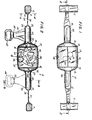
- Fig. 1 is a top plan view of a toy exercising arrangement of the present invention as mounted on two upper side rails of a crib or a similar enclosure in a use condition;.
- Fig. 2 is a longitudinal sectional view of the toy exercising arrangement in its use position, taken on line 2 - 2 of Fig. 1;
- Fig. 3 is a partially sectioned end view of the toy exercising arrangement, the section being taken on line 3 - 3 of Fig. 2; and
- Fig. 4 is an enlarged, partially sectioned, view of a detail of the toy exercising arrangement, the section being taken on line 4-4 of Fig. 2.
- Referring now to the drawing in detail, and first to Fig. 1 thereof, it may be seen that the
reference numeral 10 has been used therein to identify the exercising device according to the present invention in its entirety. The exercisingdevice 10 is soft and inflatable and constructed as a nursery toy that is useful for encouraging children, particularly infants, to develop their motor skills by performing exercise-type manual movements using thetoy 10 while playing with the same. The exercise device ornursery toy 10 is supported, while in use, across the upper region of an enclosure, such as a crib, of which only parts of two oppositeupper rails nursery toy 10 above the child and at least partially enclosing the area at which the child or infant is located while playing with thetoy 10. Non-limiting additional examples of such enclosures include a cradle and a playpen. - In its position of use, the
nursery toy 10 is substantially tautly suspended between therails exercise device 10 assumes a predetermined orientation or angular position about its main axis when it is intended that the child play with it in the most efficient way contemplated by the present invention. This currently preferred orientation of thenursery toy 10 is depicted in the drawing. - The
nursery toy 10 includes, as one of its main component parts, an air-inflatable, tubularcentral body 13 which is centered on, and elongated along, the aforementioned main axis of thetoy 10. Thecentral body 13 includes a substantially cylindricalcircumferential wall portion 14, and two substantially dome-shapedend wall portions circumferential wall portion 14 at opposite axial ends of the latter, byseams wall portions wall portions circumferential wall 14 is preferably transparent, while the material of theend wall portions circumferential wall portion 14 which is preferably clear. The circumfer--.ential wall portion 14 and theend wall portions - Two axially extending, air-inflatable, generally
tubular extensions central body 13 at opposite axial ends of the latter. Theextensions end wall portions central body 13 to form axial continuations of the same. Each of theextensions end wall portions extensions end wall portions end wall portions circumferential wall portion 14 of themain body 13 at theseams extensions end wall portions protective collars protective collars extensions - Each of the
extensions internal compartment internal compartments internal chamber 19 of thecentral body 13 via respective openings 26 and 27 provided substantially centrally, as shown in Fig. 2, in the respectiveend wall portions central body 13. Squeaker or similar air-operated noise-makingdevices 28 and 29 are arranged, and held in position, in the respective openings 26 and 27, in such a manner that most, and preferably all, of the air flow between thecompartments chamber 19 takes place through the respective one of them, with attendant noise generation. The construction of thedevices 28 and 29 is so known in the art of toy manufacture that it is deemed to be unnecessary to provide any description thereof herein. Suffice it to say that thedevices 28 and 29 may be of the well-known whistle type, or of the reed type. Any passage of air through thedevice 28 or 29 at a speed sufficient to activate thedevice 28 or 29, that is, to vibrate the reed, for instance, will result in generation of the corresponding sound or noise by thedevice 28 or 29. Of course, such forcible passage of air results from deformation of therespective extension central body 13, by external forces applied thereto by the child. - As mentioned before, the
nursery toy 10, that is thecentral body 13 and theextensions inflation valve 30 which again is of a well known construction not calling for explanation herein, and thus has only been diagrammatically indicated in Fig. 1 of the drawing. Theinflation valve 30 can be used for inflating thetoy 10 from its initial collapsed storage condition or configuration into its inflated condition or configuration of use. Then, thevalve 30 can be sealingly closed to keep the air introduced into the interior of thetoy 10 in thecompartments chamber 19. Yet, when it is desired to put thetoy 10 away for storage, thevalve 30 can also be used, after having been opened, to let the air escape from the interior of thetoy 10 and thus to deflate the latter into its collapsed configuration. - Toy objects 31, 32, and 33 are mounted and/or received in the
main chamber 19 of thecentral body 13 for at least limited movement relative to thecentral body 13. The toy objects 31, 32 and 33 are visible through the transparentcircumferential wall portion 14 of thecentral body 13. Thetoy object 31 is an animal-like mobile figure, which is suspended by aplastic strip 34 from the top of thecentral body 13, and is attached to the bottom of thecentral body 13 by anotherplastic strip 35. Thus, thetoy object 31 is capable of performing swinging movements to the extent permitted by the flexibility and dimensions of thestrips toy 10. The mobile figure constituting thetoy object 31 is preferably a three-dimensional figurine which is filled with foam and covered by sheet plastic material. However, preferably, the front-to-back dimension of thetoy object 31 is quite small, so that theobject 31 is basically flat. The toy objects 32 and 33 are balls received in thechamber 19 for unimpeded rolling movement therein. However, when any one of theballs flat object 31, it will cause the latter to conduct the aforementioned swinging motion. - As shown in Figs. 1 and 2, the
toy 10 is mounted on therails straps straps respective rail straps respective extensions straps respective extensions straps openings 38 each. Theseopenings 38 serve for adjustably connecting thetoy 10 to therails element 39 is provided for this purpose and includes acentral separating portion 40 and two bifurcated substantially T-shaped connectingportions openings 38 are shown to be elongated in the longitudinal direction of thestrap 36 and are so dimensioned that the connectingportions strap 36. On the other hand, when the connectingportions strap 36, as they do in the connecting orientation of the connectingelement 39, they contact the zones of the strap situated adjacent theopenings 38 and thus confine such zones between themselves and the separatingportion 40. In this manner, it is assured that the connectingelement 39 will not inadvertently or accidentally reorient itself and thus permit one or the other of the connectingportions respective opening 38. The connectingelements 39 are used in conjunction with such of theopenings 38 that the combination of thetoy 10 with thestraps straps toy 10 about the aforementioned main axis thereof. - To cause such rotation, elongated actuating
elements extensions regions extensions handles extensions - As shown particularly in Fig. 3, each of the
actuating elements respective extension toy 10 is mounted at the proper elevation. Also each of theactuating elements toy 10. Because of this, when the child pulls on one of the actuating straps 43 and 44, the wound portion of thisstrap extension extension entire toy 10, while an additional portion of theother strap other extension straps handles toy 10 will conduct turning motion about its main axis. - Of course, if so desired, the
toy 10 could also be suspended by means of thestraps extensions straps toy 10, but this could be useful for other purposes, for instance, to enable the infant to raise himself or herself into the sitting position. Thus, it may be seen that the purpose for which thetoy 10 is to be used largely determines the orientation in which it is mounted. - It-will be understood that each of the elements described above, or two or more together, may also find a useful application in other types of constructions differing from the types described above.
- While the invention has been illustrated and described as embodied in an inflatable overhead crib exercise toy, it is not to be limited to the details shown, since various modifications and structural changes may be made without departing in any way from the spirit of the present invention.
- Without further analysis, the foregoing will so fully reveal the gist of the present invention that others can, by applying current knowledge, readily adapt it for various applications without omitting features that, from the standpoint of prior art, fairly constitute essential characteristics of the generic or specific aspects of this invention and, therefore, such adaptations should and are intended to be comprehended within the meaning and range of equivalence of the following claims.
Claims (5)
1. An exercising arrangement, particularly for infants, to be mounted on spaced supporting structures, comprising an elongated body (13, 20, 21) centered on a main axis and having longitudinally spaced end portions; means, for mounting said body on the supporting structures for angular displacement about said main axis, including two mounting straps (36, 37) each secured to one of said end portions of said body (13, 20, 21) and detachably connected to one of the supporting structures in a use condition of the exercising arrangement in which one portion of said body is on top and another portion of said body is at the bottom of said body; and at least one elongated element (43; 44) connected to said body at a circumferential spacing from said other portion of said body in said use position and operative for turning said body about said main axis when pulled substantially downwardly.
2. An exercising arrangement, as claimed in claim 1, wherein said elongated element (43; 44) is flexible.
3. An exercising arrangement, as claimed in either of claims 1 and 2, further comprising an additional elongated element (43; 44) similar to said one elongated element and connected to said body (13) at substantially the same circumferential spacing from said other portion of said body as, but disposed in the opposite circumferential direction than, said one elongated element.
4. An exercising arrangement, as claimed in claim 3, .4. wherein said elongated body includes a central body section (13) of a larger diameter, and two extensions (20, 21) of a smaller diameter extending axially beyond said central body section to form continuations thereof; and wherein said one elongated element (43) is connected to one, and said additional elongated element (44) to the other, of said extensions (20,21).
5. An exercising arrangement, as claimed in any one of claims 1 to 4, wherein the or each said elongated element (43; 44) is an actuating strap.
Applications Claiming Priority (2)
| Application Number | Priority Date | Filing Date | Title |
|---|---|---|---|
| US56758084A | 1984-01-03 | 1984-01-03 | |
| US567580 | 1984-01-03 |
Publications (2)
| Publication Number | Publication Date |
|---|---|
| EP0149296A2 true EP0149296A2 (en) | 1985-07-24 |
| EP0149296A3 EP0149296A3 (en) | 1985-08-21 |
Family
ID=24267754
Family Applications (1)
| Application Number | Title | Priority Date | Filing Date |
|---|---|---|---|
| EP84301073A Withdrawn EP0149296A3 (en) | 1984-01-03 | 1984-02-20 | Exercising toy arrangement for infants |
Country Status (2)
| Country | Link |
|---|---|
| EP (1) | EP0149296A3 (en) |
| AU (1) | AU2463584A (en) |
Cited By (2)
| Publication number | Priority date | Publication date | Assignee | Title |
|---|---|---|---|---|
| US5057051A (en) * | 1990-11-29 | 1991-10-15 | Babicz Amy H | Night light toy apparatus |
| US5250002A (en) * | 1991-07-05 | 1993-10-05 | Benjamin Kinberg | Inflatable play gym |
Citations (4)
| Publication number | Priority date | Publication date | Assignee | Title |
|---|---|---|---|---|
| FR737336A (en) * | 1931-05-20 | 1932-12-09 | Gymnastics apparatus | |
| US4129961A (en) * | 1977-06-08 | 1978-12-19 | Parodi Arnold E | Spinning top and belt |
| FR2403088A1 (en) * | 1977-09-15 | 1979-04-13 | Dehan Charles | Gymnastic exerciser for back and chest muscles - has adjustable length elasticated strap with hand grips and hooks for fixing over door |
| US4335538A (en) * | 1980-11-12 | 1982-06-22 | Shelcore, Inc. | Inflatable overhead crib gym toy |
-
1984
- 1984-02-15 AU AU24635/84A patent/AU2463584A/en not_active Abandoned
- 1984-02-20 EP EP84301073A patent/EP0149296A3/en not_active Withdrawn
Patent Citations (4)
| Publication number | Priority date | Publication date | Assignee | Title |
|---|---|---|---|---|
| FR737336A (en) * | 1931-05-20 | 1932-12-09 | Gymnastics apparatus | |
| US4129961A (en) * | 1977-06-08 | 1978-12-19 | Parodi Arnold E | Spinning top and belt |
| FR2403088A1 (en) * | 1977-09-15 | 1979-04-13 | Dehan Charles | Gymnastic exerciser for back and chest muscles - has adjustable length elasticated strap with hand grips and hooks for fixing over door |
| US4335538A (en) * | 1980-11-12 | 1982-06-22 | Shelcore, Inc. | Inflatable overhead crib gym toy |
Cited By (2)
| Publication number | Priority date | Publication date | Assignee | Title |
|---|---|---|---|---|
| US5057051A (en) * | 1990-11-29 | 1991-10-15 | Babicz Amy H | Night light toy apparatus |
| US5250002A (en) * | 1991-07-05 | 1993-10-05 | Benjamin Kinberg | Inflatable play gym |
Also Published As
| Publication number | Publication date |
|---|---|
| EP0149296A3 (en) | 1985-08-21 |
| AU2463584A (en) | 1985-07-11 |
Similar Documents
| Publication | Publication Date | Title |
|---|---|---|
| US4767419A (en) | Protective pad for crib rail | |
| EP0275718B1 (en) | Playpen and exercise structure | |
| US5135440A (en) | System of water toys which may be assembled in play groupings | |
| CN102665841B (en) | Toy attachment systems and methods | |
| US4335538A (en) | Inflatable overhead crib gym toy | |
| US5820441A (en) | Animated doll | |
| US5186675A (en) | Air vent toy | |
| US5895308A (en) | Sound-producing soft toy missile | |
| US7901339B2 (en) | Device and method for occupying a human subject with physical and mental activities | |
| CN108378621B (en) | Pneumatic cushion device | |
| US2562080A (en) | Buoyant sustaining seat | |
| US6322454B1 (en) | Inflatable recreational device | |
| US4133064A (en) | Inflatable child's pillow | |
| US4146938A (en) | Combination bathtub and bassinet structure | |
| US3459423A (en) | Torsion bar swing construction | |
| US5941750A (en) | Doll having magnetically actuated functions | |
| US4288071A (en) | Pneumatic seesaw apparatus | |
| EP0149296A2 (en) | Exercising toy arrangement for infants | |
| US4179842A (en) | Audible sound emitting toy | |
| US20070245491A1 (en) | Punishment Pad/Mat for Toddlers | |
| US20020102909A1 (en) | Cloth shape with pockets for objects | |
| US1558200A (en) | Aquatic doll | |
| GB2299268A (en) | Children's play enclosure with inflatable base and displaceable boundary | |
| US20080113583A1 (en) | Clothing receptacle | |
| WO1988004567A1 (en) | Stuffed toy having spiral-shaped appendages |
Legal Events
| Date | Code | Title | Description |
|---|---|---|---|
| PUAI | Public reference made under article 153(3) epc to a published international application that has entered the european phase |
Free format text: ORIGINAL CODE: 0009012 |
|
| PUAL | Search report despatched |
Free format text: ORIGINAL CODE: 0009013 |
|
| AK | Designated contracting states |
Designated state(s): AT BE CH DE FR GB IT LI LU NL SE |
|
| AK | Designated contracting states |
Designated state(s): AT BE CH DE FR GB IT LI LU NL SE |
|
| 17P | Request for examination filed |
Effective date: 19860120 |
|
| 17Q | First examination report despatched |
Effective date: 19870114 |
|
| STAA | Information on the status of an ep patent application or granted ep patent |
Free format text: STATUS: THE APPLICATION IS DEEMED TO BE WITHDRAWN |
|
| 18D | Application deemed to be withdrawn |
Effective date: 19870526 |
|
| RIN1 | Information on inventor provided before grant (corrected) |
Inventor name: STUBBMAN, ALBERT |