EP0148945B1 - Verschluss für strahlungsquelle von ausgedehnter oberfläche - Google Patents
Verschluss für strahlungsquelle von ausgedehnter oberfläche Download PDFInfo
- Publication number
- EP0148945B1 EP0148945B1 EP84903108A EP84903108A EP0148945B1 EP 0148945 B1 EP0148945 B1 EP 0148945B1 EP 84903108 A EP84903108 A EP 84903108A EP 84903108 A EP84903108 A EP 84903108A EP 0148945 B1 EP0148945 B1 EP 0148945B1
- Authority
- EP
- European Patent Office
- Prior art keywords
- shutter
- openings
- plate
- optical plate
- outer optical
- Prior art date
- Legal status (The legal status is an assumption and is not a legal conclusion. Google has not performed a legal analysis and makes no representation as to the accuracy of the status listed.)
- Expired
Links
Images

Classifications
-
- G—PHYSICS
- G02—OPTICS
- G02B—OPTICAL ELEMENTS, SYSTEMS OR APPARATUS
- G02B26/00—Optical devices or arrangements for the control of light using movable or deformable optical elements
- G02B26/02—Optical devices or arrangements for the control of light using movable or deformable optical elements for controlling the intensity of light
-
- F—MECHANICAL ENGINEERING; LIGHTING; HEATING; WEAPONS; BLASTING
- F21—LIGHTING
- F21V—FUNCTIONAL FEATURES OR DETAILS OF LIGHTING DEVICES OR SYSTEMS THEREOF; STRUCTURAL COMBINATIONS OF LIGHTING DEVICES WITH OTHER ARTICLES, NOT OTHERWISE PROVIDED FOR
- F21V11/00—Screens not covered by groups F21V1/00, F21V3/00, F21V7/00 or F21V9/00
- F21V11/08—Screens not covered by groups F21V1/00, F21V3/00, F21V7/00 or F21V9/00 using diaphragms containing one or more apertures
- F21V11/14—Screens not covered by groups F21V1/00, F21V3/00, F21V7/00 or F21V9/00 using diaphragms containing one or more apertures with many small apertures
-
- G—PHYSICS
- G02—OPTICS
- G02B—OPTICAL ELEMENTS, SYSTEMS OR APPARATUS
- G02B5/00—Optical elements other than lenses
- G02B5/005—Diaphragms
Definitions
- This invention is directed to a shutter for producing a pulsed output from a radiant source.
- the purpose of this invention is to provide a means for interrupting the radiation from a blackbody source with a minimum reduction in its apparent area when in the "on" state.
- the shutter is particularly useful for producing pulsed emission from a beacon so that its position can be determined.
- the total radiant output of a blackbody source is proportional to the source area, the surface emissivity and the forth power of its absolute temperature.
- Such radiant output can be used as a beacon.
- pulsing can be accomplished by turning off the radiant source.
- the achievable frequency is related to the thermal source and its thermal mass.
- US-A-1 801 010 describes an adjustable lamp shade constructed of opaque material having windows therein. Adjustable shutters are provided for the windows to vary the amount of light emerging from the lamp disposed within the shade.
- an optical plate has openings therethrough and a shutter plate adjacent thereto.
- the shutter plate has similar openings, and can be moved from a position where the openings are aligned and the sutter is open to a position wherein the openings are nonaligned and the shutter is closed.
- the openings in the optical plate are divergent and adjoining to maximize the area and limit the angular distribution of the beam beyond the shutter.
- a shutter/extended area radiant energy source combination wherein the shutter is provided for selectively passing and blocking the energy radiating from the source in a first direction, said shutter being positioned adjacent said source in the first direction, said shutter comprising:
- the total radiant output of a blackbody source is proportional to the source area, the surface emissivity and the forth power of the absolute temperature of the source.
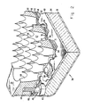
- a blackbody source such as the pyrotechnic device 34 of beacon 30 shown in FIG. 2
- this relationship must be modified to account for the shift in spectral distribution of the radiant energy in the desired bands. Increasing temperature causes a shift to shorter wavelength. Thus, the radiant output in a given wavelength band increases less than does the total output.
- FIG. 3 at the line 90 shows that the useful radiance is almost linear with temperature for the structure of this invention.
- the ordinate is the effective radiance in the 8 to 12 micrometer band in (watts-steradian-'-centimeter-2) x 10.
- Curve 92 shows the total radiance of the source in (watts-steradian-1-centimeter-2) x 10-', which varies as the fourth power of absolute temperature.
- Line 94 shows the perent of flux in the 8 to 12 micrometer band and shows the spectral efficiency drops with increasing temperature.
- Curve 90 is the product of curves 92 and 94.
- Curve 96 has as its ordinate the area in square inches for 10.8 watts .per steradian output. The required area drops with the temperaure increase.
- Curve 96 is the reciprocal of curve 90.
- the useful radiant power varies as T minus 700 degrees Kelvin while the total radiated power varies as T 4 (see line 92). Because of this substantial difference it is desirable to operate at as low a temperature as possible. In addition to energy efficiency, minimizing source temperature reduces problems with materials. In order to maximize the total radiant output, the blackbody
- the radiation source should be made as large as practical. In situations where the lateral area is limited by the size and/or shape of other structures, as in the case of the beacon 30 shown in FIG. 1, the source 30 takes an irregular shape in order to maximise its area. This irregular shape presents an additional constraint on the design of the shutter for interrupting the output radiation.
- the beacon 30 achieves the goal of maintaining maximum source area by using adjoining divergent surfaces which present reflections of the underlying blackbody 34 when the shutter is open, thus maintaining the effect of a full area emitter.
- FIG. 2 is an isometric view of beacon 30 with parts broken away on planes through the shutter openings.
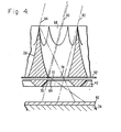
- FIG. 4 shows some of that structure in enlarged detail.
- Pyrotechnic device 34 preferably contains its own fuel and oxidizer and is exothermic when ignited.
- the pyrotechnic device 34 is contained in a forward housing 36 which extends rearwarly to embrace around outer plate 38 which serves as the main structural member of beacon 30. Housing 36 is closed by radiant source plate 40 which is heated by he pyrotechnic device 34 and radiates rearward, in the upward direction in FIG. 2, toward outer plate 38.
- Inner optical plate 42 is mounted to the forward side of outer optical plate 38 by a plurality of screws, one of which is shown at 44 in FIG. 2. Shoulder 45 on screw 44 engages against the forward face 46 of the outer optical plate 38 which is the main structural member of beacon 30. Head 47 on screw 44 is thus spaced from forward face 46. The shouldered shank of screw 44 engages through an opening in the inner optical plate 42 and head 47 serves to constrain the inner optical plate and prevent if from moving farther away from outer optical plate 38. There are several screws 44 adjacent the edges of plate 38, and in order to constrain the center portion of inner optical plate 42, rivets such as rivet 50 are appropriately spaced across the area of inner optical plate 42.
- Shutter 52 is a thin plate positioned against the forward surface 46 of outer optical plate 38.
- Shutter 52 has a slot adjacent all screws and rivets passing through the space 54 between the inner and outer optical plates. Such a slot is indicated at 56 with respect to rivet 50 in FIG. 2. At least three such screws or rivets are necessary to maintain the spacing and orientation of the optical plates.
- a slot is provided in the shutter 52 for all such screws and rivets, or they are positioned laterally of the periphery of shutter 52.
- the slots in shutter 52 around the screws and rivets are aligned in the same direction to permit sliding motion of the shutter plate preferably a distance slightly greater than the diameter of the radiating openings described below.
- shutter 52 is shown in an intermediate position between its left-most or closed and open positions.
- Spring 58 is a flat wave spring positioned in the pace 54 between inner optical plate 42 and shutter 52. Due to the curved nature of wave spring 58 in the unstressed condition, the wave spring urges shutter 52 rearward to lie against the forward surface 46 of outer optical plate 38.
- each of he elements at the rear of the beacon mechanism has an opening which is aligned with the openings in the other elements.
- a plurality of openings is provided, each being similar and spaced from each other, so only one such opening need be discussed.
- the cell openings 67 in the outer optical plate 38 are divergent in the direction of the radiant output and adjoin each other as hexagonal cells.
- One of the cell edges is shown at 69. This allows the perforated shutter plate 52 between the array of cells in outer optical plate 38 and the emitting source 40 to pass or block radiation by moving the shutter plate 52 by a distance equal to the diameter of the openings 72 in the shutter plate 52.
- the reflective cells are all the same so that only the cell 68 need be described in detail. It is formed with mirrored walls to maximize radiation.
- the cell walls can be formed of any of a variety of shapes as determined by the use and the method of fabrication.
- a truncted hexagonal pyramid is one appropriate cell shape.
- a truncated right circular cone may be more easily fabricated.
- Such compated cones are positioned so that the intersections form a hexagonal array. In addition, such a structure reduces multiple-reflection losses that occur in the corners of a hexagonal pyramid.
- a still more efficient shape is a truncated parabolic surface of revolution formed by a parabolic curve with the slope at the entrance and exit each chosen to provide a single reflection path to the source from any point in the angular field to be illuminated. This can be achieved for off-axis angles up to 20°.
- the lines 80, 82 and 84 in FIG. 4 indicate rays to an off-axis viewer. Throughout the intended field of view, the entire beacon area presents direct view or only single reflection of the source.
- the radiation source 40 is directly seen between lines 80 and 82 when the field of view is as far away from the line normal to the plane of the shutter as indicated in FIG. 4.
- the reflection of the source 40 is seen between lines 80 and 84, at the same angle.
- the lines 82 and 84 lie directly adjacent similar lines for adjacent view openings in the outer optical plate.
- the source is seen directly, or with a single reflection over the entire set of optical openings 68 in the outer optical plate within the angular limits at off-axis angles somewhat beyond that indicated by the lines 80, 82 and 84 in FIG. 4.
- the full area radiation is visible over a cone angle about the normal. The angle is a function of the size of the shutter depth of the outer optical plate 38 and the size of the reflective openings in the outer optical plate.
- the openings in the outer optical plate 38 are aligned with openings 71 in inner optical plate 42.
- Inner optical plate 42 provides mechanical constraint and heat shielding for the shutter 52.
- the wave spring 58 with its matching perforations holds the shutter plate in intimate contact with the forward face 46 of the main structural member 38 which is the outer optical plate to cause sharp cut-off. With the shutter held in place, radiation leakage is minimized. Furthermore, holding the shutter in place contrains the rise in shutter temperature by maintaining a thermal path to the larger mass of the main plate 38. It is important that the shutter and inner optical elements be shaped to avoid interference with the paths of radiation reflected by the outer optical array cell walls. The hole diameter and the shape of the divergent openings 68 achieve this purpose.
- all elements of the shutter have reflective, low absorptivity surfaces. Only the outer optical array surfaces are required to act as specular reflectors. The outer face of the shutter 52 must have low emissivity as it becomes the radiation source when the shutter is closed.
- the parabolic surface 68 intersects with forward surface 46 to define a ricular opening 70, which is preferably of slightly smaller diameter than the small end opening 64 of the truncated right circular cone 71 in inner optical plate 42.
- the openings 64 and 70 are in alignment.
- Opening 70 is the same size as or smaller than opening 72 in shutter 52.
- the shutter opening 72 is in alignment with circular opening 70 when the shutter 52 is in the open position as illustrated in FIG. 4.
- Beacon 30 is turned on an off by moving shutter 52 between the positions where the openings are in alignment and out of alignment. The direction of this shutter motion is controlled by the slots around the screws and rivets, for example, slot 56.
- the spacing between the openings 68 is such that the shutter 52 can be moved in the direction of the rightside section plane in FIG.
- the shutter can be operated by any desired actuator.
- An electromagnetic, pneumatic or hydraulic actuator can be selected for this operation. Because the required shutter motion is short even for a large area source, shutter actuation time can be on the order of a few milliseconds. Additonally, the shutter plate can be relatively thin to minimize the mass driven by the actuator
- the extended source shutter of this invention can be used for chopping or mudulation of various sources in the laboratory or in communication. Furthermore, in some applications it would be useful as an optical countermeasure source, and as an infrared signature simulator. In additon to the basic advantage of minimizing overall dimensions for a given output, the cellular nature of this shutter permits the shape and spatial variation of intensity of a laterally extended source to be substantially retained when viewed through the shutter.
- the outer optical array structure 38 can be built with internal passages for the circulation of coolant fluid so as to maintain shutter temperature sufficiently low to preserve the shutter and maintain a low radiant output in the off state.
Landscapes
- Physics & Mathematics (AREA)
- General Physics & Mathematics (AREA)
- Optics & Photonics (AREA)
- Engineering & Computer Science (AREA)
- General Engineering & Computer Science (AREA)
- Photometry And Measurement Of Optical Pulse Characteristics (AREA)
- Mechanical Light Control Or Optical Switches (AREA)
- Investigating Or Analysing Materials By Optical Means (AREA)
Claims (9)
- Kombination aus Verschluß/ausgedehnter Fläche-Strahlungsenergiequelle, worin der Verschluß zum selektiven Durchlassen und Abblokken der Strahlungsenergie von der Quelle in eine erste Richtung bereitgestellt wird, wobei der Verschluß en an die Quelle in der ersten Richtung angeordnet ist und der Verschluß aufweist:eine äußere optische Platte (38) mit einer Mehrzahl von Öffnungen (70) darin; undeine Verschlußplatte (52), welche zwischen der äußeren optischen Platte (38) und der Quelle (40) angeordnet ist, wobei die Verschlußplatte einer Mehrzahl von Öffnungen (72) durch sie hat, die Verschlußplatte beweglich angebracht ist, so daß in einer ersten Position der Verschlußplatte entsprechend der äußeren optischen Platte die Öffnungen in der Verschlußplatte und in der äußeren optischen Platte im wesentlichen ausgerichtet sind und in einer zweiten Position der Verschlußplatte bezüglich der äußeren optischen Platte die Öffnungen nicht ausgerichtet sind, um im wesentlichen die Übertragung von Strahlung von der Quelle durch den Verschluß abzublocken;dadurch gekennzeichnet, daß der Verschluß zusätzlich eine innere optische Platte (42) aufweist, welche eine Mehrzahl von Öffnungen (71) hat, die mit den Öffnungen in der äußeren optischen Platte ausgerichtet sind, wobei die innere optische Platte zwischen der Quelle und der Verschlußplatte angeordnet ist; unddaß die Öffnungen (70) in der äußeren Platte aneinandergrenzen und in der ersten Richtung divergent sind.
- 2. Kombination nach Anspruch 1, dadurch gekennzeichnet, daß die Öffnungen in der äußeren optischen Platte genügend eng zueinandersind, so daß die Wände von diesen Öffnungen sich miteinander schneiden.
- 3. Kombination nach Anspruch 2, dadurch gekennzeichnet, daß die Wände der Öffnungen sich in einem hexogonalen Muster miteinander schneiden.
- 4. Kombination nach Anspruch 2 oder 3, dadurch gekennzeichnet, daß die Wände der Öffnungen in der äußeren optischen Platte im wesentlichen die Form eines rechtwinkligen Kegelstumpfes mit kreisförmiger Grundfläche haben.
- 5. Kombination nach Anspruch 2 oder 3, dadurch gekennzeichnet, daß die Wände der divergenten Öffnungen in der äußeren optischen Platte im wesenlichen die Form eines rechtwinkligen Parabolstumpfes mit kreisförmiger Grundfläche haben.
- 6. Kombination nach einem der Ansprüche 1 bis 5, dadurch gekennzeichnet, daß die Wände der Öffnungen (79) in der inneren optischen Platte vom Nahbereich der Strahlungsquelle in Richtung der Verschlußplatte konvergieren.
- 7. Kombination nach Anspruch 6, dadurch gekennzeichnet, daß die Öffnungen in der inneren optischen Platte im wesentlichen die Oberflächen von Kegelstümpfen mit kreisförmiger Grundfläche sind.
- 8. Kombination nach einem der Ansprüche 1 bis 7, dadurch gekennzeichnet, daß die äußere optische Platte das Hapt-Strukturbauelement des Verschlusses ist.
- 9. Kombination nach Anspruch 1, dadurch gekennzeichnet, daß die äußere optiche Platte eine vorwärtige (46) und eine rückwärtige Oberfläche hat, zwischen denen sich die Mehrzahl der Öffnungen erstreckt wobei jede der Öffnungen einen Bereich einer parabolischen Drehoberfläche hat, welche in die erste Richtung divergiert und welche ausreichend nahe zueinander derart sind, daß sich Wände der dichtbenachbarten Öffnungen zwischen der vorwärtigen und rückwärtigen Oberfläche der äußeren optischen Platte miteinander schneiden und daß die Schnittform ein hexagonales Muster ist und die rückwärtige Apertur von den Öffnungen aus einer Gruppe von sechs bogenförmigen Ränderen besteht.
Applications Claiming Priority (2)
| Application Number | Priority Date | Filing Date | Title |
|---|---|---|---|
| US06/514,212 US4595258A (en) | 1983-07-06 | 1983-07-06 | Shutter for radiation source of extended area |
| US514212 | 1983-07-06 |
Publications (2)
| Publication Number | Publication Date |
|---|---|
| EP0148945A1 EP0148945A1 (de) | 1985-07-24 |
| EP0148945B1 true EP0148945B1 (de) | 1988-07-27 |
Family
ID=24046249
Family Applications (1)
| Application Number | Title | Priority Date | Filing Date |
|---|---|---|---|
| EP84903108A Expired EP0148945B1 (de) | 1983-07-06 | 1984-05-18 | Verschluss für strahlungsquelle von ausgedehnter oberfläche |
Country Status (9)
| Country | Link |
|---|---|
| US (1) | US4595258A (de) |
| EP (1) | EP0148945B1 (de) |
| JP (1) | JPS60501779A (de) |
| CA (1) | CA1227682A (de) |
| DE (1) | DE3473057D1 (de) |
| EG (1) | EG16673A (de) |
| IL (1) | IL72016A (de) |
| IT (1) | IT1179385B (de) |
| WO (1) | WO1985000434A1 (de) |
Families Citing this family (4)
| Publication number | Priority date | Publication date | Assignee | Title |
|---|---|---|---|---|
| DE3605226A1 (de) * | 1986-02-19 | 1987-08-27 | Daume & Jordan Gmbh & Co Kg | Blendungsfreie leuchte mit streifenfoermigem abblendreflektor |
| US5030837A (en) * | 1989-09-13 | 1991-07-09 | Hughes Aircraft Company | Thermal beacon assembly |
| FR2657147B1 (fr) * | 1990-01-17 | 1992-12-04 | Manade Sa | Dispositif d'eclairage, du type lampe de bureau, a ampoule fluorescente compacte. |
| US5870643A (en) * | 1995-12-28 | 1999-02-09 | Eastman Kodak Company | Single-use flash cameras with reflector or siren |
Family Cites Families (5)
| Publication number | Priority date | Publication date | Assignee | Title |
|---|---|---|---|---|
| US1801010A (en) * | 1930-02-17 | 1931-04-14 | Koenig Harry Mitchell | Adjustable-lamp shade |
| GB573900A (en) * | 1941-08-25 | 1945-12-12 | Harold Sefton Molyneux Ffennel | Improvements in or relating to signalling systems |
| JPS4940785A (de) * | 1972-08-22 | 1974-04-16 | ||
| GB1464001A (en) * | 1973-03-07 | 1977-02-09 | Buchert C | Data display panels |
| US3881810A (en) * | 1973-11-12 | 1975-05-06 | Sanders Associates Inc | Large field light modulator |
-
1983
- 1983-07-06 US US06/514,212 patent/US4595258A/en not_active Expired - Lifetime
-
1984
- 1984-05-18 EP EP84903108A patent/EP0148945B1/de not_active Expired
- 1984-05-18 DE DE8484903108T patent/DE3473057D1/de not_active Expired
- 1984-05-18 WO PCT/US1984/000764 patent/WO1985000434A1/en not_active Ceased
- 1984-05-18 JP JP84503103A patent/JPS60501779A/ja not_active Expired - Lifetime
- 1984-06-04 IL IL72016A patent/IL72016A/xx unknown
- 1984-07-04 IT IT48506/84A patent/IT1179385B/it active
- 1984-07-04 EG EG414/84A patent/EG16673A/xx active
- 1984-07-05 CA CA000458175A patent/CA1227682A/en not_active Expired
Also Published As
| Publication number | Publication date |
|---|---|
| JPS60501779A (ja) | 1985-10-17 |
| IT8448506A0 (it) | 1984-07-04 |
| WO1985000434A1 (en) | 1985-01-31 |
| CA1227682A (en) | 1987-10-06 |
| EP0148945A1 (de) | 1985-07-24 |
| IL72016A (en) | 1986-12-31 |
| DE3473057D1 (en) | 1988-09-01 |
| EG16673A (en) | 1993-02-28 |
| IT8448506A1 (it) | 1986-01-04 |
| US4595258A (en) | 1986-06-17 |
| IT1179385B (it) | 1987-09-16 |
Similar Documents
| Publication | Publication Date | Title |
|---|---|---|
| US6272269B1 (en) | Optical fiber/waveguide illumination system | |
| US5839823A (en) | Back-coupled illumination system with light recycling | |
| CA2113357C (en) | Non-imaging optical illumination system | |
| US5816693A (en) | Nonimaging optical illumination system | |
| US3322946A (en) | Reflector for reflecting color corrected light and heat | |
| EP0201013B1 (de) | Infrarot Projektoranordnung | |
| EP3369985B1 (de) | Leuchte mit lichtleiter | |
| EP1121837B1 (de) | Mikrowellenofen mit bräunungsgerät | |
| US4270844A (en) | Omni-directional compound paraboloid-hyperboloid radiation device | |
| HU210570B (en) | Treating lamp radiating polarized light | |
| JP2009523308A (ja) | 発光ダイオード用光学マニホールド | |
| AU767937B2 (en) | Solar energy receiver assembly | |
| JP2002175711A (ja) | 紫外線ランプシステム用反射器 | |
| IL128113A (en) | High-power, solid-state laser in a cylindrical package | |
| EP0148945B1 (de) | Verschluss für strahlungsquelle von ausgedehnter oberfläche | |
| GB2545017A (en) | A lighting device | |
| WO2016005423A1 (en) | Lighting device for coupling light from a light source into a light guide plate | |
| TW202210893A (zh) | 可調變光場範圍和具備高效能發射的通行感測器 | |
| CA3183339A1 (en) | Infrared heater | |
| RU2039343C1 (ru) | Тепловой излучатель | |
| JP3995687B2 (ja) | 誘電体レンズを用いた電磁波の反射器、発生器及び信号機 | |
| EP0206702A2 (de) | Tragbare Lampe mit einstellbarer Reflektorvorrichtung | |
| JP7144633B1 (ja) | Led照明装置 | |
| WO2005114265A1 (en) | Light flux transformer | |
| WO1996036197A1 (en) | Lightwave oven using highly reflective surface materials |
Legal Events
| Date | Code | Title | Description |
|---|---|---|---|
| PUAI | Public reference made under article 153(3) epc to a published international application that has entered the european phase |
Free format text: ORIGINAL CODE: 0009012 |
|
| 17P | Request for examination filed |
Effective date: 19850102 |
|
| AK | Designated contracting states |
Designated state(s): CH DE FR GB LI SE |
|
| RAP1 | Party data changed (applicant data changed or rights of an application transferred) |
Owner name: HUGHES AIRCRAFT COMPANY |
|
| 17Q | First examination report despatched |
Effective date: 19860919 |
|
| GRAA | (expected) grant |
Free format text: ORIGINAL CODE: 0009210 |
|
| AK | Designated contracting states |
Kind code of ref document: B1 Designated state(s): CH DE FR GB LI SE |
|
| REF | Corresponds to: |
Ref document number: 3473057 Country of ref document: DE Date of ref document: 19880901 |
|
| ET | Fr: translation filed | ||
| PLBE | No opposition filed within time limit |
Free format text: ORIGINAL CODE: 0009261 |
|
| STAA | Information on the status of an ep patent application or granted ep patent |
Free format text: STATUS: NO OPPOSITION FILED WITHIN TIME LIMIT |
|
| 26N | No opposition filed | ||
| EAL | Se: european patent in force in sweden |
Ref document number: 84903108.3 |
|
| REG | Reference to a national code |
Ref country code: GB Ref legal event code: 732E |
|
| REG | Reference to a national code |
Ref country code: GB Ref legal event code: IF02 |
|
| PGFP | Annual fee paid to national office [announced via postgrant information from national office to epo] |
Ref country code: FR Payment date: 20030411 Year of fee payment: 20 |
|
| PGFP | Annual fee paid to national office [announced via postgrant information from national office to epo] |
Ref country code: CH Payment date: 20030414 Year of fee payment: 20 |
|
| PGFP | Annual fee paid to national office [announced via postgrant information from national office to epo] |
Ref country code: SE Payment date: 20030417 Year of fee payment: 20 Ref country code: GB Payment date: 20030417 Year of fee payment: 20 |
|
| PGFP | Annual fee paid to national office [announced via postgrant information from national office to epo] |
Ref country code: DE Payment date: 20030428 Year of fee payment: 20 |
|
| PG25 | Lapsed in a contracting state [announced via postgrant information from national office to epo] |
Ref country code: LI Free format text: LAPSE BECAUSE OF EXPIRATION OF PROTECTION Effective date: 20040517 Ref country code: GB Free format text: LAPSE BECAUSE OF EXPIRATION OF PROTECTION Effective date: 20040517 Ref country code: CH Free format text: LAPSE BECAUSE OF EXPIRATION OF PROTECTION Effective date: 20040517 |
|
| REG | Reference to a national code |
Ref country code: GB Ref legal event code: PE20 |
|
| REG | Reference to a national code |
Ref country code: CH Ref legal event code: PL |
|
| EUG | Se: european patent has lapsed |