EP0148776B2 - Gusseisenbehälter - Google Patents
Gusseisenbehälter Download PDFInfo
- Publication number
- EP0148776B2 EP0148776B2 EP85300125A EP85300125A EP0148776B2 EP 0148776 B2 EP0148776 B2 EP 0148776B2 EP 85300125 A EP85300125 A EP 85300125A EP 85300125 A EP85300125 A EP 85300125A EP 0148776 B2 EP0148776 B2 EP 0148776B2
- Authority
- EP
- European Patent Office
- Prior art keywords
- nickel
- cast iron
- carbon
- welding
- insert
- Prior art date
- Legal status (The legal status is an assumption and is not a legal conclusion. Google has not performed a legal analysis and makes no representation as to the accuracy of the status listed.)
- Expired - Lifetime
Links
Images
Classifications
-
- G—PHYSICS
- G21—NUCLEAR PHYSICS; NUCLEAR ENGINEERING
- G21F—PROTECTION AGAINST X-RADIATION, GAMMA RADIATION, CORPUSCULAR RADIATION OR PARTICLE BOMBARDMENT; TREATING RADIOACTIVELY CONTAMINATED MATERIAL; DECONTAMINATION ARRANGEMENTS THEREFOR
- G21F1/00—Shielding characterised by the composition of the materials
- G21F1/02—Selection of uniform shielding materials
- G21F1/08—Metals; Alloys; Cermets, i.e. sintered mixtures of ceramics and metals
-
- B—PERFORMING OPERATIONS; TRANSPORTING
- B23—MACHINE TOOLS; METAL-WORKING NOT OTHERWISE PROVIDED FOR
- B23K—SOLDERING OR UNSOLDERING; WELDING; CLADDING OR PLATING BY SOLDERING OR WELDING; CUTTING BY APPLYING HEAT LOCALLY, e.g. FLAME CUTTING; WORKING BY LASER BEAM
- B23K35/00—Rods, electrodes, materials, or media, for use in soldering, welding, or cutting
- B23K35/001—Interlayers, transition pieces for metallurgical bonding of workpieces
- B23K35/004—Interlayers, transition pieces for metallurgical bonding of workpieces at least one of the workpieces being of a metal of the iron group
-
- B—PERFORMING OPERATIONS; TRANSPORTING
- B23—MACHINE TOOLS; METAL-WORKING NOT OTHERWISE PROVIDED FOR
- B23K—SOLDERING OR UNSOLDERING; WELDING; CLADDING OR PLATING BY SOLDERING OR WELDING; CUTTING BY APPLYING HEAT LOCALLY, e.g. FLAME CUTTING; WORKING BY LASER BEAM
- B23K9/00—Arc welding or cutting
- B23K9/02—Seam welding; Backing means; Inserts
- B23K9/0203—Inserts
-
- G—PHYSICS
- G21—NUCLEAR PHYSICS; NUCLEAR ENGINEERING
- G21F—PROTECTION AGAINST X-RADIATION, GAMMA RADIATION, CORPUSCULAR RADIATION OR PARTICLE BOMBARDMENT; TREATING RADIOACTIVELY CONTAMINATED MATERIAL; DECONTAMINATION ARRANGEMENTS THEREFOR
- G21F5/00—Transportable or portable shielded containers
- G21F5/06—Details of, or accessories to, the containers
- G21F5/12—Closures for containers; Sealing arrangements
Definitions
- This invention relates to cast iron containers and especially those for nuclear waste which are hermetically sealed by welding. It is more particularly concerned with those heavy walled, waste containers made from gray cast irons or ductile cast irons.
- nuclear waste containers to be geologically isolated, be designed to provide years of hermetic containment. Consequently, any design for such containers must address the problem of corrosion by geological fluids, as well as closure welding related failure concerns due to residual stresses in the weld metal and heat affected zones surrounding the fusion zone of the weld.
- a previously proposed concept for a waste container consisted of a heavy walled main body component casting of gray or ductile cast iron having a test tube like shape.
- the wall thickness of such containers in designs providing substantial radiation shielding of high-level waste can exceed 12 inches.
- After loading the nuclear waste material into the container casting the open end of the casting is hermetically sealed by welding a cast iron cylindrical plug into this opening.
- the plug has a depth on the order of the wall thickness of the container.
- the closure weld thus formed is tubular in shape, extending down around the circumference of the plug for a distance on the order of the wall thickness of the main body component.
- the phase structure of commercial gray and ductile Iron castings typically consists of ferrite and graphite at ambient temperature, but during welding the austenite phase will form in that region of the heat- affected zone nearest the fusion line. It is well known that if austenite is not slowly cooled it can transform into the strong non-equilibrium phase called martensite. Martensite is generally to be avoided in welded material since a volume increase accompanies it resulting in tensile stress in the adjacent material. This martensite related stress is likely to cause cracking in low ductility materials such as cast irons.
- the present invention resides in a container for nuclear waste as claimed in claim 1.
- the nickel-carbon alloy inserts are metallurgically bonded to the cast iron plug and cast iron main body and then welded to each other, thereby forming the hermetic seal around the radioactive contents to be stored.
- the fusion zone and the heat affected zone of this weld are contained substantially within the confines of the nickel carbon inserts, thereby preventing any adverse metallurgical effects in either the cast iron plug or cast iron main body component.
- the composition of the nickel-carbon alloy inserts is preferably selected such that their microstructures are characterized by islands of graphite phase in a matrix of nickel. It is desirable that the volume percentage of graphite phase in the nickel-carbon inserts minimizes any galvanic corrosion between the nickel-carbon inserts and the cast iron members they are bonded to.
- a convenient embodiment thereof elements interact to produce a simple eutectic system where the solid phases stable below 2404°F (1318°C) for compositions exceeding 0.55 weight percent carbon are nickel (containing small amounts of carbon in solid solution) and graphite.
- nickel-carbon welding inserts Although stress related to thermal and shrinkage effects would be greatly reduced by using a nickel-carbon welding insert, they cannot be totally eliminated and, therefore some accommodation must occur within the cast iron structure. However, with proper attention given to interrelated closure design and welding considerations it is possible to accommodate much of the stress by plastic deformation of the insert material.
- nuclear waste packages manufactured for geologic isolation should be designed to provide years of hermetic containment. Consequently, corrosion by geologic fluids as well as welding related considerations have to be addressed in any proposal involving use of dissimilar metals in waste package construction. The principal concern is that a galvanic corrosion condition may result whereby one of the metals will be attacked at an accelerated rate.
- the nickel-carbon alloy forming the insert will be more noble than the cast iron it is bonded to. While it is therefore believed that the cast iron will form the active material if coupled to nickel; i.e., the cast iron structure surrounding the nickel-rich closure welded insert on a nuclear waste package would selectively corrode galvanically in the presence of an electrolyte. This seemingly negative dissimilar metal condition would be partially nullified, however, by the low surface area ratio of the relatively noble nickel-rich insert to active cast iron.
- any concern over galvanic corrosion in the present invention is further reduced by considering the influence of the graphite phase in the nickel-carbon insert and cast iron materials.
- Graphite is a more noble material than either nickel or steel.
- the metallic portions of the cast iron and nickel-carbon weld insert should corrode preferentially to the particles of graphite contained within these materials.
- Typical cast irons contain from 3 to 4 weight percent (or from 11 to 15 volume percent) graphite, thus, similar composition nickel-carbon alloys are considered for the closure welding insert application.
- nickel-carbon alloys are used as bonded welding inserts to circumvent certain fundamental problems associated with direct welding of cast iron nuclear waste packages.
- a summary of the advantageous attributes of the container design and insert material are given below:
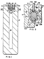
- a cylindrical heavy-wall nuc- tear waste container 1 is composed of two unassembled components, namely a main body component 10 and a plug component 100. Both components are mainly composed of cast iron, preferably grey or ductile cast iron, with sufficient wall thickness to provide the containment function with respect to any radioactive material to be held in cavity 20 of the main body component 10. At the opening to the cavity 20 a nickel carbon alloy insert or component 30 has been metallurgically bonded to the cast iron main body component 10. The bond interface is schematically shown at 32 and 34.
- a nickel-carbon alloy insert or component 200 has been metallurgically bonded to the circumferential periphery of the cast iron portion 300 of plug 100 forming a bond line interface 250.
- An insert-to-iron bonding method resulting in some fusion of the materials at their interfaces 32. 34 and 250, is selected to assure that all mechanical interfaces are hermetically sealed by metallurgical bonds.
- the nickel-carbon inserts 30 and 200 may be bonded to their respective components during the casting of the component by having the inserts preplaced in the casting mold.
- the inserts could be applied to the components as a thick weld overlay In any case.
- any adverse microstructural or stress conditions produced In the insert-to-cast iron bond region can be modified by controlling thermal conditions during the bonding operation or by subsequent heat treatment, prior to loading the main body component with nuclear waste material.
- closure of the assembled components involves joining the plug 100 and main body components 10 by welding the nickel carbon inserts 200 and 30 together using a suitable autogenous or filler metal welding process.
- a narrow groove. arc. filler metal welding process is illustrated in Fig. 2.
- the cast iron remains a stronger material since it is not subjected to severe elevated temperatures and, thus, is better able to react to those thermal and solidification strains transmitted from the insert welding operation without fracturing.
- Fig. 2 illustrates those thermal and solidification strains transmitted from the insert welding operation without fracturing.
- Fig. 2 shows the in-progress forming of the closure weld using a consumable welding electrode orfil- ler wire 2080 to fill the narrow tubular groove 2500 formed between inserts 30 and 200.
- groove 2500 will be completely filled with weld metal and fusion zone 1000 and heat affected zones 1030 and 1200 will extend to the top surfaces 36 and 280 of nickel carbon inserts 30 and 200, respectively.
- the weld rod 2080 may be selected from commercially available nickel-carbon, and nickel-carbon- iron alloy metal arc welding rods, and flux core wire.
- NI-ROD, NI-ROD 55, NI-ROD FC55 are suitable for use in the present invention.
- NI-ROD, a nickel-carbon welding electrode has a nominal composition of (wt.%): 95 Ni, 1.0 C, 0.2 Mn, 3.0 Fe, .005 S, 0.7 Si, and 0.1 Cu.
- NI-ROD is a preferred welding rod for use herein.
- joint design shown in the figures may require modification, since the closure welding process, joint design, and insert material thickness have to be developed together to insure that temperature and stress conditions produced in the surrounding cast iron fall below critical levels which can cause structural damage.
- the nickel-carbon inserts have a composition of from 2 to 5 weight percent carbon with the remainder of the alloy being nickel except for minor amounts of incidental impurities normally observed in commercially pure nickel (i.e. Nickel 200).
- the inserts which may be produced by casting, have a microstructure which is characterized by 8-20 volume percent of graphite, the actual volume percentage observed depends upon the carbon content of the alloy selected.
- the graphite is distributed in substantially isolated, or discontinuous, islands in a matrix structure which is essentially nickel containing small amounts of carbon in solution, in addition to any incidental impurities.
- the nickel-carbon binary, equilibrium phase diagram is eutectic in nature. Nickel does not undergo any solid state phase transformations. There are no stable nickel carbides. The two by the overall structure. This should eliminate any need for pre-weld or post-weld heat treatment.
Landscapes
- Engineering & Computer Science (AREA)
- Physics & Mathematics (AREA)
- General Engineering & Computer Science (AREA)
- High Energy & Nuclear Physics (AREA)
- Mechanical Engineering (AREA)
- Ceramic Engineering (AREA)
- Plasma & Fusion (AREA)
- Metallurgy (AREA)
- Arc Welding In General (AREA)
- Butt Welding And Welding Of Specific Article (AREA)
- Sealing Battery Cases Or Jackets (AREA)
- Packaging Of Annular Or Rod-Shaped Articles, Wearing Apparel, Cassettes, Or The Like (AREA)
- Refinement Of Pig-Iron, Manufacture Of Cast Iron, And Steel Manufacture Other Than In Revolving Furnaces (AREA)
Claims (4)
Applications Claiming Priority (2)
| Application Number | Priority Date | Filing Date | Title |
|---|---|---|---|
| US56907084A | 1984-01-09 | 1984-01-09 | |
| US569070 | 1984-01-09 |
Publications (3)
| Publication Number | Publication Date |
|---|---|
| EP0148776A1 EP0148776A1 (de) | 1985-07-17 |
| EP0148776B1 EP0148776B1 (de) | 1988-09-07 |
| EP0148776B2 true EP0148776B2 (de) | 1991-10-23 |
Family
ID=24273979
Family Applications (1)
| Application Number | Title | Priority Date | Filing Date |
|---|---|---|---|
| EP85300125A Expired - Lifetime EP0148776B2 (de) | 1984-01-09 | 1985-01-08 | Gusseisenbehälter |
Country Status (7)
| Country | Link |
|---|---|
| EP (1) | EP0148776B2 (de) |
| JP (1) | JPS60158399A (de) |
| KR (1) | KR850005715A (de) |
| CA (1) | CA1249456A (de) |
| DE (1) | DE3564880D1 (de) |
| ES (1) | ES8702074A1 (de) |
| PH (1) | PH24287A (de) |
Families Citing this family (3)
| Publication number | Priority date | Publication date | Assignee | Title |
|---|---|---|---|---|
| FR2841807B1 (fr) * | 2002-07-04 | 2004-09-17 | Technip France | Procede de fabrication d'un troncon d'une membrure d'une jambe de support d'une plate-forme d'exploitation en mer |
| EP2230043A1 (de) * | 2009-03-16 | 2010-09-22 | Siemens Aktiengesellschaft | Gussbauteil mit Schweissbrücke und Verfahren zum Herstellen des Gussbauteils |
| US10569939B1 (en) | 2016-03-21 | 2020-02-25 | United States Of America As Represented By The Administrator Of The National Aeronautics And Space Administration | Axially sealing plug |
Family Cites Families (5)
| Publication number | Priority date | Publication date | Assignee | Title |
|---|---|---|---|---|
| US3460237A (en) * | 1966-12-20 | 1969-08-12 | Westinghouse Electric Corp | Method of making a nuclear fuel element |
| US3838289A (en) * | 1972-08-29 | 1974-09-24 | Gilbert Associates | Radioactive waste filter removal system |
| FR2502379A1 (fr) * | 1981-03-20 | 1982-09-24 | Novatome Ind | Procede et dispositif de fermeture etanche amovible d'un conteneur pour combustible irradie |
| DE3149945A1 (de) * | 1981-12-17 | 1983-07-21 | Deutsche Gesellschaft für Wiederaufarbeitung von Kernbrennstoffen mbH, 3000 Hannover | Behaelter fuer die langzeitlagerung von abgebrannten kernreaktorbrennelementen |
| DE3214880A1 (de) * | 1982-04-22 | 1983-10-27 | Deutsche Gesellschaft für Wiederaufarbeitung von Kernbrennstoffen mbH, 3000 Hannover | Behaelter zur aufnahme von radioaktiven stoffen |
-
1984
- 1984-12-28 JP JP59282097A patent/JPS60158399A/ja active Pending
-
1985
- 1985-01-04 PH PH31682A patent/PH24287A/en unknown
- 1985-01-08 ES ES539412A patent/ES8702074A1/es not_active Expired
- 1985-01-08 DE DE8585300125T patent/DE3564880D1/de not_active Expired
- 1985-01-08 CA CA000471662A patent/CA1249456A/en not_active Expired
- 1985-01-08 EP EP85300125A patent/EP0148776B2/de not_active Expired - Lifetime
- 1985-01-09 KR KR1019850000077A patent/KR850005715A/ko not_active Ceased
Also Published As
| Publication number | Publication date |
|---|---|
| ES539412A0 (es) | 1986-12-01 |
| CA1249456A (en) | 1989-01-31 |
| KR850005715A (ko) | 1985-08-28 |
| ES8702074A1 (es) | 1986-12-01 |
| JPS60158399A (ja) | 1985-08-19 |
| DE3564880D1 (en) | 1988-10-13 |
| EP0148776A1 (de) | 1985-07-17 |
| PH24287A (en) | 1990-05-29 |
| EP0148776B1 (de) | 1988-09-07 |
Similar Documents
| Publication | Publication Date | Title |
|---|---|---|
| Gooch | Corrosion behavior of welded stainless steel | |
| Saluja et al. | The emphasis of phase transformations and alloying constituents on hot cracking susceptibility of type 304L and 316L stainless steel welds | |
| US4572959A (en) | Container for the interim and long-term storage of radioactive material | |
| CA2335894C (en) | Welding alloy and articles for use in welding, weldments and methods for producing weldments | |
| US4485961A (en) | Welding by hot isostatic pressing (HIP) | |
| US4213026A (en) | Age hardenable nickel superalloy welding wires containing manganese | |
| JPH0253158B2 (de) | ||
| US4700863A (en) | Seal welded cast iron nuclear waste container | |
| EP0148776B2 (de) | Gusseisenbehälter | |
| SE447034B (sv) | Brensleelementbehallare av gjutjern med kulgrafit for transport och/eller forvaring av bestralade kernreaktorbrensleelement | |
| US3948434A (en) | Extremely rapid and economical method for welding pipes, elongated reinforcing bars or the like in the field | |
| US6520432B2 (en) | Laser welding stainless steel components by stabilized ferritic stainless steel fusion zone modifiers | |
| JP6203868B2 (ja) | Fe−36Ni合金用の溶接ワイヤ | |
| Filippi et al. | Seal welded cast iron nuclear waste container | |
| JPS63157795A (ja) | 高張力鋼用ワイヤ | |
| US4558202A (en) | Weldment for austenitic stainless steel and method | |
| JPH02127981A (ja) | チタン合金の溶接方法 | |
| JP3042029B2 (ja) | 地層処分用複合容器 | |
| Lundberg | An evaluation of molybdenum and its alloys | |
| KIM AND JW MORRIS | The Development of a Ferritic Consumable for Welding Grain-Refined Fe-12Ni-0.25 Ti to Retain Toughness at 4.2 K | |
| Kumar | A Study on Behavior of Materials Under The Influence of Laser Joining | |
| Votinov et al. | Vanadium alloys as structural materials for fusion reactor blanket | |
| US3431102A (en) | Fusion welding filler metal with chromium nickel and vanadium alloying elements | |
| JPH0450108B2 (de) | ||
| JPH06691A (ja) | マグ溶接用フラックス入りワイヤ |
Legal Events
| Date | Code | Title | Description |
|---|---|---|---|
| PUAI | Public reference made under article 153(3) epc to a published international application that has entered the european phase |
Free format text: ORIGINAL CODE: 0009012 |
|
| AK | Designated contracting states |
Designated state(s): DE FR GB IT SE |
|
| 17P | Request for examination filed |
Effective date: 19860116 |
|
| 17Q | First examination report despatched |
Effective date: 19870525 |
|
| GRAA | (expected) grant |
Free format text: ORIGINAL CODE: 0009210 |
|
| AK | Designated contracting states |
Kind code of ref document: B1 Designated state(s): DE FR GB IT SE |
|
| REF | Corresponds to: |
Ref document number: 3564880 Country of ref document: DE Date of ref document: 19881013 |
|
| ET | Fr: translation filed | ||
| ITF | It: translation for a ep patent filed | ||
| PLBI | Opposition filed |
Free format text: ORIGINAL CODE: 0009260 |
|
| 26 | Opposition filed |
Opponent name: DEUTSCHE GESELLSCHAFT FUER WIEDERAUFBEREITUNG VON Effective date: 19890415 |
|
| PGFP | Annual fee paid to national office [announced via postgrant information from national office to epo] |
Ref country code: FR Payment date: 19901218 Year of fee payment: 7 |
|
| PGFP | Annual fee paid to national office [announced via postgrant information from national office to epo] |
Ref country code: GB Payment date: 19901220 Year of fee payment: 7 |
|
| PGFP | Annual fee paid to national office [announced via postgrant information from national office to epo] |
Ref country code: SE Payment date: 19901227 Year of fee payment: 7 |
|
| ITTA | It: last paid annual fee | ||
| PGFP | Annual fee paid to national office [announced via postgrant information from national office to epo] |
Ref country code: DE Payment date: 19910330 Year of fee payment: 7 |
|
| PUAH | Patent maintained in amended form |
Free format text: ORIGINAL CODE: 0009272 |
|
| STAA | Information on the status of an ep patent application or granted ep patent |
Free format text: STATUS: PATENT MAINTAINED AS AMENDED |
|
| 27A | Patent maintained in amended form |
Effective date: 19911023 |
|
| AK | Designated contracting states |
Kind code of ref document: B2 Designated state(s): DE FR GB IT SE |
|
| PG25 | Lapsed in a contracting state [announced via postgrant information from national office to epo] |
Ref country code: GB Effective date: 19920108 |
|
| PG25 | Lapsed in a contracting state [announced via postgrant information from national office to epo] |
Ref country code: SE Effective date: 19920109 |
|
| ET3 | Fr: translation filed ** decision concerning opposition | ||
| GBPC | Gb: european patent ceased through non-payment of renewal fee | ||
| PG25 | Lapsed in a contracting state [announced via postgrant information from national office to epo] |
Ref country code: FR Effective date: 19920930 |
|
| PG25 | Lapsed in a contracting state [announced via postgrant information from national office to epo] |
Ref country code: DE Effective date: 19921001 |
|
| REG | Reference to a national code |
Ref country code: FR Ref legal event code: ST |
|
| EUG | Se: european patent has lapsed |
Ref document number: 85300125.3 Effective date: 19920806 |