EP0147628B1 - Disposable capillary tube device - Google Patents
Disposable capillary tube device Download PDFInfo
- Publication number
- EP0147628B1 EP0147628B1 EP84114162A EP84114162A EP0147628B1 EP 0147628 B1 EP0147628 B1 EP 0147628B1 EP 84114162 A EP84114162 A EP 84114162A EP 84114162 A EP84114162 A EP 84114162A EP 0147628 B1 EP0147628 B1 EP 0147628B1
- Authority
- EP
- European Patent Office
- Prior art keywords
- plunger
- capillary tube
- tube
- support member
- hollow support
- Prior art date
- Legal status (The legal status is an assumption and is not a legal conclusion. Google has not performed a legal analysis and makes no representation as to the accuracy of the status listed.)
- Expired
Links
Images

Classifications
-
- B—PERFORMING OPERATIONS; TRANSPORTING
- B01—PHYSICAL OR CHEMICAL PROCESSES OR APPARATUS IN GENERAL
- B01L—CHEMICAL OR PHYSICAL LABORATORY APPARATUS FOR GENERAL USE
- B01L3/00—Containers or dishes for laboratory use, e.g. laboratory glassware; Droppers
- B01L3/02—Burettes; Pipettes
- B01L3/021—Pipettes, i.e. with only one conduit for withdrawing and redistributing liquids
- B01L3/0217—Pipettes, i.e. with only one conduit for withdrawing and redistributing liquids of the plunger pump type
- B01L3/022—Capillary pipettes, i.e. having very small bore
Definitions
- the invention relates to a disposable capillary tube device comprising a support member, a capillary tube mounted on the support member and having an outer end and an inner end with the outer end extending beyond the support member, and a plunger mounted on the support member substantially on the axis of the capillary tube and being axially movable.
- the support member of such a device consists of a ring with a holding portion, to which a rod of the piston is fixable.
- the piston is inserted in the capillary tube and is withdrawn to pick up liquid and advanced to discharge liquid.
- the presence of the piston in the capillary tube by liquid being drawn into the tube is a disadvantage when consistent accuracy is desired since it can cause the presence of an air bubble in the capillary tube. While this prior art recognizes the desirability of having such devices disposable, it still contemplates using operating parts to be removed from the disposable capillarytube and piston for re-use. This involves time-consuming operations.
- a similar device is known from the FR-A-2 319 117, the support member of which consists of a hollowtube, in which a stepped insert is slidably movable carrying a wire which is introduced into the capillary tube fixed to the hollow support over a predetermined length.
- the capillary tube In operation of the device, the capillary tube is contacted with the liquid to be picked up.
- the liquid fully fills the tube by capillary action.
- the air is free to pass out of the tube at the other end, as the plunger is withdrawn from the capillarytube and mounted in a predetermined distance therefrom.
- the device with the filled capillary tube can be moved to a desired point of discharge, where all the liquid contained in the capillary tube can be discharged by advancing the plunger to enter and move through the capillary tube.
- the plunger may consist of a wire, which is known per se.
- the end to be axially moved into the capillary tube is advantageously pointed.
- the support member is a card provided with slots on opposite sides for securing the capillary tube by a press fit and with a plurality of opposed raised bands integral with the card engaging opposite sides of the plunger and slidably holding the plunger on the axis of the capillarytube.
- the card consists usually of a plastic material, conveniently of a synthetic resin, for example a polyalkylene resin such as polyethylene or polypropylene, or a cellulose acetate butyrate, or cellulose acetate propionate.
- the support member is an elongated hollow support tube in which the inner end of the capillary tube is secured and in which the plunger is releasably mounted.
- the support tubes can be manufactured of a transparent material since this permits observing when the liquid being picked up has filled the capillarytube. Further, the entry of the plunger into the capillary tube can be viewed.
- the material of the support tubes is usually a thermoplastic material such as an acrylic resin, for example methyl methacrylate.
- the hollow support tube may have an extension portion which extends over a substantial portion of the capillary tube. Further, a cap can be press fit onto the free end of the hollow support tube extension portion.
- the plunger may have at least one bent wire portion engaging the inside of the hollow support tube, a reduced diameter portion frictionally engaging the plunger or a portion deviating from its axis which is retained by inwardly extending portions of the hollow support tube on either side of the first mentioned portion. Further, the plunger can be retained in position when not in use by a member removably attached to the exterior of the hollow support tube and to a portion of the plunger exterior of the hollow support tube.
- a preferred material for the support tube is polycarbonate resin or polystyrene.
- the capillary tube device 2 as shown in Figs. 1 to 4 comprises a card 4 provided with identical slots 8 and 10 in its right side 12 and with a similar slot 16 in its left side 18, in which a capillary tube 6 is secured by a press fit.
- the tube 6 is placed in the slots by sliding the tube axially into the slots.
- Card 4 has an opening 22 therethrough between slots 8 and 16 and an opening 24 therethrough between slots 10 and 16.
- the inner end 26 of tube 6 overlies an opening 28 in card 4 to permit viewing the tube 6 to see if it is full of liquid.
- the outer end 30 extends beyond card 4 to facilitate the picking up of a liquid.
- a wire piston 32 having a diameter to fit snugly inside capillary tube 6, is received in an opening 34 through card 4 and is retained by a pressed fit in slots 36 and 38 in the right side 12 of card 4 and in a similar slot 40 (Fig. 3) in the left side 18 of card 4 which has openings 44 and 46 therethrough which lie respectively between slots 38 and 40 and slots 36 and 40.
- Piston 32 is secured by a pressed fit in an opening 52 in piston rod 54.
- Piston rod 54 is slidably retained in card 4 by straps 56 and 58 integral with card 4 on one side of rod 48 and strap 60 integral with card 4 on the opposite side of rod 48. Straps 56, 58 and 60 keep the axis of piston rod 54 in alignment with the axis of capillary tube 6.
- Piston rod 54 has an enlarged end 64 to facilitate its manipulation.
- Piston 32 and piston rod 54 are mounted on card 4 by axially sliding them into the position shown in Fig. 1 where they are frictionally held in place until used.
- the device 2 In operation the device 2 is moved to bring end 30 of capillary tube 6 into contact with the liquid to be picked up. The liquid fully fills tube 6 by capillary action, air being free to pass out of tube 6.
- the capillary tube 6 is selected to provide the precise amount of liquid to be picked up. Since the wire piston 32 is withdrawn from the capillary tube 6, there is positive assurance that no air bubbles will be formed in capillary tube 6, thus insuring the accuracy of the amount of liquid picked up.
- the device 2 is then moved to a position with the capillary tube 6 at the desired point of discharge at which time piston rod 54 is advanced causing wire piston 32 to enter capillary tube 6 and move through the capillary tube to discharge all of the contained liquid.
- An alternative capillary tube device 70 (Fig. 5) is identical with device 2 except piston 74 is plastic and integral with plastic piston rod 72.
- a disposable capillary tube device 90 in accordance with the invention has a transparent support tube 92 having a forward end 94 and a rear end 96.
- a capillary tube 98 has its inner end 100 retained inside the outer end 94 of retaining tube 92 by a pressed fit.
- a wire plunger 104 has a pointed forward end 106 to facilitate entry into capillary tube 98.
- the pointed end 106 is spaced away from the capillary tube 98.
- Plunger 104 has a bent rear portion 108 forming a handle exterior of support tube 92.
- plunger 104 has opposed bent portions 112 and 114 frictionally engaging the inner wall 116 of support tube 92 to hold plunger 104 in support tube 92 and spaced away from capillary tube 98 until it is desired to advance the plunger 104 into capillary tube 98 to expel liquid picked up by the capillary tube.
- the outer diameter of the wire from which plunger 104 is formed is smaller than the inner diameter of support tube 92 in order to permit the passage of air through support tube 92 when capillary tube 98 is picking up a liquid.
- the inner wall 116 of support tube 92 is funneled in the area indicated at 120 to facilitate the entry of plunger 104 into capillary tube 98 which is also facilitated by pointed end 106.
- Fig. 7 shows the device of Fig. 6 modified by providing a support tube 92A which is identical with support tube 92 with the exception of having an extended forward reduced diameter portion 94A which holds capillary tube 98 by a pressed fit and extends over most (advantageously over 80%) of the capillary tube 98 leaving only a small portion projecting for the pickup of liquid.
- the portion 94A provides protection against breakage of capillary tube 98.
- the thus modified device of Fig. 6 is the preferred embodiment of the invention.
- a modified device 110 in accordance with the invention is shown in Fig. 8.
- the device 110 is the same as the device of Fig. 6 with the exceptions that plunger 104B does not have the bent portions 112 and 114 found in plunger 104 and support tube 92B has its rear end 96B formed into a reduced diameter portion to engage plunger 104B with sufficient friction to retain it in support tube 92B spaced from capillary tube 98 until it is desired to advance it through the capillary tube.
- FIG. 10 An alternative device 120 in accordance with the invention is shown in Fig. 10.
- the device 120 is identical with the device of Fig. 6 except it employs a modified plunger 104C which eliminates the bent portions 112 and 114 of plunger 104 and the support tube 92C of the device 120 differs from the support tube 92 of the device of Fig. 6 in having three inwardly extending bosses 122, 124 and 126 spaced apart 120° and engaging plunger 104C with sufficient friction to hold it in mounting tube 92C spaced from capillary tube 98 until it is desired to advance the plunger to expel liquid from capillary tube 98.
- FIG. 12 An alternative device 130 in accordance with the invention shown in Fig. 12 is the same as the device of Fig. 6 with the exceptions that a plunger 104D has a single bent portion 132 retained between a flattened portion 134 (Fig. 13) of retaining tube 92D which also has an inwardly extending boss 136 on one side of bent wire portion 132 and inwardly extending boss 138 on the other side of bent wire portion 132.
- the bosses retain the plunger 104D in mounting tube 92D spaced from capillary tube 98 until it is desired to advance the plunger 104D through the capillary tube 98 at which time the user urges plunger 104D towards capillary tube 98 which causes bent portion 132 to engage boss 136 and be deformed sufficiently to permit the bent portion 132 to pass beyond boss 136 as shown in Fig. 14.
- the flattened portion 134 of tube 92D prevents the rotation of the bent portion 132 and hence keeps it in alignment with the bosses 136 and 138.
- a device 140 in accordance with the invention is shown in Fig. 15.
- Device 140 is the same as the device shown in Fig. 6 with the exception that the plunger 104E does not have the bent portions 112 and 114 of plunger 104 and plunger 104E is held in its preoperating position by means of a piece of tape 142 adhesively secured to the end 96E of mounting tube 92E and to plunger 104E by an adhesive (not shown).
- the plunger 104E can be separated from tape 142 either by simply advancing the plunger towards the capillary tube 98 or by removal of the tape 142 from support tube 92E and plunger 104E.
- Fig. 16 discloses capillary tube device of Fig. 7 with a synthetic plastic cap 144 being a tapered inner diameter which forms a press fit with the free end of support tube 92A to further protect the pickup end of capillary tube 98 before use.
- the cap 144 is first removed from support tube reduced diameter portion 94A.
Landscapes
- Health & Medical Sciences (AREA)
- Clinical Laboratory Science (AREA)
- Chemical & Material Sciences (AREA)
- Chemical Kinetics & Catalysis (AREA)
- Devices For Use In Laboratory Experiments (AREA)
- Sampling And Sample Adjustment (AREA)
- External Artificial Organs (AREA)
- Media Introduction/Drainage Providing Device (AREA)
Description
- The invention relates to a disposable capillary tube device comprising a support member, a capillary tube mounted on the support member and having an outer end and an inner end with the outer end extending beyond the support member, and a plunger mounted on the support member substantially on the axis of the capillary tube and being axially movable.
- The support member of such a device, known from the US-A-3 828 987 and 3 720 354, consists of a ring with a holding portion, to which a rod of the piston is fixable. The piston is inserted in the capillary tube and is withdrawn to pick up liquid and advanced to discharge liquid. The presence of the piston in the capillary tube by liquid being drawn into the tube is a disadvantage when consistent accuracy is desired since it can cause the presence of an air bubble in the capillary tube. While this prior art recognizes the desirability of having such devices disposable, it still contemplates using operating parts to be removed from the disposable capillarytube and piston for re-use. This involves time-consuming operations.
- A similar device is known from the FR-A-2 319 117, the support member of which consists of a hollowtube, in which a stepped insert is slidably movable carrying a wire which is introduced into the capillary tube fixed to the hollow support over a predetermined length. With this device, there is also the risk of the inclusion of an air bubble in the liquid drawn into the capillary tube.
- It is the object of the invention to exclude presence of air bubbles in the liquid filling a capillary tube with a device of the generic kind.
- This object is obtained with the disposable capillary tube device of the generic kind, if a space for the passage of air out of the capillary tube as it picks up liquid is provided between the inner end of the capillary tube and the forward end of the plunger and if the plunger is positioned on the support member for axial movement into the capillary tube to expel liquid therefrom.
- In operation of the device, the capillary tube is contacted with the liquid to be picked up. The liquid fully fills the tube by capillary action. During this filling, the air is free to pass out of the tube at the other end, as the plunger is withdrawn from the capillarytube and mounted in a predetermined distance therefrom. As no air bubbles are included in the capillary tube, when it is filled, the accuracy of the amount of liquid picked up is ensured dependent on the selected capillary tube. The device with the filled capillary tube can be moved to a desired point of discharge, where all the liquid contained in the capillary tube can be discharged by advancing the plunger to enter and move through the capillary tube.
- The plunger may consist of a wire, which is known per se. The end to be axially moved into the capillary tube is advantageously pointed.
- In a preferred embodiment, the support member is a card provided with slots on opposite sides for securing the capillary tube by a press fit and with a plurality of opposed raised bands integral with the card engaging opposite sides of the plunger and slidably holding the plunger on the axis of the capillarytube. The card consists usually of a plastic material, conveniently of a synthetic resin, for example a polyalkylene resin such as polyethylene or polypropylene, or a cellulose acetate butyrate, or cellulose acetate propionate.
- In a further preferred embodiment the support member is an elongated hollow support tube in which the inner end of the capillary tube is secured and in which the plunger is releasably mounted. The support tubes can be manufactured of a transparent material since this permits observing when the liquid being picked up has filled the capillarytube. Further, the entry of the plunger into the capillary tube can be viewed. The material of the support tubes is usually a thermoplastic material such as an acrylic resin, for example methyl methacrylate.
- To protect the capillary tube from being broken, the hollow support tube may have an extension portion which extends over a substantial portion of the capillary tube. Further, a cap can be press fit onto the free end of the hollow support tube extension portion.
- For frictionally holding the plunger in place when not in use, the plunger may have at least one bent wire portion engaging the inside of the hollow support tube, a reduced diameter portion frictionally engaging the plunger or a portion deviating from its axis which is retained by inwardly extending portions of the hollow support tube on either side of the first mentioned portion. Further, the plunger can be retained in position when not in use by a member removably attached to the exterior of the hollow support tube and to a portion of the plunger exterior of the hollow support tube.
- If, as mentioned above, the tube diameter is to be reduced at a desired point, or if the tube is flattened or bosses are indented into the tube by simple deformation of the tube when it is in plastic state, a preferred material for the support tube is polycarbonate resin or polystyrene.
- Embodiments of the invention are explained by means of drawings, in which
- Fig. 1 is an elevational view of a first embodiment of a capillary tube device,
- Fig. 2 is the section 2-2 of Fig. 1,
- Fig. 3 is the section 3-3 of Fig. 1,
- Fig. 4 is the section 4-4 of Fig. 1,
- Fig. 5 shows in a view as Fig. 1 a modification of this embodiment in detail,
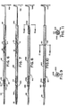
- Fig. 6 is a plan view partly broken away of a second embodiment of the device,
- Fig. 7 is a first modification of the device of Fig. 6 in the same view,
- Fig. 8 is a second modification of the device of Fig. 6 in the same view,
- Fig. 9 is the section 9-9 of Fig. 8,
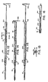
- Fig. 10 is a modification of Fig. 8 in the same view,
- Fig. 11 is the section 11-11 of Fig. 10,
- Fig. 12 is a third modification of the device of Fig. 6 in the same view,
- Fig. 13 is the section 13-13 of Fig. 12,
- Fig. 14 shows the device of Fig. 12 with the plunger advanced through the capillary tube,
- Fig. 15 is a second modification of the device of Fig. 8 in the same view, and
- Fig. 16 is a modification of the device of Fig. 7 in the same view.
- The
capillary tube device 2 as shown in Figs. 1 to 4 comprises acard 4 provided withidentical slots 8 and 10 in itsright side 12 and with asimilar slot 16 in itsleft side 18, in which acapillary tube 6 is secured by a press fit. Thetube 6 is placed in the slots by sliding the tube axially into the slots.Card 4 has an opening 22 therethrough betweenslots slots 10 and 16. Theinner end 26 oftube 6 overlies anopening 28 incard 4 to permit viewing thetube 6 to see if it is full of liquid. Theouter end 30 extends beyondcard 4 to facilitate the picking up of a liquid. - A
wire piston 32 having a diameter to fit snugly insidecapillary tube 6, is received in anopening 34 throughcard 4 and is retained by a pressed fit inslots right side 12 ofcard 4 and in a similar slot 40 (Fig. 3) in theleft side 18 ofcard 4 which hasopenings slots slots - Piston 32 is secured by a pressed fit in an opening 52 in
piston rod 54. Pistonrod 54 is slidably retained incard 4 bystraps card 4 on one side of rod 48 andstrap 60 integral withcard 4 on the opposite side of rod 48.Straps piston rod 54 in alignment with the axis ofcapillary tube 6. Pistonrod 54 has an enlargedend 64 to facilitate its manipulation. Piston 32 andpiston rod 54 are mounted oncard 4 by axially sliding them into the position shown in Fig. 1 where they are frictionally held in place until used. - In operation the
device 2 is moved to bringend 30 ofcapillary tube 6 into contact with the liquid to be picked up. The liquid fully fillstube 6 by capillary action, air being free to pass out oftube 6. Thecapillary tube 6 is selected to provide the precise amount of liquid to be picked up. Since thewire piston 32 is withdrawn from thecapillary tube 6, there is positive assurance that no air bubbles will be formed incapillary tube 6, thus insuring the accuracy of the amount of liquid picked up. Thedevice 2 is then moved to a position with thecapillary tube 6 at the desired point of discharge at whichtime piston rod 54 is advanced causingwire piston 32 to entercapillary tube 6 and move through the capillary tube to discharge all of the contained liquid. - An alternative capillary tube device 70 (Fig. 5) is identical with
device 2 exceptpiston 74 is plastic and integral withplastic piston rod 72. - Adverting to Fig. 6, a disposable capillary tube device 90 in accordance with the invention has a
transparent support tube 92 having aforward end 94 and arear end 96. Acapillary tube 98 has itsinner end 100 retained inside theouter end 94 ofretaining tube 92 by a pressed fit. - A
wire plunger 104 has a pointed forward end 106 to facilitate entry intocapillary tube 98. The pointed end 106 is spaced away from thecapillary tube 98.Plunger 104 has a bentrear portion 108 forming a handle exterior ofsupport tube 92. Intermediate end 106 and handle 108,plunger 104 has opposedbent portions inner wall 116 ofsupport tube 92 to holdplunger 104 insupport tube 92 and spaced away fromcapillary tube 98 until it is desired to advance theplunger 104 intocapillary tube 98 to expel liquid picked up by the capillary tube. The outer diameter of the wire from which plunger 104 is formed is smaller than the inner diameter ofsupport tube 92 in order to permit the passage of air throughsupport tube 92 whencapillary tube 98 is picking up a liquid. Theinner wall 116 ofsupport tube 92 is funneled in the area indicated at 120 to facilitate the entry ofplunger 104 intocapillary tube 98 which is also facilitated by pointed end 106. - Fig. 7 shows the device of Fig. 6 modified by providing a
support tube 92A which is identical withsupport tube 92 with the exception of having an extended forward reduceddiameter portion 94A which holdscapillary tube 98 by a pressed fit and extends over most (advantageously over 80%) of thecapillary tube 98 leaving only a small portion projecting for the pickup of liquid. Theportion 94A provides protection against breakage ofcapillary tube 98. The thus modified device of Fig. 6 is the preferred embodiment of the invention. - A modified
device 110 in accordance with the invention is shown in Fig. 8. Thedevice 110 is the same as the device of Fig. 6 with the exceptions that plunger 104B does not have thebent portions plunger 104 andsupport tube 92B has its rear end 96B formed into a reduced diameter portion to engageplunger 104B with sufficient friction to retain it insupport tube 92B spaced fromcapillary tube 98 until it is desired to advance it through the capillary tube. - An
alternative device 120 in accordance with the invention is shown in Fig. 10. Thedevice 120 is identical with the device of Fig. 6 except it employs a modifiedplunger 104C which eliminates thebent portions plunger 104 and thesupport tube 92C of thedevice 120 differs from thesupport tube 92 of the device of Fig. 6 in having three inwardly extendingbosses plunger 104C with sufficient friction to hold it in mountingtube 92C spaced fromcapillary tube 98 until it is desired to advance the plunger to expel liquid fromcapillary tube 98. - An
alternative device 130 in accordance with the invention shown in Fig. 12 is the same as the device of Fig. 6 with the exceptions that aplunger 104D has a singlebent portion 132 retained between a flattened portion 134 (Fig. 13) of retainingtube 92D which also has an inwardly extendingboss 136 on one side ofbent wire portion 132 and inwardly extendingboss 138 on the other side ofbent wire portion 132. The bosses retain theplunger 104D in mountingtube 92D spaced fromcapillary tube 98 until it is desired to advance theplunger 104D through thecapillary tube 98 at which time the user urgesplunger 104D towardscapillary tube 98 which causesbent portion 132 to engageboss 136 and be deformed sufficiently to permit thebent portion 132 to pass beyondboss 136 as shown in Fig. 14. The flattenedportion 134 oftube 92D prevents the rotation of thebent portion 132 and hence keeps it in alignment with thebosses - A
device 140 in accordance with the invention is shown in Fig. 15.Device 140 is the same as the device shown in Fig. 6 with the exception that theplunger 104E does not have thebent portions plunger 104 andplunger 104E is held in its preoperating position by means of a piece oftape 142 adhesively secured to theend 96E of mounting tube 92E and toplunger 104E by an adhesive (not shown). Theplunger 104E can be separated fromtape 142 either by simply advancing the plunger towards thecapillary tube 98 or by removal of thetape 142 from support tube 92E andplunger 104E. - Fig. 16 discloses capillary tube device of Fig. 7 with a synthetic
plastic cap 144 being a tapered inner diameter which forms a press fit with the free end ofsupport tube 92A to further protect the pickup end ofcapillary tube 98 before use. When used, of course, thecap 144 is first removed from support tube reduceddiameter portion 94A.
Claims (10)
Applications Claiming Priority (2)
| Application Number | Priority Date | Filing Date | Title |
|---|---|---|---|
| US06/568,350 US4662545A (en) | 1984-01-05 | 1984-01-05 | Disposable capillary tube device |
| US568350 | 1984-01-05 |
Publications (3)
| Publication Number | Publication Date |
|---|---|
| EP0147628A2 EP0147628A2 (en) | 1985-07-10 |
| EP0147628A3 EP0147628A3 (en) | 1987-02-04 |
| EP0147628B1 true EP0147628B1 (en) | 1989-05-31 |
Family
ID=24270918
Family Applications (1)
| Application Number | Title | Priority Date | Filing Date |
|---|---|---|---|
| EP84114162A Expired EP0147628B1 (en) | 1984-01-05 | 1984-11-23 | Disposable capillary tube device |
Country Status (5)
| Country | Link |
|---|---|
| US (1) | US4662545A (en) |
| EP (1) | EP0147628B1 (en) |
| JP (1) | JPS60222065A (en) |
| DE (1) | DE3478404D1 (en) |
| DK (1) | DK6485A (en) |
Families Citing this family (15)
| Publication number | Priority date | Publication date | Assignee | Title |
|---|---|---|---|---|
| US5059398A (en) * | 1985-07-22 | 1991-10-22 | Drummond Scientific Company | Disposable preselected-volume capillary pipet device |
| US4893738A (en) * | 1988-10-11 | 1990-01-16 | Loctite Corporation | Self-aligning positive displacement dispenser |
| US5454491A (en) * | 1993-08-30 | 1995-10-03 | World Precision Instruments, Inc. | Non-metallic precision fluid transfer devices |
| GB2283692A (en) * | 1993-11-11 | 1995-05-17 | Miles Atholl Blackwood Sewell | Dispensing device such as a pipette |
| US5440940A (en) * | 1994-03-18 | 1995-08-15 | Wilkins; Judd R. | Pipette-syringe-tubular microbial retrieval and sampler |
| US5616871A (en) * | 1995-09-28 | 1997-04-01 | Drummond Scientific Company | Pipet gun assembly |
| US5770158A (en) * | 1996-06-13 | 1998-06-23 | Diametrics Medical, Inc. | Capillary syringe |
| US6253628B1 (en) | 1998-08-21 | 2001-07-03 | Becton Dickinson And Company | Apparatus for drawing liquids into and expelling liquids from a pipet at variable flow rates |
| US6814936B1 (en) | 1999-07-01 | 2004-11-09 | Goran Enhorning | Pipette assembly having a small volume disposable tip |
| DE60012752T2 (en) * | 1999-08-17 | 2005-08-04 | The Technology Partnership Public Ltd. Co., Royston | FLEXIBLE PIPETTE STRIP AND RELATED APPLICATION METHOD |
| US7381371B2 (en) * | 2004-01-16 | 2008-06-03 | Heathrow Scientific Llc | Pipette device with pivotable nozzle assembly |
| USD510629S1 (en) | 2004-01-16 | 2005-10-11 | Heathrow Scientific Llc | Pipette device with pivotable nozzle assembly |
| US20090007701A1 (en) * | 2007-07-03 | 2009-01-08 | Hadjis Peter T | Pivoting pipette device |
| US20090010809A1 (en) * | 2007-07-03 | 2009-01-08 | Hadjis Peter T | Manual pipette filler |
| US20110046657A1 (en) * | 2009-08-20 | 2011-02-24 | Boston Scientific Scimed, Inc. | Embolic Coil Introducer Catheter Locking Mechanisms |
Family Cites Families (16)
| Publication number | Priority date | Publication date | Assignee | Title |
|---|---|---|---|---|
| CA836207A (en) * | 1970-03-10 | J. Denver William | Dip stick guide and wiper | |
| FR960103A (en) * | 1950-04-13 | |||
| US2254662A (en) * | 1940-12-13 | 1941-09-02 | Angelo F Naples | Oil gauge rod |
| US3153496A (en) * | 1961-11-20 | 1964-10-20 | Barber Colman Co | Syringe |
| US3401692A (en) * | 1964-06-26 | 1968-09-17 | Micro Tek Instr Corp | Syringe provided with a lateral vent and having high compression seals within the syringe bore |
| US3595090A (en) * | 1969-09-17 | 1971-07-27 | Drummond Instr Co | Apparatus for drawing fluid into, and discharging fluid from, a pipette |
| US3828987A (en) * | 1970-09-24 | 1974-08-13 | Drummond Instr Co | Dispensing micropipette apparatus having disposable parts for delivering a preselected quantity of fluid |
| US3720354A (en) * | 1970-09-24 | 1973-03-13 | Drummond Instr Co | Dispensing micropipette apparatus having disposable parts |
| US3677448A (en) * | 1971-01-29 | 1972-07-18 | Precision Sampling Corp | Syringe with wire plunger for dispensing infinitesimally small, accurately measured quantities of fluid |
| US3809298A (en) * | 1973-07-18 | 1974-05-07 | Precision Sampling Corp | Syringe |
| US4003262A (en) * | 1974-12-16 | 1977-01-18 | Becton, Dickinson And Company | Apparatus for measuring precise micro quantities of fluid samples |
| FR2319117A1 (en) * | 1975-07-25 | 1977-02-18 | Pasteur Institut | DEVICE FOR TAKING AND / OR DELIVERY OF LOW DOSE QUANTITIES OF LIQUID |
| US4050316A (en) * | 1975-11-03 | 1977-09-27 | Becton, Dickinson And Company | Pipette aspirator device |
| US4023716A (en) * | 1976-04-20 | 1977-05-17 | Justin Joel Shapiro | Micro-dispensing liquid pipet |
| US4063662A (en) * | 1976-07-08 | 1977-12-20 | Drummond Scientific Company | Calibrating means for a microdispenser |
| US4404862A (en) * | 1981-11-02 | 1983-09-20 | Dynatech Precision Sampling Corporation | Microdispensing springs with a needle in a tubular extension |
-
1984
- 1984-01-05 US US06/568,350 patent/US4662545A/en not_active Expired - Fee Related
- 1984-11-23 DE DE8484114162T patent/DE3478404D1/en not_active Expired
- 1984-11-23 EP EP84114162A patent/EP0147628B1/en not_active Expired
-
1985
- 1985-01-04 JP JP60000321A patent/JPS60222065A/en active Pending
- 1985-01-04 DK DK6485A patent/DK6485A/en not_active Application Discontinuation
Also Published As
| Publication number | Publication date |
|---|---|
| DE3478404D1 (en) | 1989-07-06 |
| US4662545A (en) | 1987-05-05 |
| JPS60222065A (en) | 1985-11-06 |
| DK6485D0 (en) | 1985-01-04 |
| EP0147628A3 (en) | 1987-02-04 |
| DK6485A (en) | 1985-07-06 |
| EP0147628A2 (en) | 1985-07-10 |
Similar Documents
| Publication | Publication Date | Title |
|---|---|---|
| EP0147628A2 (en) | Disposable capillary tube device | |
| US4270536A (en) | Disposable syringe | |
| JPS5931222Y2 (en) | biopsy specimen collector | |
| JP3821490B2 (en) | Skin pricker | |
| US20050119681A1 (en) | Lancets | |
| CA1290725C (en) | Equipment for measuring the erythrosettling rate of blood using pipettes | |
| EP0079498B1 (en) | Needle holding assembly | |
| DE3367854D1 (en) | Automatic injection device | |
| US4376590A (en) | Writing implement | |
| USD266338S (en) | Card holder and display device | |
| JP2003515420A (en) | Integrate capture and removal cap with lancet | |
| RO104499B1 (en) | Blood collecting device | |
| CA2269124A1 (en) | Method and apparatus for refillable stick dispenser | |
| AU745029B2 (en) | Safety vacuum syringe for blood sampling conformed to ergonomics | |
| EP0149721A2 (en) | Cigarette lighter holder/cigarette package clip | |
| US4875583A (en) | Needle cap replacement device | |
| US5213242A (en) | Storage device for an implanting tool | |
| USD257562S (en) | Identification label | |
| USD253270S (en) | Combined set of canisters and display holder therefor | |
| EP0086782B1 (en) | Package for fish baits with triple hooks | |
| EP0636501A1 (en) | Stick-shaped object dispenser | |
| ES2831362T3 (en) | Packaging for a prefilled drug delivery device | |
| KR100460303B1 (en) | needle for chinese medicine | |
| CA1104523A (en) | Writing implement | |
| US4184590A (en) | Coin holder and counter |
Legal Events
| Date | Code | Title | Description |
|---|---|---|---|
| PUAI | Public reference made under article 153(3) epc to a published international application that has entered the european phase |
Free format text: ORIGINAL CODE: 0009012 |
|
| AK | Designated contracting states |
Designated state(s): DE FR GB |
|
| PUAL | Search report despatched |
Free format text: ORIGINAL CODE: 0009013 |
|
| AK | Designated contracting states |
Kind code of ref document: A3 Designated state(s): DE FR GB |
|
| 17P | Request for examination filed |
Effective date: 19870218 |
|
| 17Q | First examination report despatched |
Effective date: 19871113 |
|
| GRAA | (expected) grant |
Free format text: ORIGINAL CODE: 0009210 |
|
| AK | Designated contracting states |
Kind code of ref document: B1 Designated state(s): DE FR GB |
|
| REF | Corresponds to: |
Ref document number: 3478404 Country of ref document: DE Date of ref document: 19890706 |
|
| ET | Fr: translation filed | ||
| PLBE | No opposition filed within time limit |
Free format text: ORIGINAL CODE: 0009261 |
|
| STAA | Information on the status of an ep patent application or granted ep patent |
Free format text: STATUS: NO OPPOSITION FILED WITHIN TIME LIMIT |
|
| 26N | No opposition filed | ||
| PGFP | Annual fee paid to national office [announced via postgrant information from national office to epo] |
Ref country code: FR Payment date: 19901129 Year of fee payment: 7 |
|
| PGFP | Annual fee paid to national office [announced via postgrant information from national office to epo] |
Ref country code: DE Payment date: 19910130 Year of fee payment: 7 |
|
| PGFP | Annual fee paid to national office [announced via postgrant information from national office to epo] |
Ref country code: GB Payment date: 19911105 Year of fee payment: 8 |
|
| PG25 | Lapsed in a contracting state [announced via postgrant information from national office to epo] |
Ref country code: FR Effective date: 19920731 |
|
| PG25 | Lapsed in a contracting state [announced via postgrant information from national office to epo] |
Ref country code: DE Effective date: 19920801 |
|
| REG | Reference to a national code |
Ref country code: FR Ref legal event code: ST |
|
| PG25 | Lapsed in a contracting state [announced via postgrant information from national office to epo] |
Ref country code: GB Effective date: 19921123 |
|
| GBPC | Gb: european patent ceased through non-payment of renewal fee |
Effective date: 19921123 |