EP0147575B1 - Drop-on-demand ink jet printers - Google Patents
Drop-on-demand ink jet printers Download PDFInfo
- Publication number
- EP0147575B1 EP0147575B1 EP84113326A EP84113326A EP0147575B1 EP 0147575 B1 EP0147575 B1 EP 0147575B1 EP 84113326 A EP84113326 A EP 84113326A EP 84113326 A EP84113326 A EP 84113326A EP 0147575 B1 EP0147575 B1 EP 0147575B1
- Authority
- EP
- European Patent Office
- Prior art keywords
- drop
- ink
- demand
- electrical drive
- ink jet
- Prior art date
- Legal status (The legal status is an assumption and is not a legal conclusion. Google has not performed a legal analysis and makes no representation as to the accuracy of the status listed.)
- Expired
Links
- 238000007639 printing Methods 0.000 claims description 20
- 238000004519 manufacturing process Methods 0.000 claims description 14
- 238000007641 inkjet printing Methods 0.000 claims description 13
- 230000004044 response Effects 0.000 claims description 9
- 238000004891 communication Methods 0.000 claims description 2
- 238000000034 method Methods 0.000 description 8
- 230000008569 process Effects 0.000 description 7
- 230000015572 biosynthetic process Effects 0.000 description 6
- 101100113692 Caenorhabditis elegans clk-2 gene Proteins 0.000 description 5
- 238000010586 diagram Methods 0.000 description 5
- 230000005499 meniscus Effects 0.000 description 4
- 238000013459 approach Methods 0.000 description 2
- 230000008859 change Effects 0.000 description 2
- 239000007788 liquid Substances 0.000 description 2
- 239000011159 matrix material Substances 0.000 description 2
- 230000003068 static effect Effects 0.000 description 2
- 230000001360 synchronised effect Effects 0.000 description 2
- 101100328957 Caenorhabditis elegans clk-1 gene Proteins 0.000 description 1
- 230000009471 action Effects 0.000 description 1
- 230000015556 catabolic process Effects 0.000 description 1
- 230000001143 conditioned effect Effects 0.000 description 1
- 238000006731 degradation reaction Methods 0.000 description 1
- 238000006073 displacement reaction Methods 0.000 description 1
- 230000000694 effects Effects 0.000 description 1
- 230000004886 head movement Effects 0.000 description 1
- 238000012545 processing Methods 0.000 description 1
- 230000002787 reinforcement Effects 0.000 description 1
- 238000012163 sequencing technique Methods 0.000 description 1
Images


Classifications
-
- B—PERFORMING OPERATIONS; TRANSPORTING
- B41—PRINTING; LINING MACHINES; TYPEWRITERS; STAMPS
- B41J—TYPEWRITERS; SELECTIVE PRINTING MECHANISMS, i.e. MECHANISMS PRINTING OTHERWISE THAN FROM A FORME; CORRECTION OF TYPOGRAPHICAL ERRORS
- B41J2/00—Typewriters or selective printing mechanisms characterised by the printing or marking process for which they are designed
- B41J2/005—Typewriters or selective printing mechanisms characterised by the printing or marking process for which they are designed characterised by bringing liquid or particles selectively into contact with a printing material
- B41J2/01—Ink jet
- B41J2/21—Ink jet for multi-colour printing
- B41J2/2121—Ink jet for multi-colour printing characterised by dot size, e.g. combinations of printed dots of different diameter
- B41J2/2128—Ink jet for multi-colour printing characterised by dot size, e.g. combinations of printed dots of different diameter by means of energy modulation
-
- B—PERFORMING OPERATIONS; TRANSPORTING
- B41—PRINTING; LINING MACHINES; TYPEWRITERS; STAMPS
- B41J—TYPEWRITERS; SELECTIVE PRINTING MECHANISMS, i.e. MECHANISMS PRINTING OTHERWISE THAN FROM A FORME; CORRECTION OF TYPOGRAPHICAL ERRORS
- B41J2202/00—Embodiments of or processes related to ink-jet or thermal heads
- B41J2202/01—Embodiments of or processes related to ink-jet heads
- B41J2202/06—Heads merging droplets coming from the same nozzle
Definitions
- This invention relates to ink jet printing apparatus and for generating ink drops on demand.
- Dot matrix printing at a resolution of 240 pels per inch produces printing that approaches the print quality produced by engraved type.
- a spot size of 125 to 150 mm is generally needed to give full area fill at a resolution of 240 pels per inch.
- a spot size of 125 to 150 mm requires that the nozzle diameter be of the order of 50 to 75 mm.
- transducer comprises a plurality of separately actuable sections.
- Control means is provided which is operable in response to the print data to selectively actuate a particular combination of one or more of the separately actuable sections of the transducer to produce an ink drop of one of a plurality of sizes as specified by the print data.
- a drop-on-demand ink jet printing apparatus comprising an ink jet print head having an ink cavity supplied with a suitable ink.
- An electromechanical transducer is mounted in mechanical communication with the ink cavity, and a source of electrical drive signals, repeatable at a predetermined drop-on-demand drop production rate, is provided to selectively actuate the electromechanical transducer to eject a single drop of ink having a predetermined size for each of the electrical drive signals.
- Means are also provided for selectively producing at least one additional electrical drive signal with a fixed time delay, relative to the immediately preceding electrical drive signal, and this fixed time delay is short with respect to the drop-on-demand drop production rate.
- the electromechanical transducer is also actuated with the additional electrical drive signals to eject an additional predetermined quantity of ink, with each of the quantities of ink merging into a single drop of ink prior to the time the drop reaches the print medium for printing so that each ink drop can be produced having a selected one of a plurality of possible drop sizes.
- the invention provides a drop-on-demand ink jet printing system comprising an ink jet head having an ink cavity, an orifice communicating with said ink cavity.
- the printer apparatus comprises a print head 10 to which is supplied liquid ink from ink supply means 12.
- Control means 14 provides the signals to control the printer apparatus including voltage control pulses to selectively energize print head 10 to produce one ink drop for each voltage pulse supplied to print head 10.
- print head 10 comprises a hollow cylindrical transducer member 16 closed at one end by a nozzle plate 18 to form a chamber or cavity 22 therein.
- Print head 10 could as well be any of the other impulse drop-on-demand heads known in the art.
- Cavity 22 is maintained filled with ink through supply line 24 from ink supply means 12. Ink from supply means 12 is not pressurized so the ink in cavity 22 is maintained at or near atmospheric pressure under static conditions.
- nozzle portion 20 An exit from cavity 22 is provided by nozzle portion 20 which is designed in conjunction with ink supply means 12 so that the ink does not flow out of, or air flow into, nozzle portion 20 under static conditions.
- Transducer 16 displaces radially when energized with a suitable voltage pulse, and produces a pressure wave in cavity 22 so that liquid ink is expelled out through nozzle portion 20 to form a single ink drop 26.
- Control means 14 provides the voltage drive pulses 60 (see FIG. 2) to selectively energize transducer 16 to produce one ink drop 26 for each suitable voltage pulse applied to transducer 16.
- print head 10 is traversed across the print medium at a substantially constant velocity and character bit data is generated by control means 14 in synchronism with the print head 10 movement.
- ink drops are produced by controlling the voltage drive to transducer 16.
- a selected voltage drive pulse 60 is produced (see FIG. 2) at each of the drop production times T for which an ink drop is required for printing, and no voltage drive pulse 60 is produced at intervals T in which no drop is required for printing. In this manner, drops can be formed at selected intervals T responsive to the character bit data to produce the desired print data on the print medium.
- the apparatus for providing the synchronized movement of print head 10 is known in the art, so that apparatus is not described here since detailed knowledge of that apparatus is not required for an understanding of the invention.
- printing apparatus which produces ink drops of selectively varying volume at constant velocity.
- the constant velocity is necessary since the print head 10 is moving at a constant velocity during printing and any variation in drop velocity would cause displacement from the desired print position which causes distortion and degradation of print quality.
- the different drop volumes available provide the option to operate the same printer in several different modes. For example, the drop volume can be selected to provide optimum full area fill to produce high resolution printing. On the other hand, by using only larger drops on a coarser matrix, a draft-mode print quality can be chosen.
- the printer would also be useful in any applications requiring halftone images, including control of color saturation hue and lightness.
- FIG. 9 is a print sample printed at a resolution of 240 pels per inch and at a drop-on-demand drop production rate of 5 KHz.
- the top three lines in FIG. 9 are printed with two voltage drive pulses 60 per pel. In the bottom three lines, the same data is printed with a single voltage drive pulse 60 per pel.
- This print sample shows the effect of a change in the drop size only as it affects the appearance of the printed text.
- a plurality of different size ink drops is produced by selectively providing a plurality of voltage drive pulses 60a-60n each spaced by a predetermined time which is small compared to the DOD drop production time T.
- a typical voltage drive pulse 60a having a selected amplitude and pulse width is shown which, when used to energize transducer 16, is operable to produce an ink drop 26 having one unit of volume.
- the voltage drive pulses are chosen to have a suitable amplitude and a pulse width which enhances the drop formation process.
- the voltage drive pulses preferably have a pulse width w determined by the relation Ua where L is the length of the ink cavity 22 and a is the velocity of sound in the ink.
- the predetermined delay time d between pulses is also chosen to enhance the drop formation process.
- the timing of 2Ua results in reinforcement of the original pulse reflection at the meniscus which amounts to a resonance mode operation for the embodiment shown.
- a timing d at or near resonance is preferred such as a timing chosen to be approximately 1.5 to 2 Ua.
- FIG. 5 is a sketch showing a series of high speed images at selected intervals in the drop formation process of the meniscus, and the ink that is ejected from the nozzle portion 20 in response to drive pulses 60a through 60d. A first volume of ink is ejected from the nozzle 20 in response to drive pulse 60a as can be seen in image 42-1.
- This volume of ink continues to move toward the print medium as is shown in image 42-2. It can be observed in image 42-3 that the second strong pressure wave produced in response to drive pulse 60b causes a second volume of ink to be ejected from nozzle 20. It can be observed in image 42-4 that the second volume of ink is ejected at a higher velocity due to the different boundary conditions, and for this reason it catches up with the first volume of ink and merges into a single drop of ink.
- the volume of the ink drop obtained in this way is approximately twice the volume of a single ink drop such as a drop formed by voltage drive pulse 60 alone. Should only two pulses 60a and 60b be present, then this size drop would continue until drop break-off occurs so that an ink drop having about two units of volume would be projected to the record medium for printing.
- images 42-5 and 42-6 show the third volume of ink ejected in response to drive pulse 60c
- images 42-7 and 42-8 show the fourth volume of ink ejected in response to drive pulse 60d.
- Image 42-9 shows the continuing flight of the four ink volumes
- image 42-0 shows that the four volumes of ink merge into one drop having 4 units of volume prior to break-off from the meniscus 44.
- FIG. 6 shows that each added voltage drive pulse 60 adds an approximately equal volume of ink to the resulting ink drop.
- Control means 14 may comprise any suitable means for accepting the data to be printed, which is usually in coded form, generating the bit patterns to produce the print data in the desired format, and producing the drive pulses to control transducer 16 to produce the desired print image on the record medium.
- Control means 14 may comprise hard wired logic circuits or this control may be provided by the processor of a data processing system of which the printer is a part.
- control means 14 may comprise a microcomputer which provides voltage drive pulses as well as other control functions for the printer. Other data sources, such as non-coded information data can also be printed.
- control means 14 shown comprises a storage device 30, a character generator 32, a clock pulse generator 34 and sequencing and control circuits 36.
- Storage device 30 functions to store the print data and the desired character fonts.
- Character generator 32 produces the appropriate bit pattern data and the drop size data which controls the size of each ink drop to be produced.
- Clock pulse generator 34 produces timing pulses to define cycles for storage device 30, character generator 32, and to synchronize other components of the system. These clock pulses may be derived from a system clock, if desired, and if so, the system clock pulses may be divided to produce pulses of the desired frequency.
- a pulse generator 38 is provided to generate signals CLK 1 to define the drop-on-demand production interval T.
- Pulse generator 38 receives as input a pulse train having a frequency proportional to the velocity of movement of print head 10 which is a substantially constant velocity during printing.
- the pulse train is usually generated by a position encoder associated with the moving print head as is known in the art.
- a second clock pulse source 40 is provided which produces pulses CLK 2 at a fixed frequency chosen to define the timing t between successive multiple voltage drive pulses.
- the clock pulses from source 40 may be derived from a system clock of from clock pulse generator 34, and, if so, the received clock pulses may be divided to produce the pulses CLK 2 of the desired frequency.
- the data to be printed is sent to storage device 30 on line 31, and this data is read out to character generator 32 over lines 33 when the data is to be printed as specified by signals from control circuits 36.
- Character generator 32 produces a data output on line 46, so that line 46 is at an up level when a dot is to be printed at a particular interval T or the line 46 is at a down level when no dot is to be printed.
- Character generator 32 also produces m bits of drop size data on line 48 which is coupled to control circuits 36. The m bits of drop size data are sufficient to specify n drop size levels, so in the case shown in FIGS. 4 and 5 for four drop size levels, two bits of drop size data are required.
- the pulse generator 38 receives the printer carriage encoder data on line 50 and produces an output comprising pulses which have a repetition rate equal to the drop production period T. These pulses are synchronized with the print head movement and these pulses are coupled to turn ON clock pulse generator 40 which produces output pulses CLK 2 at a repetition frequency equal to the chosen timing t to define the timing between successive multiple voltage drive pulses 60a-60n. In the specific embodiment illustrated in FIG. 4, this timing T would be chosen by 3 Ua. Each of the signals CLK 2 turns ON Single Shot Multivibrator 52 to produce an output pulse, the pulse width w of which is equal to the chosen width of the voltage drive pulses, and in the specific example of FIG. 4, this timing w is chosen as Ua.
- the output of Single Shot 52 therefore comprises a series of pulses having a pulse width defined by the Single Shot period and a repetition rate defined by the signal CLK 2.
- the output of Single Shot Multivibrator 52 is coupled to control circuits 36.
- the m size bits of data are decoded in control circuits 36 and a corresponding number n of pulses from Single Shot 52 are gated out on line 54 to provide one input to AND circuit 56.
- the data bit from character generator 32 provides the other input to AND circuit 32.
- driver 58 is energized with the n pulses to drive transducer 16 to produce a drop of ink having a size produced by n increments of volume. Should an array of transducers be used the circuit comprising AND circuit 46 and driver 58 would be included to control each transducer 16 in response to data from character generator 32 for specific transducer.
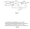
- FIG. 8 A specific example of the part of control circuits 14 which provide the decode and drive voltage pulse generation functions is shown in FIG. 8.
- the m bits of size data are coupled on line 48 to decoder 70.
- the m bits of data are decoded to produce a count n on lines 62.
- the count n is loaded broadside into counter 64 and the output of counter 64 is coupled to provide one input of AND circuit 66.
- the second input to AND circuit 66 is provided on line 68 from Single Shot Multivibrator 52. Each time an output pulse from single shot 52 is present, and a non-zero count is present in counter 64, AND circuit 66 is conditioned to produce an output pulse on line 54.
Landscapes
- Particle Formation And Scattering Control In Inkjet Printers (AREA)
Description
- This invention relates to ink jet printing apparatus and for generating ink drops on demand.
- There have been known in the prior art ink jet printing systems in which a transducer is selectively energized to produce ink drops on demand. Extensive efforts have been made to improve reliability and enhance the print quality and resolution of drop-on-demand ink jet printing systems.
- Dot matrix printing at a resolution of 240 pels per inch produces printing that approaches the print quality produced by engraved type. A spot size of 125 to 150 mm is generally needed to give full area fill at a resolution of 240 pels per inch. For most commercially available papers, a spot size of 125 to 150 mm requires that the nozzle diameter be of the order of 50 to 75 mm.
- Surface tension forces are indirectly proportional to the nozzle radius, so from this relationship it is apparent that a decrease in the nozzle dimension will increase the reliability of the drop generator as long as the nozzle does not clog. For most nozzle designs, the optimum reliability is obtained with nozzles having a diameter of the order of 30 to 50 mm. Thus, in general, in order to simultaneously optimize print quality and reliability, it is desirable to obtain the maximum drop volume using the smallest nozzle for which clogging does not occur. However, for printing systems which require high quality printing, it is recognized that, to obtain these desirable characteristics, incompatible requirements are presented.
- There have been attempts in prior art printing systems to produce larger than normal drops in the drop-on-demand mode from a nozzle of a particular size. One such system is disclosed in U.S. patent 3,946,398 in which the volume of ink in each drop is varied by adjusting the magnitude of the drive voltage pulse. Another system is disclosed in U.S. patent 4,281,331 to Tsuzuki et al in which the energy content of the transducer driving pulse determines the size of the ink drop.
- In some cases systems of the above-described type produce drops having a variation in drop velocity along with the change in drop size which degrades print quality. Compensation for this variation in velocity has been attempted in U.S. patent 4,222,060 to Sato et al by varying not only the amplitude but also the effective timing of each of the voltage drive pulses so that the resulting ink drops reach the print medium at the desired location. This compensation method requires complex control circuits which are difficult to modify to include future improvements.
- Another system is described in EP No. 101862, in which the transducer comprises a plurality of separately actuable sections. Control means is provided which is operable in response to the print data to selectively actuate a particular combination of one or more of the separately actuable sections of the transducer to produce an ink drop of one of a plurality of sizes as specified by the print data.
- It is therefore a principal object of this invention to provide an improved drop-on-demand printing system in which ink drops having selectively variable size are generated and utilized for printing.
- Briefly, according to the invention, there is provided a drop-on-demand ink jet printing apparatus comprising an ink jet print head having an ink cavity supplied with a suitable ink. An electromechanical transducer is mounted in mechanical communication with the ink cavity, and a source of electrical drive signals, repeatable at a predetermined drop-on-demand drop production rate, is provided to selectively actuate the electromechanical transducer to eject a single drop of ink having a predetermined size for each of the electrical drive signals. Means are also provided for selectively producing at least one additional electrical drive signal with a fixed time delay, relative to the immediately preceding electrical drive signal, and this fixed time delay is short with respect to the drop-on-demand drop production rate. The electromechanical transducer is also actuated with the additional electrical drive signals to eject an additional predetermined quantity of ink, with each of the quantities of ink merging into a single drop of ink prior to the time the drop reaches the print medium for printing so that each ink drop can be produced having a selected one of a plurality of possible drop sizes.
- Thus, the invention provides a drop-on-demand ink jet printing system comprising an ink jet head having an ink cavity, an orifice communicating with said ink cavity.
- The invention will now be further described with reference to the accompanying drawings, in which:
- FIG. 1 is a diagrammatic schematic view of a specific embodiment of the drop-on-demand ink jet printing system embodying the invention.
- FIG. 2 is a diagram showing the voltage drive pulses for operation of the drop-on-demand ink jet printing system of FIG. 1 having a single ink drop size.
- FIG. 3 is a diagram showing the voltage drive pulses for drop-on-demand operation of the drop-on-demand ink jet printing system of FIG. 1 in accordance with the present invention in which n ink drop sizes can be selectively produced.
- FIG. 4 is a diagram showing the voltage drive pulses for the specific embodiment of the present invention in which four drop sizes can be selectively produced.
- FIG. 5 is a sketch showing a series of high speed images, at selected intervals in the drop formation process, of the meniscus and the ink that is ejected from the nozzle in response to the voltage drive pulses shown in FIG. 4.
- FIG. 6 is a plot showing drop volume versus number n of
voltage drive pulses 60. - FIG. 7 is a schematic block diagram of one embodiment of the control means for controlling the printing system embodying the present invention.
- FIG. 8 is a schematic diagram of the part of the control means of FIG. 7 directed to selection of drop size in accordance with the present invention.
- FIG. 9 is a print sample printed in accordance with the invention at a resolution of 240 pels per inch and a drop-on-demand drop production rate of 5 KHz.
- Referring to FIG. 1, the printer apparatus comprises a
print head 10 to which is supplied liquid ink from ink supply means 12.Control means 14 provides the signals to control the printer apparatus including voltage control pulses to selectively energizeprint head 10 to produce one ink drop for each voltage pulse supplied to printhead 10. In the embodiment shown in the drawing,print head 10 comprises a hollowcylindrical transducer member 16 closed at one end by anozzle plate 18 to form a chamber orcavity 22 therein.Print head 10 could as well be any of the other impulse drop-on-demand heads known in the art.Cavity 22 is maintained filled with ink throughsupply line 24 from ink supply means 12. Ink fromsupply means 12 is not pressurized so the ink incavity 22 is maintained at or near atmospheric pressure under static conditions. An exit fromcavity 22 is provided bynozzle portion 20 which is designed in conjunction with ink supply means 12 so that the ink does not flow out of, or air flow into,nozzle portion 20 under static conditions. Transducer 16 displaces radially when energized with a suitable voltage pulse, and produces a pressure wave incavity 22 so that liquid ink is expelled out throughnozzle portion 20 to form asingle ink drop 26.Control means 14 provides the voltage drive pulses 60 (see FIG. 2) to selectively energizetransducer 16 to produce oneink drop 26 for each suitable voltage pulse applied totransducer 16. Although only one transducer is described it will be recognized by those skilled in the art than an array of transducers can be used, if desired. - During printing,
print head 10 is traversed across the print medium at a substantially constant velocity and character bit data is generated by control means 14 in synchronism with theprint head 10 movement. As is known in the art, in drop-on-demand (DOD) printing, ink drops are produced by controlling the voltage drive to transducer 16. A selectedvoltage drive pulse 60 is produced (see FIG. 2) at each of the drop production times T for which an ink drop is required for printing, and novoltage drive pulse 60 is produced at intervals T in which no drop is required for printing. In this manner, drops can be formed at selected intervals T responsive to the character bit data to produce the desired print data on the print medium. The apparatus for providing the synchronized movement ofprint head 10 is known in the art, so that apparatus is not described here since detailed knowledge of that apparatus is not required for an understanding of the invention. - According to the invention, printing apparatus is provided which produces ink drops of selectively varying volume at constant velocity. The constant velocity is necessary since the
print head 10 is moving at a constant velocity during printing and any variation in drop velocity would cause displacement from the desired print position which causes distortion and degradation of print quality. The different drop volumes available provide the option to operate the same printer in several different modes. For example, the drop volume can be selected to provide optimum full area fill to produce high resolution printing. On the other hand, by using only larger drops on a coarser matrix, a draft-mode print quality can be chosen. The printer would also be useful in any applications requiring halftone images, including control of color saturation hue and lightness. - One example of printing according to the invention is shown in FIG. 9. FIG. 9 is a print sample printed at a resolution of 240 pels per inch and at a drop-on-demand drop production rate of 5 KHz. The top three lines in FIG. 9 are printed with two
voltage drive pulses 60 per pel. In the bottom three lines, the same data is printed with a singlevoltage drive pulse 60 per pel. This print sample shows the effect of a change in the drop size only as it affects the appearance of the printed text. - Generally speaking, a plurality of different size ink drops is produced by selectively providing a plurality of voltage drive pulses 60a-60n each spaced by a predetermined time which is small compared to the DOD drop production time T. As shown in FIG. 3, a typical voltage drive pulse 60a having a selected amplitude and pulse width is shown which, when used to energize
transducer 16, is operable to produce anink drop 26 having one unit of volume. In addition, ink drops having further units of volume can be produced for any selected ink drop by having one or more subsequentvoltage drive pulses 60b-60n each of which follows the precedingvoltage drive pulse 60 by a predetermined delay time d. It is apparent that the pulse spacing T = pulse width w + delay time d. The voltage drive pulses are chosen to have a suitable amplitude and a pulse width which enhances the drop formation process. The voltage drive pulses preferably have a pulse width w determined by the relation Ua where L is the length of theink cavity 22 and a is the velocity of sound in the ink. The predetermined delay time d between pulses is also chosen to enhance the drop formation process. The timing of 2Ua results in reinforcement of the original pulse reflection at the meniscus which amounts to a resonance mode operation for the embodiment shown. A timing d at or near resonance is preferred such as a timing chosen to be approximately 1.5 to 2 Ua. - For this mode of operation, the drop formation process is substantially different from the process involved in the normal DOD drop formation process. This mode of operation can be understood by referring to FIGS. 4 and 5, in which four voltage drive pulses 60a-60d are selectively utilized to produce an ink drop. The voltage drive pulses 60a-60d are coupled to drive
transducer 16, and the resultant action can be observed by referring to FIG. 5. FIG. 5 is a sketch showing a series of high speed images at selected intervals in the drop formation process of the meniscus, and the ink that is ejected from thenozzle portion 20 in response to drive pulses 60a through 60d. A first volume of ink is ejected from thenozzle 20 in response to drive pulse 60a as can be seen in image 42-1. This volume of ink continues to move toward the print medium as is shown in image 42-2. It can be observed in image 42-3 that the second strong pressure wave produced in response to drivepulse 60b causes a second volume of ink to be ejected fromnozzle 20. It can be observed in image 42-4 that the second volume of ink is ejected at a higher velocity due to the different boundary conditions, and for this reason it catches up with the first volume of ink and merges into a single drop of ink. The volume of the ink drop obtained in this way is approximately twice the volume of a single ink drop such as a drop formed byvoltage drive pulse 60 alone. Should only twopulses 60a and 60b be present, then this size drop would continue until drop break-off occurs so that an ink drop having about two units of volume would be projected to the record medium for printing. - If additional voltage drive pulses of the same amplitude and pulse width are provided, the multiple wave cycles each produce unit volumes of ink which merge into a single drop of substantially larger volume. Continuing with the example shown in FIGS. 4 and 5, images 42-5 and 42-6 show the third volume of ink ejected in response to drive
pulse 60c, and images 42-7 and 42-8 show the fourth volume of ink ejected in response to drivepulse 60d. Image 42-9 shows the continuing flight of the four ink volumes and image 42-0 shows that the four volumes of ink merge into one drop having 4 units of volume prior to break-off from themeniscus 44. - This relationship is confirmed in the data shown in FIG. 6.
- FIG. 6 shows that each added
voltage drive pulse 60 adds an approximately equal volume of ink to the resulting ink drop. We have obtained drop volumes of up to 6 times that of the drop volume produced by a single voltage drive pulse, and there is no reason, in principle, why even higher values of n cannot be used. However it should be recognized that, for higher values of n, there is a tradeoff between drop size and drop-on-demand drop production rate since the successive increments of may approach the value T. In this case, to maintain reliable operation, it is necessary to increase the DOD drop production time T which reduces the DOD drop production rate. - Control means 14 may comprise any suitable means for accepting the data to be printed, which is usually in coded form, generating the bit patterns to produce the print data in the desired format, and producing the drive pulses to control
transducer 16 to produce the desired print image on the record medium. Control means 14 may comprise hard wired logic circuits or this control may be provided by the processor of a data processing system of which the printer is a part. In addition, control means 14 may comprise a microcomputer which provides voltage drive pulses as well as other control functions for the printer. Other data sources, such as non-coded information data can also be printed. - Referring to FIG. 7, the embodiment of control means 14 shown comprises a
storage device 30, acharacter generator 32, aclock pulse generator 34 and sequencing andcontrol circuits 36.Storage device 30 functions to store the print data and the desired character fonts.Character generator 32 produces the appropriate bit pattern data and the drop size data which controls the size of each ink drop to be produced.Clock pulse generator 34 produces timing pulses to define cycles forstorage device 30,character generator 32, and to synchronize other components of the system. These clock pulses may be derived from a system clock, if desired, and if so, the system clock pulses may be divided to produce pulses of the desired frequency. Apulse generator 38 is provided to generatesignals CLK 1 to define the drop-on-demand production intervalT. Pulse generator 38 receives as input a pulse train having a frequency proportional to the velocity of movement ofprint head 10 which is a substantially constant velocity during printing. The pulse train is usually generated by a position encoder associated with the moving print head as is known in the art. A secondclock pulse source 40 is provided which producespulses CLK 2 at a fixed frequency chosen to define the timing t between successive multiple voltage drive pulses. If desired, the clock pulses fromsource 40 may be derived from a system clock of fromclock pulse generator 34, and, if so, the received clock pulses may be divided to produce thepulses CLK 2 of the desired frequency. - In operation, the data to be printed is sent to
storage device 30 online 31, and this data is read out tocharacter generator 32 overlines 33 when the data is to be printed as specified by signals fromcontrol circuits 36.Character generator 32 produces a data output online 46, so thatline 46 is at an up level when a dot is to be printed at a particular interval T or theline 46 is at a down level when no dot is to be printed.Character generator 32 also produces m bits of drop size data online 48 which is coupled to controlcircuits 36. The m bits of drop size data are sufficient to specify n drop size levels, so in the case shown in FIGS. 4 and 5 for four drop size levels, two bits of drop size data are required. - The
pulse generator 38 receives the printer carriage encoder data online 50 and produces an output comprising pulses which have a repetition rate equal to the drop production period T. These pulses are synchronized with the print head movement and these pulses are coupled to turn ONclock pulse generator 40 which producesoutput pulses CLK 2 at a repetition frequency equal to the chosen timing t to define the timing between successive multiple voltage drive pulses 60a-60n. In the specific embodiment illustrated in FIG. 4, this timing T would be chosen by 3 Ua. Each of thesignals CLK 2 turns ONSingle Shot Multivibrator 52 to produce an output pulse, the pulse width w of which is equal to the chosen width of the voltage drive pulses, and in the specific example of FIG. 4, this timing w is chosen as Ua. - The output of
Single Shot 52 therefore comprises a series of pulses having a pulse width defined by the Single Shot period and a repetition rate defined by thesignal CLK 2. The output ofSingle Shot Multivibrator 52 is coupled to controlcircuits 36. The m size bits of data are decoded incontrol circuits 36 and a corresponding number n of pulses fromSingle Shot 52 are gated out online 54 to provide one input to ANDcircuit 56. The data bit fromcharacter generator 32 provides the other input to ANDcircuit 32. When the data indicates that a dot is to be printed during the current period T an up level is present online 46 so this up level is present during each of the pulses online 54 to condition ANDcircuit 56 during those pulses. Thereforedriver 58 is energized with the n pulses to drivetransducer 16 to produce a drop of ink having a size produced by n increments of volume. Should an array of transducers be used the circuit comprising ANDcircuit 46 anddriver 58 would be included to control eachtransducer 16 in response to data fromcharacter generator 32 for specific transducer. - A specific example of the part of
control circuits 14 which provide the decode and drive voltage pulse generation functions is shown in FIG. 8. The m bits of size data are coupled online 48 to decoder 70. The m bits of data are decoded to produce a count n on lines 62. The count n is loaded broadside intocounter 64 and the output ofcounter 64 is coupled to provide one input of ANDcircuit 66. The second input to ANDcircuit 66 is provided online 68 fromSingle Shot Multivibrator 52. Each time an output pulse fromsingle shot 52 is present, and a non-zero count is present incounter 64, ANDcircuit 66 is conditioned to produce an output pulse online 54. The output of ANDcircuit 66 is also coupled overline 72 through short delay 74 to decrement the count incounter 64 by one count. This operation continues until the count incounter 64 reaches zero at which time the output line ofcounter 64 goes down thereby deconditioning ANDcircuit 66. At the same time an output online 76 designates that a count = 0 is in the counter. The signal online 76 is utilized to setclock pulse generator 40 OFF. This operation results in n pulses being coupled to energizetransducer 16 which are spaced apart by a time period t which is short with respect to the drop production time T. - While the invention has been particularly shown and described with reference to a preferred embodiment thereof, it will be understood by those skilled in the art that various other changes in the form and details may be made therein without departing from the scope of the invention.
Claims (5)
Applications Claiming Priority (2)
| Application Number | Priority Date | Filing Date | Title |
|---|---|---|---|
| US06/562,302 US4513299A (en) | 1983-12-16 | 1983-12-16 | Spot size modulation using multiple pulse resonance drop ejection |
| US562302 | 1983-12-16 |
Publications (3)
| Publication Number | Publication Date |
|---|---|
| EP0147575A2 EP0147575A2 (en) | 1985-07-10 |
| EP0147575A3 EP0147575A3 (en) | 1986-03-12 |
| EP0147575B1 true EP0147575B1 (en) | 1988-03-09 |
Family
ID=24245705
Family Applications (1)
| Application Number | Title | Priority Date | Filing Date |
|---|---|---|---|
| EP84113326A Expired EP0147575B1 (en) | 1983-12-16 | 1984-11-06 | Drop-on-demand ink jet printers |
Country Status (5)
| Country | Link |
|---|---|
| US (1) | US4513299A (en) |
| EP (1) | EP0147575B1 (en) |
| JP (1) | JPS60157875A (en) |
| CA (1) | CA1204337A (en) |
| DE (1) | DE3469699D1 (en) |
Families Citing this family (76)
| Publication number | Priority date | Publication date | Assignee | Title |
|---|---|---|---|---|
| US5285215A (en) * | 1982-12-27 | 1994-02-08 | Exxon Research And Engineering Company | Ink jet apparatus and method of operation |
| US5202659A (en) * | 1984-04-16 | 1993-04-13 | Dataproducts, Corporation | Method and apparatus for selective multi-resonant operation of an ink jet controlling dot size |
| US4739415A (en) * | 1984-05-01 | 1988-04-19 | Canon Kabushiki Kaisha | Image handling system capable of varying the size of a recorded image |
| USRE37862E1 (en) | 1985-01-31 | 2002-10-01 | Thomas G. Hertz | Method and apparatus for high resolution ink jet printing |
| US4620196A (en) * | 1985-01-31 | 1986-10-28 | Carl H. Hertz | Method and apparatus for high resolution ink jet printing |
| CA1259853A (en) * | 1985-03-11 | 1989-09-26 | Lisa M. Schmidle | Multipulsing method for operating an ink jet apparatus for printing at high transport speeds |
| DE3620334A1 (en) * | 1985-06-21 | 1987-01-02 | Sharp Kk | PRINTING PROCESS |
| JPS63166545A (en) * | 1986-12-19 | 1988-07-09 | ゼロックス コーポレーション | Spot-size variable acoustic printer |
| DE3706468A1 (en) * | 1987-02-27 | 1988-09-08 | Siemens Ag | CHARACTER STORAGE METHOD AND ARRANGEMENT FOR REDUCING THE REDUNDANCY OF CHARACTERS FOR MATRIX PRINTERS WITH MULTIPASS PRINTING |
| US5252986A (en) * | 1987-05-20 | 1993-10-12 | Canon Kabushiki Kaisha | Image processing method for superposing plural dots on a recording medium at a predetermined interval and apparatus utilizing same |
| US5617123A (en) * | 1987-05-20 | 1997-04-01 | Canon Kabushiki Kaisha | Image processing method utilizing multiple binarizing and recording agent depositing steps |
| ATE116908T1 (en) * | 1989-10-10 | 1995-01-15 | Xaar Ltd | PRINTING PROCESS WITH MULTIPLE TONES. |
| US5512922A (en) * | 1989-10-10 | 1996-04-30 | Xaar Limited | Method of multi-tone printing |
| US5146236A (en) * | 1989-12-14 | 1992-09-08 | Ricoh Company, Ltd. | Ink jet record apparatus |
| JPH07125193A (en) * | 1989-12-15 | 1995-05-16 | Tektronix Inc | Drop on-demand type ink jet printing head and operating method thereof |
| US5170177A (en) * | 1989-12-15 | 1992-12-08 | Tektronix, Inc. | Method of operating an ink jet to achieve high print quality and high print rate |
| EP0437106B1 (en) * | 1990-01-08 | 1995-01-25 | Tektronix Inc. | Method and apparatus for printing with ink drops of varying sizes using a drop-on-demand ink jet print head |
| US5142307A (en) * | 1990-12-26 | 1992-08-25 | Xerox Corporation | Variable orifice capillary wave printer |
| US5521618A (en) * | 1991-08-16 | 1996-05-28 | Compaq Computer Corporation | Dual element switched digital drive system for an ink jet printhead |
| US5436648A (en) * | 1991-08-16 | 1995-07-25 | Compaq Computer Corporation | Switched digital drive system for an ink jet printhead |
| US5461403A (en) * | 1991-08-16 | 1995-10-24 | Compaq Computer Corporation | Droplet volume modulation techniques for ink jet printheads |
| DE69409020T2 (en) * | 1993-02-05 | 1998-07-02 | Hewlett Packard Co | System for reducing drive energy in a thermal inkjet high speed printer |
| US5557304A (en) * | 1993-05-10 | 1996-09-17 | Compaq Computer Corporation | Spot size modulatable ink jet printhead |
| US5444467A (en) * | 1993-05-10 | 1995-08-22 | Compaq Computer Corporation | Differential drive system for an ink jet printhead |
| US5426455A (en) * | 1993-05-10 | 1995-06-20 | Compaq Computer Corporation | Three element switched digital drive system for an ink jet printhead |
| US5689291A (en) * | 1993-07-30 | 1997-11-18 | Tektronix, Inc. | Method and apparatus for producing dot size modulated ink jet printing |
| US5495270A (en) * | 1993-07-30 | 1996-02-27 | Tektronix, Inc. | Method and apparatus for producing dot size modulated ink jet printing |
| US5764256A (en) * | 1994-03-03 | 1998-06-09 | Brother Kogyo Kabushiki Kaisha | System and method for ejecting ink droplets from a nozzle |
| US5969729A (en) * | 1994-05-27 | 1999-10-19 | Colorspan Corporation | Ink jet printer with artifact-reducing drive circuit |
| ATE183608T1 (en) | 1994-06-15 | 1999-09-15 | Compaq Computer Corp | METHOD AND PRINT HEAD FOR GENERATING GRADIENT TONE REPRESENTATIONS |
| US5513563A (en) * | 1994-11-14 | 1996-05-07 | Pitney Bowes Inc. | Indicia security via variable dot size |
| JPH08336970A (en) * | 1995-04-14 | 1996-12-24 | Seiko Epson Corp | Ink-jet type recording device |
| JPH0966603A (en) * | 1995-08-31 | 1997-03-11 | Brother Ind Ltd | Driving method for ink injector |
| US6065822A (en) * | 1996-04-16 | 2000-05-23 | Eastman Kodak Company | Printer capable of producing continuous tone prints from multi-bit data signals |
| JP2000516872A (en) * | 1996-08-27 | 2000-12-19 | トパーズ・テクノロジーズ・インコーポレイテッド | Inkjet printhead that produces variable volume ink drops |
| US5901425A (en) | 1996-08-27 | 1999-05-11 | Topaz Technologies Inc. | Inkjet print head apparatus |
| US6109732A (en) * | 1997-01-14 | 2000-08-29 | Eastman Kodak Company | Imaging apparatus and method adapted to control ink droplet volume and void formation |
| US6020905A (en) * | 1997-01-24 | 2000-02-01 | Lexmark International, Inc. | Ink jet printhead for drop size modulation |
| US6299288B1 (en) | 1997-02-21 | 2001-10-09 | Independent Ink, Inc. | Method and apparatus for variably controlling size of print head orifice and ink droplet |
| GB9802871D0 (en) * | 1998-02-12 | 1998-04-08 | Xaar Technology Ltd | Operation of droplet deposition apparatus |
| DE69808074T2 (en) * | 1997-05-15 | 2003-06-12 | Xaar Technology Ltd., Cambridge | OPERATION OF A DROPLET DEPOSITION DEVICE |
| US6352328B1 (en) | 1997-07-24 | 2002-03-05 | Eastman Kodak Company | Digital ink jet printing apparatus and method |
| US6375309B1 (en) | 1997-07-31 | 2002-04-23 | Canon Kabushiki Kaisha | Liquid discharge apparatus and method for sequentially driving multiple electrothermal converting members |
| US6102513A (en) * | 1997-09-11 | 2000-08-15 | Eastman Kodak Company | Ink jet printing apparatus and method using timing control of electronic waveforms for variable gray scale printing without artifacts |
| US6046822A (en) * | 1998-01-09 | 2000-04-04 | Eastman Kodak Company | Ink jet printing apparatus and method for improved accuracy of ink droplet placement |
| JP3475067B2 (en) * | 1998-02-02 | 2003-12-08 | 東芝テック株式会社 | Driving method of inkjet printer head |
| AU769733B2 (en) * | 1998-02-12 | 2004-02-05 | Xaar Technology Limited | Operation of droplet deposition apparatus |
| GB2338927B (en) * | 1998-07-02 | 2000-08-09 | Tokyo Electric Co Ltd | A driving method of an ink-jet head |
| GB2338928B (en) | 1998-07-02 | 2000-08-09 | Tokyo Electric Co Ltd | A driving method of an ink-jet head |
| US6390580B1 (en) * | 1999-04-27 | 2002-05-21 | Hewlett-Packard Company | Printhead registration apparatus and method |
| US6513894B1 (en) | 1999-11-19 | 2003-02-04 | Purdue Research Foundation | Method and apparatus for producing drops using a drop-on-demand dispenser |
| US6746100B2 (en) * | 2000-07-13 | 2004-06-08 | Brother Kogyo Kabushiki Kaisha | Ink jet recording apparatus and maintenance method |
| US6428135B1 (en) | 2000-10-05 | 2002-08-06 | Eastman Kodak Company | Electrical waveform for satellite suppression |
| US6561607B1 (en) | 2000-10-05 | 2003-05-13 | Eastman Kodak Company | Apparatus and method for maintaining a substantially constant closely spaced working distance between an inkjet printhead and a printing receiver |
| US6450602B1 (en) | 2000-10-05 | 2002-09-17 | Eastman Kodak Company | Electrical drive waveform for close drop formation |
| JP3920596B2 (en) | 2001-06-25 | 2007-05-30 | 東芝テック株式会社 | Inkjet recording apparatus and inkjet recording method |
| US20030016275A1 (en) * | 2001-07-20 | 2003-01-23 | Eastman Kodak Company | Continuous ink jet printhead with improved drop formation and apparatus using same |
| US6435666B1 (en) | 2001-10-12 | 2002-08-20 | Eastman Kodak Company | Thermal actuator drop-on-demand apparatus and method with reduced energy |
| US6460972B1 (en) | 2001-11-06 | 2002-10-08 | Eastman Kodak Company | Thermal actuator drop-on-demand apparatus and method for high frequency |
| US6601948B1 (en) | 2002-01-18 | 2003-08-05 | Illinois Tool Works, Inc. | Fluid ejecting device with drop volume modulation capabilities |
| JP3960083B2 (en) * | 2002-03-06 | 2007-08-15 | セイコーエプソン株式会社 | Head driving apparatus and method, liquid droplet ejection apparatus, head driving program, and device manufacturing method and device |
| US6896346B2 (en) * | 2002-12-26 | 2005-05-24 | Eastman Kodak Company | Thermo-mechanical actuator drop-on-demand apparatus and method with multiple drop volumes |
| US7700020B2 (en) * | 2003-01-09 | 2010-04-20 | Hewlett-Packard Development Company, L.P. | Methods for producing an object through solid freeform fabrication |
| US7281778B2 (en) | 2004-03-15 | 2007-10-16 | Fujifilm Dimatix, Inc. | High frequency droplet ejection device and method |
| US8491076B2 (en) * | 2004-03-15 | 2013-07-23 | Fujifilm Dimatix, Inc. | Fluid droplet ejection devices and methods |
| EP1616704A3 (en) * | 2004-07-16 | 2006-03-22 | Agfa-Gevaert | Method and apparatus to create a waiveform for driving a printhead |
| KR20070087223A (en) | 2004-12-30 | 2007-08-27 | 후지필름 디마틱스, 인크. | Ink jet printing |
| JP4815364B2 (en) * | 2006-05-24 | 2011-11-16 | 株式会社リコー | Liquid ejection apparatus and image forming apparatus |
| US7988247B2 (en) | 2007-01-11 | 2011-08-02 | Fujifilm Dimatix, Inc. | Ejection of drops having variable drop size from an ink jet printer |
| WO2009098871A1 (en) * | 2008-02-06 | 2009-08-13 | Panasonic Corporation | Method for manufacturing information recording medium |
| US8186790B2 (en) * | 2008-03-14 | 2012-05-29 | Purdue Research Foundation | Method for producing ultra-small drops |
| JP2010214894A (en) * | 2009-03-18 | 2010-09-30 | Toshiba Tec Corp | Inkjet head and nozzle plate |
| US8393702B2 (en) * | 2009-12-10 | 2013-03-12 | Fujifilm Corporation | Separation of drive pulses for fluid ejector |
| JP2013056523A (en) * | 2011-09-09 | 2013-03-28 | Mimaki Engineering Co Ltd | Printer head, inkjet printer, and printing method |
| PL3415316T3 (en) | 2017-06-13 | 2020-10-05 | Hymmen GmbH Maschinen- und Anlagenbau | Method and device for producing a structured surface |
| DE102019206431A1 (en) | 2019-05-03 | 2020-11-05 | Hymmen GmbH Maschinen- und Anlagenbau | Method for producing a structure on a surface |
Family Cites Families (14)
| Publication number | Priority date | Publication date | Assignee | Title |
|---|---|---|---|---|
| US3946398A (en) * | 1970-06-29 | 1976-03-23 | Silonics, Inc. | Method and apparatus for recording with writing fluids and drop projection means therefor |
| CH548866A (en) * | 1971-11-17 | 1974-05-15 | Battelle Memorial Institute | PRINTING DEVICE WITH LIQUID INK, CONDUCTING ELECTRICITY. |
| US3893131A (en) * | 1973-09-04 | 1975-07-01 | Xerox Corp | Ink printer |
| US3846800A (en) * | 1973-10-03 | 1974-11-05 | Ibm | Ink jet recording method and apparatus |
| GB1500908A (en) * | 1974-06-05 | 1978-02-15 | Ici Ltd | Process for production of drop streams |
| JPS5171630A (en) * | 1974-12-18 | 1976-06-21 | Matsushita Electric Ind Co Ltd | |
| US4047183A (en) * | 1976-11-04 | 1977-09-06 | International Business Machines Corporation | Method and apparatus for controlling the formation and shape of droplets in an ink jet stream |
| US4222060A (en) * | 1978-11-20 | 1980-09-09 | Ricoh Company, Ltd. | Ink jet printing apparatus |
| US4281333A (en) * | 1979-02-14 | 1981-07-28 | Nippon Electric Co., Ltd. | Ink-on-demand type ink-jet printer with coordinated variable size drops with variable charges |
| JPS55131882A (en) * | 1979-04-02 | 1980-10-14 | Canon Inc | Electronic equipment |
| US4353078A (en) * | 1979-09-24 | 1982-10-05 | International Business Machines Corporation | Ink jet print head having dynamic impedance adjustment |
| JPS57160654A (en) * | 1981-03-31 | 1982-10-04 | Fujitsu Ltd | Recording method in ink jet recording device |
| JPS57185159A (en) * | 1981-05-11 | 1982-11-15 | Nec Corp | Ink jet recorder |
| US4503444A (en) * | 1983-04-29 | 1985-03-05 | Hewlett-Packard Company | Method and apparatus for generating a gray scale with a high speed thermal ink jet printer |
-
1983
- 1983-12-16 US US06/562,302 patent/US4513299A/en not_active Expired - Fee Related
-
1984
- 1984-10-04 JP JP59207210A patent/JPS60157875A/en active Pending
- 1984-10-15 CA CA000465438A patent/CA1204337A/en not_active Expired
- 1984-11-06 DE DE8484113326T patent/DE3469699D1/en not_active Expired
- 1984-11-06 EP EP84113326A patent/EP0147575B1/en not_active Expired
Also Published As
| Publication number | Publication date |
|---|---|
| EP0147575A3 (en) | 1986-03-12 |
| EP0147575A2 (en) | 1985-07-10 |
| US4513299A (en) | 1985-04-23 |
| CA1204337A (en) | 1986-05-13 |
| DE3469699D1 (en) | 1988-04-14 |
| JPS60157875A (en) | 1985-08-19 |
Similar Documents
| Publication | Publication Date | Title |
|---|---|---|
| EP0147575B1 (en) | Drop-on-demand ink jet printers | |
| CA1143780A (en) | Voltage modulated drop-on-demand ink jet | |
| US5975667A (en) | Ink jet recording apparatus and method utilizing two-pulse driving | |
| US6305773B1 (en) | Apparatus and method for drop size modulated ink jet printing | |
| JP3552694B2 (en) | Ink jet recording device | |
| US5956056A (en) | Ink jet recording apparatus and method of recording with separated image data | |
| EP0105156B1 (en) | Ink jet printing apparatus and methods of operating such apparatus | |
| EP0670224B1 (en) | Multicolour printing apparatus | |
| JPH04250045A (en) | Drop on demand-type ink jet printer | |
| JP3667118B2 (en) | Recording apparatus and recording method | |
| EP1016524B1 (en) | Print head, printing apparatus and print head driving method | |
| EP1120256B1 (en) | Ink jet recording apparatus, method of controlling the apparatus, and recording medium having the method recorded thereon | |
| EP0799708B1 (en) | High speed print method and ink jet recording apparatus using the same | |
| US7384111B2 (en) | Liquid ejection apparatus and method of controlling the same | |
| JP2011088346A (en) | Liquid jet apparatus, and method for controlling liquid jet apparatus | |
| JP3552717B2 (en) | Ink jet recording device | |
| JP2004174849A (en) | Recording method of inkjet head | |
| JP2701249B2 (en) | Inkjet recording method | |
| JPS61293863A (en) | Tone expression of ink jet printing device | |
| JP3054189B2 (en) | Inkjet head drive system and recording apparatus | |
| JPH09141862A (en) | Ink-jet type printer apparatus | |
| JPH07329317A (en) | Continuous injection type ink jet recorder | |
| JP2002086764A (en) | Ink jet recording apparatus | |
| JPH09233288A (en) | Image recording device | |
| JPH05330084A (en) | Recording device |
Legal Events
| Date | Code | Title | Description |
|---|---|---|---|
| PUAI | Public reference made under article 153(3) epc to a published international application that has entered the european phase |
Free format text: ORIGINAL CODE: 0009012 |
|
| 17P | Request for examination filed |
Effective date: 19841214 |
|
| AK | Designated contracting states |
Designated state(s): DE FR GB IT |
|
| PUAL | Search report despatched |
Free format text: ORIGINAL CODE: 0009013 |
|
| AK | Designated contracting states |
Kind code of ref document: A3 Designated state(s): DE FR GB IT |
|
| 17Q | First examination report despatched |
Effective date: 19870521 |
|
| GRAA | (expected) grant |
Free format text: ORIGINAL CODE: 0009210 |
|
| AK | Designated contracting states |
Kind code of ref document: B1 Designated state(s): DE FR GB IT |
|
| REF | Corresponds to: |
Ref document number: 3469699 Country of ref document: DE Date of ref document: 19880414 |
|
| ET | Fr: translation filed | ||
| ITF | It: translation for a ep patent filed | ||
| PLBE | No opposition filed within time limit |
Free format text: ORIGINAL CODE: 0009261 |
|
| STAA | Information on the status of an ep patent application or granted ep patent |
Free format text: STATUS: NO OPPOSITION FILED WITHIN TIME LIMIT |
|
| 26N | No opposition filed | ||
| REG | Reference to a national code |
Ref country code: FR Ref legal event code: GC |
|
| REG | Reference to a national code |
Ref country code: GB Ref legal event code: 732 |
|
| REG | Reference to a national code |
Ref country code: FR Ref legal event code: TP |
|
| ITPR | It: changes in ownership of a european patent |
Owner name: CESSIONE;LEXMARK INTERNATIONAL INC. |
|
| ITPR | It: changes in ownership of a european patent |
Owner name: PEGNO;J.P. MORGAN DELAWARE |
|
| PGFP | Annual fee paid to national office [announced via postgrant information from national office to epo] |
Ref country code: FR Payment date: 19921021 Year of fee payment: 9 Ref country code: DE Payment date: 19921021 Year of fee payment: 9 |
|
| PGFP | Annual fee paid to national office [announced via postgrant information from national office to epo] |
Ref country code: GB Payment date: 19921030 Year of fee payment: 9 |
|
| ITTA | It: last paid annual fee | ||
| PG25 | Lapsed in a contracting state [announced via postgrant information from national office to epo] |
Ref country code: GB Effective date: 19931106 |
|
| GBPC | Gb: european patent ceased through non-payment of renewal fee |
Effective date: 19931106 |
|
| PG25 | Lapsed in a contracting state [announced via postgrant information from national office to epo] |
Ref country code: FR Effective date: 19940729 |
|
| PG25 | Lapsed in a contracting state [announced via postgrant information from national office to epo] |
Ref country code: DE Effective date: 19940802 |
|
| REG | Reference to a national code |
Ref country code: FR Ref legal event code: ST |