EP0147407B1 - Steam generator control systems - Google Patents
Steam generator control systems Download PDFInfo
- Publication number
- EP0147407B1 EP0147407B1 EP19840901679 EP84901679A EP0147407B1 EP 0147407 B1 EP0147407 B1 EP 0147407B1 EP 19840901679 EP19840901679 EP 19840901679 EP 84901679 A EP84901679 A EP 84901679A EP 0147407 B1 EP0147407 B1 EP 0147407B1
- Authority
- EP
- European Patent Office
- Prior art keywords
- flow
- boiler
- feedwater
- steam
- temperature
- Prior art date
- Legal status (The legal status is an assumption and is not a legal conclusion. Google has not performed a legal analysis and makes no representation as to the accuracy of the status listed.)
- Expired
Links
- 239000007789 gas Substances 0.000 claims abstract description 60
- 238000012937 correction Methods 0.000 claims abstract description 9
- XLYOFNOQVPJJNP-UHFFFAOYSA-N water Substances O XLYOFNOQVPJJNP-UHFFFAOYSA-N 0.000 claims description 18
- 238000012546 transfer Methods 0.000 claims description 7
- 238000013461 design Methods 0.000 claims description 5
- 238000011144 upstream manufacturing Methods 0.000 claims description 2
- 230000008016 vaporization Effects 0.000 claims description 2
- 238000009834 vaporization Methods 0.000 claims description 2
- 230000009977 dual effect Effects 0.000 abstract description 10
- 238000013459 approach Methods 0.000 description 7
- 229920006395 saturated elastomer Polymers 0.000 description 7
- 239000003570 air Substances 0.000 description 5
- 238000004364 calculation method Methods 0.000 description 5
- 230000001276 controlling effect Effects 0.000 description 5
- 230000001105 regulatory effect Effects 0.000 description 5
- QVGXLLKOCUKJST-UHFFFAOYSA-N atomic oxygen Chemical compound [O] QVGXLLKOCUKJST-UHFFFAOYSA-N 0.000 description 3
- 239000001301 oxygen Substances 0.000 description 3
- 229910052760 oxygen Inorganic materials 0.000 description 3
- 230000007797 corrosion Effects 0.000 description 2
- 238000005260 corrosion Methods 0.000 description 2
- 230000000694 effects Effects 0.000 description 2
- 239000012530 fluid Substances 0.000 description 2
- 238000012423 maintenance Methods 0.000 description 2
- 239000000463 material Substances 0.000 description 2
- 238000011084 recovery Methods 0.000 description 2
- 239000007787 solid Substances 0.000 description 2
- 239000000956 alloy Substances 0.000 description 1
- 229910045601 alloy Inorganic materials 0.000 description 1
- 239000012080 ambient air Substances 0.000 description 1
- 230000000712 assembly Effects 0.000 description 1
- 238000000429 assembly Methods 0.000 description 1
- BIJOYKCOMBZXAE-UHFFFAOYSA-N chromium iron nickel Chemical compound [Cr].[Fe].[Ni] BIJOYKCOMBZXAE-UHFFFAOYSA-N 0.000 description 1
- 238000010276 construction Methods 0.000 description 1
- 238000011217 control strategy Methods 0.000 description 1
- 230000003247 decreasing effect Effects 0.000 description 1
- 230000008030 elimination Effects 0.000 description 1
- 238000003379 elimination reaction Methods 0.000 description 1
- 239000000446 fuel Substances 0.000 description 1
- 230000007257 malfunction Effects 0.000 description 1
- 238000004519 manufacturing process Methods 0.000 description 1
- 238000000034 method Methods 0.000 description 1
- 230000010355 oscillation Effects 0.000 description 1
- 230000000737 periodic effect Effects 0.000 description 1
- 239000006200 vaporizer Substances 0.000 description 1
- 239000002918 waste heat Substances 0.000 description 1
Images



Classifications
-
- F—MECHANICAL ENGINEERING; LIGHTING; HEATING; WEAPONS; BLASTING
- F01—MACHINES OR ENGINES IN GENERAL; ENGINE PLANTS IN GENERAL; STEAM ENGINES
- F01K—STEAM ENGINE PLANTS; STEAM ACCUMULATORS; ENGINE PLANTS NOT OTHERWISE PROVIDED FOR; ENGINES USING SPECIAL WORKING FLUIDS OR CYCLES
- F01K23/00—Plants characterised by more than one engine delivering power external to the plant, the engines being driven by different fluids
- F01K23/02—Plants characterised by more than one engine delivering power external to the plant, the engines being driven by different fluids the engine cycles being thermally coupled
- F01K23/06—Plants characterised by more than one engine delivering power external to the plant, the engines being driven by different fluids the engine cycles being thermally coupled combustion heat from one cycle heating the fluid in another cycle
- F01K23/10—Plants characterised by more than one engine delivering power external to the plant, the engines being driven by different fluids the engine cycles being thermally coupled combustion heat from one cycle heating the fluid in another cycle with exhaust fluid of one cycle heating the fluid in another cycle
- F01K23/106—Plants characterised by more than one engine delivering power external to the plant, the engines being driven by different fluids the engine cycles being thermally coupled combustion heat from one cycle heating the fluid in another cycle with exhaust fluid of one cycle heating the fluid in another cycle with water evaporated or preheated at different pressures in exhaust boiler
- F01K23/108—Regulating means specially adapted therefor
-
- F—MECHANICAL ENGINEERING; LIGHTING; HEATING; WEAPONS; BLASTING
- F22—STEAM GENERATION
- F22B—METHODS OF STEAM GENERATION; STEAM BOILERS
- F22B35/00—Control systems for steam boilers
- F22B35/007—Control systems for waste heat boilers
-
- Y—GENERAL TAGGING OF NEW TECHNOLOGICAL DEVELOPMENTS; GENERAL TAGGING OF CROSS-SECTIONAL TECHNOLOGIES SPANNING OVER SEVERAL SECTIONS OF THE IPC; TECHNICAL SUBJECTS COVERED BY FORMER USPC CROSS-REFERENCE ART COLLECTIONS [XRACs] AND DIGESTS
- Y02—TECHNOLOGIES OR APPLICATIONS FOR MITIGATION OR ADAPTATION AGAINST CLIMATE CHANGE
- Y02E—REDUCTION OF GREENHOUSE GAS [GHG] EMISSIONS, RELATED TO ENERGY GENERATION, TRANSMISSION OR DISTRIBUTION
- Y02E20/00—Combustion technologies with mitigation potential
- Y02E20/16—Combined cycle power plant [CCPP], or combined cycle gas turbine [CCGT]
Definitions
- This invention relates to a steam generation system having a novel control system, particularly a steam generation system for unfired generators (or boilers) of the once-through type.
- the present invention is directed to overcoming these problems.
- GB-A-1092339 discloses a steam generation system comprising an unfired boiler; a source of thermal energy for the boiler; means for effecting a flow of feedwater to the boiler; a controller for controlling the operation of the boiler and including means operable in a predictive mode of operation for periodically calculating the energy available to the boiler from the thermal energy source and the quantity of dry steam that can be generated by the transfer of the energy to the feedwater; and means under the direction of the controller for so modulating the flow of feedwater to the boiler as to supply to the boiler the quantity of feedwater that can be turned into steam by the transfer of the thermal energy thereto.
- such a system is characterised in that the boiler has a high pressure steam generating circuit, a low pressure steam generating circuit; in that the means for modulating the flow of feedwater to the boiler includes a feedwater flow proportioning means upstream of the high and low pressure steam generating circuits; and in that the controller has means for generating a predicted flow split signal of the predicted ratio of the flow of feedwater to the high and low pressure steam generating circuits, means for generating first and second signals indicative of the flow of the feedwater actually passed through the boiler and through the low pressure steam generating circuit, means for converting the first and second signals to an actual flow split signal in accordance with the term where W FW is the total measured flow of feedwater through the boiler and W LPFW is the measured flow of the feedwater through the low pressure steam generating circuit, means for adding the actual flow split signal to the predicted flow split signal to create a flow split error signal, and means for converting the error signal to a flow split
- the present invention utilizes the philosophy that an unfired boiler can be so controlled as to efficiently produce steam of acceptable quality by regulating a single operating parameter; viz., the flow of feedwater to the boiler.
- a single operating parameter viz., the flow of feedwater to the boiler.
- An energy or enthalpy balance is struck between the hot gases supplied to the boiler and steam at a specified temperature relative to the temperature of those gases (the approach temperature) because steam quality and boiler efficiency are closely related to steam temperature, and the flow of feedwater is so regulated that the steam is produced at the selected (approach setpoint) temperature.
- the herein disclosed boiler operation controllers are simple, reliable, inexpensive and capable of providing safe and efficient unattended boiler operation.
- Figure 1 depicts a combined cycle power plant 20 which includes: a gas turbine engine 22 drive connected to an alternator 24; a boiler 26, in which steam is generated by thermal energy recovered from the hot gases exhausted from gas turbine engine 22; and a steam turbine 28 also drive connected to alternator 24 and employing the steam produced in boiler 26 as a motive fluid.
- steam turbine 28 also drives the exemplary load; in this example an alternator 24.
- alternator 24 In power plant 20, steam turbine 28 also drives the exemplary load; in this example an alternator 24.
- it can equally well be employed to drive a load which is different from the load being driven by gas turbine engine 22.
- the illustrated gas turbine engine is of conventional configuration; it includes a compressor 30, a combustor 32, a gas producer turbine 34 for driving compressor 30, and a power turbine 36.
- Hot gases exhausted from power turbine 36 at a temperature in the range of 427-482°C are ducted to, and flow through, the casing 38 of steam generator 26. Normally, these gases will be exhausted to atmosphere through stack 40 at a temperature of about 112°C.
- the heat thus recovered in steam generator 26 is 21-25% higher than can be recovered in the unfired boilers, heretofore employed in combined cycle power plants.
- the boiler 26 illustrated in Figure 1 has a once-through, dual pressure configuration. It includes a steam generating module 42 which, in one actual boiler design, is made up of forty steam generating circuit assemblies each including a high pressure tube 46 and a low pressure tube 48. In each of these tubes a phase change of water to saturated steam and a change from saturated steam to superheated steam occurs in a continuous flow path extending from the inlet 50 (or 52) to the outlet 54 (or 56) of the tube as the water flows downwardly through the tube in efficient, counterflow relationship to the flow of the hot gas turbine engine exhaust gases. Thus, different regions in each tube function as a feedwater heater, as a vaporizer, and as a superheater.
- High pressure steam generated in tubes 46 of boiler 26 flows into the high pressure section of dual pressure steam turbine engine 28, and low pressure steam flows into the low pressure section of the turbine.
- tubes 46 and 48 are made of such a material, typically a nickel-chromium-iron containing, high temperature and corrosion resistant alloy.
- This component may be, as examples, a water or air cooled condenser of conventional design.
- Condensate accumulates in hot well 64 which contains the small inventory of feedwater needed for boiler 26.
- the condensed steam is circulated by condensate pump 66 to a condensate polisher 68.
- dissolved solids are removed from the condensate which is then pumped to steam generator 26 by feedwater pump 70 through a modulating type flow control valve 72.
- This valve is controlled by a system which matches the feedwater flow rate to the enthalpy in the hot gases supplied to the steam generator from gas turbine 22.
- Hot well deaeration is effected by a vacuum pump 78 connected to hot well 64 through condenser 62. Oxygen evacuated from the hot well and condenser by the vacuum pump typically contains appreciable amounts of entrained water. Consequently, the evacuated air is pumped into a conventional separator 80. Air is discharged from separator 80 to atmosphere, and water is returned through trap 82 from separator 80 to condenser 62.
- One of the important advantages of the steam generators disclosed herein is that the requirement for make-up of feedwater is nominal.
- one boiler of the type disclosed herein is planned to produce 6,998 kilograms of steam per hour at one exemplary design point.
- Make-up water requirements for this boiler are less than 2.4 litres per hour.
- make-up water requirements for a conventional blowdown boiler of comparable capacity are about 170 litres per hour.
- Such make-up water as is required is first circulated through a demineralizer 84 to remove dissolved and suspended solids from the water and then supplied to hot well 64 through make-up water line 86.
- FIGS. 2 and 3 show, schematically, one flow control system (or flow controller) 88 for regulating the flow of feedwater to boiler 26 by modulating the flow of the feedwater through flow control valve 72.
- Flow controller 88 employs the above-discussed strategy of recovering the maximum amount of thermal energy from the hot gases supplied to boiler 26 without adjusting the flow of fuel to or otherwise predicating the operation of gas turbine engine 22 on conditions in the boiler; that is, the operation of boiler 26 is subordinated or slaved to the operation of the gas turbine engine.
- This strategy can be followed and safe, efficient operation of boiler 26 obtained in an extremely simple fashion by controlling only the flow of feedwater to the boiler, this control being so effected as to maintain only one parameter within specified limits.
- This parameter is the approach temperature of boiler 26 which is defined as the temperature of the hot gases supplied to the boiler minus the temperature of the high pressure steam generated in the boiler.
- Controller 88 achieves this goal by calculating the energy available from the hot gases supplied to boiler 26 and the maximum amount of steam that can thereby be produced within the foregoing constraint and adjusting feedwater flow valve 72 accordingly.
- Certain set points were established to optimize the generation of steam in the boiler 26 of combined cycle power plant 20.
- the first was that the temperature of the gas leaving the boiler should be 105°C.
- Tg is the temperature of the gas being supplied to boiler 26 and is a measured parameter.
- the water inlet temperature, T in is relatively constant and was assigned an average value of 33°C.
- h fg is relatively constant and was replaced by an assigned value.
- C PFW and T in are relatively constant, values assigned to these parameters were multiplied together and added algebraically to the value assigned to h f g. The resulting figure was 2.05.
- T HP the outlet steam temperature
- T APP T gas - T HP .
- T HP -T gas is preferably replaced by one which takes the wanted approach temperature into account, and is: where T APP is an assigned value or is calculated from T gas .
- the mass flow of exhaust gases available from turbine 22 (W gas ) is proportional to the speed of gas producer turbine 34 for any given ambient temperature of the air introduced into compressor 30.
- controller 88 is designed to convert the speed and ambient air temperature information from sensor 90 and 92 into a mass flow value. This can be done with a conventional function generator 94 designed to make the calculations shown in graphical fashion in Figure 2.
- the Wg as value and the gas temperature are transmitted to calculation block 98 as is the selected value of T HP SETPOINT .
- Calculation block 98 solves the equation or algorithm (3) discussed above, generating a feedwater flow signal W Fw . This signal is transmitted to the (typically) electropneumatic actuator (not shown) of feedwater flow valve 72 to regulate the flow of feedwater to boiler 26 in accord with the operating strategy discussed above.
- the input data for the feedwater flow control equation is collected at a rate of ten times per second, and W FW is recalculated after each update in the input data.
- the significant result of updating the input data and recalculating W FW at this frequency is that the feedwater flow rate is for all practical purposes based on a prediction rather than results at the boiler input. This is important because the transit time of the water through the boiler is measured in minutes; and, if output results were the only control factor, regulation of the feedwater flow would be based on obsolete data.
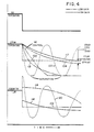
- Figure 4 shows, graphically, the effect on steam temperature (and thus steam quality) of a temperature change in the hot gases supplied to boiler 26.
- the steam temperature will drop; and the steam will rapidly become saturated (undesirable) as shown by curve 100.
- the closed loop, feedback mode of control is employed to compensate for inherent drifts in the predictive flow control equation (drift factors may cause significant errors in the predictive equation).
- Drift may be caused by, for example, miscalibration of valve 72, fouling of steam generating tubes 46 and 48, inaccuracies in the mass flow calculation made by function generator 94, and signific variations in T EX from the assigned value.
- the gain coefficient is assigned a value of 17.8 N/hr/°C, and
- the reason for adopting a variable approach temperature is that a fixed approach temperature does not guarantee a sufficient margin of superheat when gas turbine engine 22 is operating under part load.
- the steam output temperature, T H p is measured by any desired technique, for example by a thermocouple, and summed in an adder 108 with T HP SETPOINT
- Curve 116 in Figure 4 shows how the feedwater flow is regulated when the closed loop correction factor is used in conjunction with the predictive flow value to control valve 72.
- curve 117 shows that this combination of predictive and closed loop modes of operation can be taken advantage of to maintain the steam output temperature at the selected setpoint.
- controller 88 A subsystem for accomplishing this function in controller 88 is illustrated in Figure 3 and identified by reference character 128.
- the flow of steam from boiler 26 is measured and converted to a measured feedwater flow rate in function generator 130.
- This signal is summed with the feedwater flow command signal W FW or W FW TOTAL in adder 132.
- the resulting error signal is converted to a new feedwater flow command signal in a fast response (PID) controller 134; and the new command signal is utilized to operate the electropneumatic actuator of feedwater flow control valve 72.
- PID fast response
- the illustrated boiler 26 is of the dual pressure type, including as it does two independent circuits composed respectively of tubes 46 and 48 in which steam is generated at high and low pressures.
- Optimal operation of a boiler within the principles of the present invention can be furthered by splitting the dual pressure feedwater flow between the tubes 46 and 48 in accord with a particular flow split; viz., that obtained by dividing the high pressure steam flow by the low pressure steam flow.
- the feedwater split or ratio can be determined from the ambient temperature of the air supplied to gas turbine engine compressor 30 and the speed of gas producer turbine 34.
- the values of these two parameters, obtained from sensors 90 and 92, are combined into a flow split signal by function generator 140 in accord with the calculations shown graphically in Figure 5.
- This flow split or ratio signal is applied to the operator (again typically electropneumatic) of a flow proportioning valve 142 in series with feedwater flow control valve 72 see Figure 1) to proportion the flow of feedwater between the high and low pressure steam generating tubes 46 and 48 in boiler 26.
- boiler operation is further optimized by employing feedback to correct the feedwater flow split signal.
- the controller for a dual pressure boiler may have an input for a T LP SETPOINT which is analogous to, and provided for essentially the same purposes as, the Tp SETPOINT discussed above; viz., to insure an adequate degree of superheat in the low pressure steam and maximum recovery of the heat from the hot gases on which boiler 26 is operated.
- the temperature of the low pressure steam is measured, as by a thermocouple, and the resulting signal is summed with that representing T LP SETPOINT adder 143.
- the resulting error signal is converted to a control signal in PI controller 144, and is inverted in inverter 146. This produces a signal which is combined with the feedwater flow split command signal from function generator 140 in adder 148, producing a command signal which is, again, applied to the actuator of proportioning valve 142.
- Still another degree of refinement, and increase in boiler performance, can be obtained in the case of a dual pressure boiler by comparing the actual split of feedwater with the predictive flow split and adjusting flow proportioning valve 142 accordingly.
- This subsystem is shown in Figure 6 and identified by reference character 150.
- the resulting signal is summed with the flow split command signal from function generator 140 or adder 148 in adder 154, producing an error signal which is converted to a command signal in PID controller 156. That signal is inverted in inverter 158 and, as discussed previously, applied to the actuator of flow proportioning valve 142.
- novel feedwater flow controllers described herein are across-the-board applicable to once through, unfired boilers.
- control strategy involves only an energy or enthalpy balance between the hot gases supplied to the boiler and steam generated in the boiler, and as the only variable inputs to the controller can be measured or calculated (gas temperature and mass flow) or can be assigned constant values, it will be readily apparent to the reader that the principles of the present invention are applicable independent of the source of the waste heat.
Landscapes
- Engineering & Computer Science (AREA)
- Chemical & Material Sciences (AREA)
- Combustion & Propulsion (AREA)
- Mechanical Engineering (AREA)
- General Engineering & Computer Science (AREA)
- Physics & Mathematics (AREA)
- Thermal Sciences (AREA)
- Control Of Steam Boilers And Waste-Gas Boilers (AREA)
- Engine Equipment That Uses Special Cycles (AREA)
Abstract
Description
- This invention relates to a steam generation system having a novel control system, particularly a steam generation system for unfired generators (or boilers) of the once-through type.
- Conventional steam boilers have a number of economic shortcomings and cause many operating problems in combined cycle applications, particularly those of small capacity using gas turbines in the 4000-25000 Kw range. Among the major contributors to these drawbacks are the complex systems utilized to control the operation of combined cycle power plant boilers. Typical prior art control systems for combined cycle power plants are disclosed in US-A-3505811 and US-A-2965765.
- The complex prior art boiler control systems tend to have large numbers of components that are subject to malfunction which makes maintenance costs high and reduces boiler availability. Also, attended operation may be required for safe and efficient boiler operation.
- The present invention is directed to overcoming these problems.
- GB-A-1092339 discloses a steam generation system comprising an unfired boiler; a source of thermal energy for the boiler; means for effecting a flow of feedwater to the boiler; a controller for controlling the operation of the boiler and including means operable in a predictive mode of operation for periodically calculating the energy available to the boiler from the thermal energy source and the quantity of dry steam that can be generated by the transfer of the energy to the feedwater; and means under the direction of the controller for so modulating the flow of feedwater to the boiler as to supply to the boiler the quantity of feedwater that can be turned into steam by the transfer of the thermal energy thereto. There is a need to improve the efficiency and response of such a system, and, according to the invention, such a system is characterised in that the boiler has a high pressure steam generating circuit, a low pressure steam generating circuit; in that the means for modulating the flow of feedwater to the boiler includes a feedwater flow proportioning means upstream of the high and low pressure steam generating circuits; and in that the controller has means for generating a predicted flow split signal of the predicted ratio of the flow of feedwater to the high and low pressure steam generating circuits, means for generating first and second signals indicative of the flow of the feedwater actually passed through the boiler and through the low pressure steam generating circuit, means for converting the first and second signals to an actual flow split signal in accordance with the term

- The present invention utilizes the philosophy that an unfired boiler can be so controlled as to efficiently produce steam of acceptable quality by regulating a single operating parameter; viz., the flow of feedwater to the boiler. An energy or enthalpy balance is struck between the hot gases supplied to the boiler and steam at a specified temperature relative to the temperature of those gases (the approach temperature) because steam quality and boiler efficiency are closely related to steam temperature, and the flow of feedwater is so regulated that the steam is produced at the selected (approach setpoint) temperature. The herein disclosed boiler operation controllers are simple, reliable, inexpensive and capable of providing safe and efficient unattended boiler operation.
- In the accompanying drawings:-
- Figure 1 is a schematic view of a combined cycle power plant with a boiler which is adapted to be controlled in accord with the principles of the present invention;
- Figure 2 is a schematic illustration of one controller which can be employed to control the operation of the boiler shown in Figure 1;
- Figure 3 is a schematic illustration of a subsystem that can be added to the controller of Figure 2 to afford more accurate control over the operation of the boiler;
- Figure 4 shows, graphically, the effect of different types of control on boiler operation;
- Figure 5 shows, schematically, a subsystem which can be added to the controller of Figure 2 in applications involving dual pressure boilers to make the operation of the boiler more efficient; and
- Figure 6 is a schematic representation of yet another subsystem that can be used in conjunction with that shown in Figure 5 to make the operation of a dual pressure boiler more efficient.
- Referring now to the drawing, Figure 1 depicts a combined
cycle power plant 20 which includes: agas turbine engine 22 drive connected to analternator 24; aboiler 26, in which steam is generated by thermal energy recovered from the hot gases exhausted fromgas turbine engine 22; and asteam turbine 28 also drive connected toalternator 24 and employing the steam produced inboiler 26 as a motive fluid. - In
power plant 20,steam turbine 28 also drives the exemplary load; in this example analternator 24. However, it can equally well be employed to drive a load which is different from the load being driven bygas turbine engine 22. - For the most part, the components of
power plant 20 are of conventional or otherwise familiar construction. Those components will be described herein only to the extent necessary for an understanding of the present invention. - The illustrated gas turbine engine is of conventional configuration; it includes a
compressor 30, acombustor 32, agas producer turbine 34 fordriving compressor 30, and apower turbine 36. Hot gases exhausted frompower turbine 36 at a temperature in the range of 427-482°C are ducted to, and flow through, thecasing 38 ofsteam generator 26. Normally, these gases will be exhausted to atmosphere throughstack 40 at a temperature of about 112°C. The heat thus recovered insteam generator 26 is 21-25% higher than can be recovered in the unfired boilers, heretofore employed in combined cycle power plants. - The
boiler 26 illustrated in Figure 1 has a once-through, dual pressure configuration. It includes a steam generating module 42 which, in one actual boiler design, is made up of forty steam generating circuit assemblies each including ahigh pressure tube 46 and alow pressure tube 48. In each of these tubes a phase change of water to saturated steam and a change from saturated steam to superheated steam occurs in a continuous flow path extending from the inlet 50 (or 52) to the outlet 54 (or 56) of the tube as the water flows downwardly through the tube in efficient, counterflow relationship to the flow of the hot gas turbine engine exhaust gases. Thus, different regions in each tube function as a feedwater heater, as a vaporizer, and as a superheater. - High pressure steam generated in
tubes 46 ofboiler 26 flows into the high pressure section of dual pressuresteam turbine engine 28, and low pressure steam flows into the low pressure section of the turbine. - A number of desirable attributes such as reduced maintenance and operating costs, simplification of automatic operation, and elimination of possibilities for operator error are obtained by the use of corrosion resistant materials in
boiler 26, thereby eliminating the need for controlling pH and for chemically and/or mechanically controlling the dissolved oxygen content of the boiler feedwater. To this end,tubes - Steam exhausted from
turbine 28 flows into aconventional condenser 62 where the steam is condensed. This component may be, as examples, a water or air cooled condenser of conventional design. - Condensate accumulates in
hot well 64 which contains the small inventory of feedwater needed forboiler 26. - That only a small inventory of feedwater is needed to operate
boiler 26 is of considerable practical importance. The large mass of saturated water contained in the drums of a conventional boiler, and eliminated in the novel boilers disclosed herein, is a safety hazard and has produced widespread legislation requiring attended operation of steam boilers. By eliminating this large mass of saturated water, the requirement for attended operation can also be eliminated. This is cost effective and, also, facilitaes remote, unattended operation of combinedcycle power plant 20. - From
hot well 64, the condensed steam is circulated bycondensate pump 66 to acondensate polisher 68. Here, dissolved solids are removed from the condensate which is then pumped tosteam generator 26 byfeedwater pump 70 through a modulating typeflow control valve 72. This valve is controlled by a system which matches the feedwater flow rate to the enthalpy in the hot gases supplied to the steam generator fromgas turbine 22. - As indicated above, it has unexpectedly been found that the fabrication of those boiler components wetted by aqueous fluids eliminates the need for chemically removing dissolved oxygen from the feedwater supplied to
boiler 26 or for controlling the pH of the feedwater. However, physical removal of dissolved gases as by hot well deaeration will typically be necessary to maintain an adequate pressure drop across the system. Hot well deaeration is effected by avacuum pump 78 connected to hot well 64 throughcondenser 62. Oxygen evacuated from the hot well and condenser by the vacuum pump typically contains appreciable amounts of entrained water. Consequently, the evacuated air is pumped into aconventional separator 80. Air is discharged fromseparator 80 to atmosphere, and water is returned throughtrap 82 fromseparator 80 to condenser 62. - One of the important advantages of the steam generators disclosed herein is that the requirement for make-up of feedwater is nominal. For example, one boiler of the type disclosed herein is planned to produce 6,998 kilograms of steam per hour at one exemplary design point. Make-up water requirements for this boiler are less than 2.4 litres per hour. In contrast, make-up water requirements for a conventional blowdown boiler of comparable capacity are about 170 litres per hour.
- Such make-up water as is required is first circulated through a
demineralizer 84 to remove dissolved and suspended solids from the water and then supplied to hot well 64 through make-up water line 86. - Referring still to the drawing, Figures 2 and 3 show, schematically, one flow control system (or flow controller) 88 for regulating the flow of feedwater to
boiler 26 by modulating the flow of the feedwater throughflow control valve 72. -
Flow controller 88 employs the above-discussed strategy of recovering the maximum amount of thermal energy from the hot gases supplied toboiler 26 without adjusting the flow of fuel to or otherwise predicating the operation ofgas turbine engine 22 on conditions in the boiler; that is, the operation ofboiler 26 is subordinated or slaved to the operation of the gas turbine engine. - This strategy can be followed and safe, efficient operation of
boiler 26 obtained in an extremely simple fashion by controlling only the flow of feedwater to the boiler, this control being so effected as to maintain only one parameter within specified limits. This parameter is the approach temperature ofboiler 26 which is defined as the temperature of the hot gases supplied to the boiler minus the temperature of the high pressure steam generated in the boiler. -
Controller 88 achieves this goal by calculating the energy available from the hot gases supplied toboiler 26 and the maximum amount of steam that can thereby be produced within the foregoing constraint and adjustingfeedwater flow valve 72 accordingly. - The energy added to the feedwater to generate steam equals the energy recoverable from the gas turbine engine exhaust gases. Because outlets 54 and 56 (see Figure 1) are fixed restrictions, that energy balance can be approximated by:

- CPFW =the average specific heat of steam on the water side of the boiler at design point,
- ΔTFW = Tout- Tin=the increase from feedwater temperature to steam outlet temperature,
- hfg =the latent heat of vaporization of water,
- DTgas =the change in temperature of turbine exhaust gases in the boiler,
- WFW =the mass flow of feedwater through the boiler,
- Wgas =the mass flow of hot gas supplied to the boiler from the gas turbine engine as calculated from measured operating parameters of
gas turbine engine 22, and - Cgas =the specific heat of the hot gases supplied to the boiler.
- Certain set points were established to optimize the generation of steam in the
boiler 26 of combinedcycle power plant 20. The first was that the temperature of the gas leaving the boiler should be 105°C. Thus, ΔTgas=Tgas-105°C, where Tgas is the temperature of the gas being supplied toboiler 26 and is a measured parameter. The specific heats Cgas and CpFW were assigned average values of Cgas=0.0025 and CPFW=0.00538. The water inlet temperature, Tin, is relatively constant and was assigned an average value of 33°C. - With the foregoing, the feedwater equation can be rewritten as follows:

- The term hfg is relatively constant and was replaced by an assigned value. As CPFW and Tin are relatively constant, values assigned to these parameters were multiplied together and added algebraically to the value assigned to hfg. The resulting figure was 2.05.
- As discussed above, the maximum amount of dry steam (within constraints) can be produced if THP, the outlet steam temperature, is kept within a specified number of degrees of Tgas. This difference, termed the approach temperature, TAPP= Tgas- THP.
- The expression (THP-Tgas) is preferably replaced by one which takes the wanted approach temperature into account, and is:

- Thus with all assigned values substituted, the feedwater flow control algorithm becomes:

- The only variables in the open loop, predictive mode of operation afforded
flow controller 88 by the feedwater flow control algorithm (3) are the mass flow and temperature of the gases supplied toboiler 26. - The mass flow of exhaust gases available from turbine 22 (Wgas) is proportional to the speed of
gas producer turbine 34 for any given ambient temperature of the air introduced intocompressor 30. - Consequently,
controller 88 is designed to convert the speed and ambient air temperature information fromsensor conventional function generator 94 designed to make the calculations shown in graphical fashion in Figure 2. The Wgas value and the gas temperature (measured by asensor 96 such as a thermocouple) are transmitted to calculation block 98 as is the selected value of THP SETPOINT.Calculation block 98 solves the equation or algorithm (3) discussed above, generating a feedwater flow signal WFw. This signal is transmitted to the (typically) electropneumatic actuator (not shown) offeedwater flow valve 72 to regulate the flow of feedwater toboiler 26 in accord with the operating strategy discussed above. - In one exemplary controller, the input data for the feedwater flow control equation is collected at a rate of ten times per second, and WFW is recalculated after each update in the input data. The significant result of updating the input data and recalculating WFW at this frequency is that the feedwater flow rate is for all practical purposes based on a prediction rather than results at the boiler input. This is important because the transit time of the water through the boiler is measured in minutes; and, if output results were the only control factor, regulation of the feedwater flow would be based on obsolete data.
- Figure 4 shows, graphically, the effect on steam temperature (and thus steam quality) of a temperature change in the hot gases supplied to
boiler 26. In the case of a rapid drop in the exhaust gas temperature and no feedwater control, the steam temperature will drop; and the steam will rapidly become saturated (undesirable) as shown bycurve 100. - On the other hand, if the feedwater flow is regulated by the predictive flow control equation discussed above, the feedwater flow will be decreased as the gas temperature drops as shown by
curve 102. As a result, the steam temperature will stabilize at a temperature approaching the selected setpoint as shown bycurve 104. - Even better control over the generation of steam in
boiler 26 can be gained in some circumstances by adding to the open loop, predictive mode flow control discussed above thefeedback loop 106 shown in Figure 2. Typically, this closed loop mode of control will be made operator selectable. - The closed loop, feedback mode of control is employed to compensate for inherent drifts in the predictive flow control equation (drift factors may cause significant errors in the predictive equation).
- Drift may be caused by, for example, miscalibration of
valve 72, fouling ofsteam generating tubes function generator 94, and signific variations in TEX from the assigned value. - In the closed loop mode of boiler control a corrected feedwater flow rate and a feedwater flow correction factor WCLCF are generated in accord with the equations:


- FWTOTAL =the newly computed feedwater flow including the closed loop correction, in kg/hr,
- THP =the measured high pressure outlet steam temperature, and
- KCLCF =a gain coefficient for converting temperature to feedwater flow.
- The gain coefficient is assigned a value of 17.8 N/hr/°C,


gas turbine engine 22 is operating under part load. - The steam output temperature, THp, is measured by any desired technique, for example by a thermocouple, and summed in an
adder 108 with THP SETPOINT - This produces an error signal which is converted as by a
conventional PI controller 110 into a control signal compatible with that generated infunction generator 98. This latter signal is inverted ininverter 112 and summed with the predictive feedwater flow (WFw) signal inadder 114, producing the new feedwater flow command signal (Fw TOTAL) for operating the electropneumatic actuator of feedwaterflow control valve 72. -
Curve 116 in Figure 4 shows how the feedwater flow is regulated when the closed loop correction factor is used in conjunction with the predictive flow value to controlvalve 72. In the same Figure,curve 117 shows that this combination of predictive and closed loop modes of operation can be taken advantage of to maintain the steam output temperature at the selected setpoint. - It is of course theoretically possible to control feedwater flow solely by the use of a feedback loop as shown in Figure 2 without simultaneously employing predictive flow control. However, Figure 4 makes it clear that this will not provide the desired results; viz., the generation of dry steam and the maximum recovery of thermal energy (which requires that the steam temperature be maintained as closely as possible to the steam temperature setpoint). If the gain in the feedback control is set low, the result of a change in gas temperature as shown in Figure 4 is overdamping as indicated by
curves curves - It is preferred that the actual feedwater flow be measured and that any differences between the measured and command values be employed to correct the feedwater flow. A subsystem for accomplishing this function in
controller 88 is illustrated in Figure 3 and identified byreference character 128. - In this subsystem, the flow of steam from
boiler 26 is measured and converted to a measured feedwater flow rate infunction generator 130. This signal is summed with the feedwater flow command signal WFW or WFW TOTAL inadder 132. The resulting error signal is converted to a new feedwater flow command signal in a fast response (PID)controller 134; and the new command signal is utilized to operate the electropneumatic actuator of feedwaterflow control valve 72. - As discussed above, the illustrated
boiler 26 is of the dual pressure type, including as it does two independent circuits composed respectively oftubes tubes - A subsystem designed to provide this additional degree of control is illustrated in Figure 5 and identified by
reference character 138. - As in the case of predictive feedwater flow, the feedwater split or ratio can be determined from the ambient temperature of the air supplied to gas
turbine engine compressor 30 and the speed ofgas producer turbine 34. The values of these two parameters, obtained fromsensors function generator 140 in accord with the calculations shown graphically in Figure 5. This flow split or ratio signal is applied to the operator (again typically electropneumatic) of aflow proportioning valve 142 in series with feedwaterflow control valve 72 see Figure 1) to proportion the flow of feedwater between the high and low pressuresteam generating tubes boiler 26.. - Also, in the case of dual pressure boiler, boiler operation is further optimized by employing feedback to correct the feedwater flow split signal.
- Specifically, as shown in Figure 5, the controller for a dual pressure boiler may have an input for a TLP SETPOINT which is analogous to, and provided for essentially the same purposes as, the Tp SETPOINT discussed above; viz., to insure an adequate degree of superheat in the low pressure steam and maximum recovery of the heat from the hot gases on which
boiler 26 is operated. - In the feedback mode of operation, which again is preferably operator selectable, the temperature of the low pressure steam is measured, as by a thermocouple, and the resulting signal is summed with that representing TLP SETPOINT adder 143.
- The resulting error signal is converted to a control signal in
PI controller 144, and is inverted ininverter 146. This produces a signal which is combined with the feedwater flow split command signal fromfunction generator 140 inadder 148, producing a command signal which is, again, applied to the actuator ofproportioning valve 142. - Still another degree of refinement, and increase in boiler performance, can be obtained in the case of a dual pressure boiler by comparing the actual split of feedwater with the predictive flow split and adjusting
flow proportioning valve 142 accordingly. This subsystem is shown in Figure 6 and identified byreference character 150. - In the illustrated subsystem, the flow of high pressure and low pressure steam from
boiler 26 are measured and signals indicative of the resulting mass flows converted to a flow split value infunction generator 152 in accord with the equation:
- WLPFW =the low pressure steam flow, and
- WFW-WLPFW=the high pressure steam flow.
- The resulting signal is summed with the flow split command signal from
function generator 140 oradder 148 inadder 154, producing an error signal which is converted to a command signal inPID controller 156. That signal is inverted ininverter 158 and, as discussed previously, applied to the actuator offlow proportioning valve 142. - It is reiterated, in conjunction with the foregoing detailed description that the novel feedwater flow controllers described herein are across-the-board applicable to once through, unfired boilers. In particular, as the control strategy involves only an energy or enthalpy balance between the hot gases supplied to the boiler and steam generated in the boiler, and as the only variable inputs to the controller can be measured or calculated (gas temperature and mass flow) or can be assigned constant values, it will be readily apparent to the reader that the principles of the present invention are applicable independent of the source of the waste heat.
Claims (5)


flow control means (72) for modulating the flow of feedwater to the boiler at the rate WFW calculated by the controller (88) and thereby supplying to the boiler (26) the quantity of feedwater that can be turned into the steam by the transfer of the thermal energy thereto from the hot gases.


Applications Claiming Priority (2)
| Application Number | Priority Date | Filing Date | Title |
|---|---|---|---|
| US49713283A | 1983-05-23 | 1983-05-23 | |
| US497132 | 1983-05-23 |
Publications (2)
| Publication Number | Publication Date |
|---|---|
| EP0147407A1 EP0147407A1 (en) | 1985-07-10 |
| EP0147407B1 true EP0147407B1 (en) | 1988-06-01 |
Family
ID=23975602
Family Applications (1)
| Application Number | Title | Priority Date | Filing Date |
|---|---|---|---|
| EP19840901679 Expired EP0147407B1 (en) | 1983-05-23 | 1984-04-02 | Steam generator control systems |
Country Status (5)
| Country | Link |
|---|---|
| EP (1) | EP0147407B1 (en) |
| JP (1) | JPH0663606B2 (en) |
| BR (1) | BR8406845A (en) |
| DE (1) | DE3471732D1 (en) |
| WO (1) | WO1984004797A1 (en) |
Cited By (1)
| Publication number | Priority date | Publication date | Assignee | Title |
|---|---|---|---|---|
| US9696098B2 (en) | 2012-01-17 | 2017-07-04 | General Electric Technology Gmbh | Method and apparatus for connecting sections of a once-through horizontal evaporator |
Families Citing this family (3)
| Publication number | Priority date | Publication date | Assignee | Title |
|---|---|---|---|---|
| DE19506727A1 (en) * | 1995-02-27 | 1996-08-29 | Abb Management Ag | Process for operating a power plant |
| WO1996028689A1 (en) * | 1995-03-16 | 1996-09-19 | Siemens Aktiengesellschaft | Method and device for monitoring the feed-water supply to a steamgenerator |
| EP2805109B1 (en) | 2012-01-17 | 2019-08-14 | General Electric Technology GmbH | Start-up system for a once-through horizontal evaporator |
Family Cites Families (11)
| Publication number | Priority date | Publication date | Assignee | Title |
|---|---|---|---|---|
| FR1288316A (en) * | 1961-03-22 | 1962-03-24 | Babcock & Wilcox Ltd | Process and plant for the production of superheated steam |
| FR1417161A (en) * | 1964-08-13 | 1965-11-12 | Electricite De France | Process for regulating the temperature of a fluid heated by heat exchange with a heating fluid, in particular in a nuclear installation |
| JPS459442Y1 (en) * | 1968-10-30 | 1970-05-04 | ||
| US3769795A (en) * | 1972-03-22 | 1973-11-06 | Turbo Power And Marines Syst I | Multipressure steam system for unfired combined cycle powerplant |
| DE2421003A1 (en) * | 1974-04-30 | 1975-11-13 | Siemens Ag | Adjustment of steam-generating heat-exchanger - has actual enthalpy control and measures pressure at one line-point, temperature at all line-points |
| JPS55150401A (en) * | 1979-04-09 | 1980-11-22 | Mitsui Shipbuilding Eng | Control method of waste heat regeneration system |
| JPS57174601A (en) * | 1981-04-22 | 1982-10-27 | Mitsubishi Heavy Ind Ltd | Exhaust gas economizer |
| JPS57188901A (en) * | 1981-05-16 | 1982-11-20 | Babcock Hitachi Kk | Recovery boiler for waste heat from gas turbine |
| GB2099558A (en) * | 1981-05-26 | 1982-12-08 | Gen Electric | Heat recovery steam generator |
| JPS5815703A (en) * | 1981-07-22 | 1983-01-29 | Hitachi Ltd | Method of controlling plant |
| JPS5822804A (en) * | 1981-07-31 | 1983-02-10 | 三菱重工業株式会社 | Controller for temperature of steam in case of pressure change operation |
-
1984
- 1984-04-02 BR BR8406845A patent/BR8406845A/en not_active IP Right Cessation
- 1984-04-02 DE DE8484901679T patent/DE3471732D1/en not_active Expired
- 1984-04-02 EP EP19840901679 patent/EP0147407B1/en not_active Expired
- 1984-04-02 JP JP59501693A patent/JPH0663606B2/en not_active Expired - Lifetime
- 1984-04-02 WO PCT/US1984/000499 patent/WO1984004797A1/en not_active Ceased
Cited By (1)
| Publication number | Priority date | Publication date | Assignee | Title |
|---|---|---|---|---|
| US9696098B2 (en) | 2012-01-17 | 2017-07-04 | General Electric Technology Gmbh | Method and apparatus for connecting sections of a once-through horizontal evaporator |
Also Published As
| Publication number | Publication date |
|---|---|
| JPH0663606B2 (en) | 1994-08-22 |
| BR8406845A (en) | 1985-04-16 |
| DE3471732D1 (en) | 1988-07-07 |
| EP0147407A1 (en) | 1985-07-10 |
| WO1984004797A1 (en) | 1984-12-06 |
| JPS60501422A (en) | 1985-08-29 |
Similar Documents
| Publication | Publication Date | Title |
|---|---|---|
| US5237816A (en) | Steam generator control systems | |
| CA1218699A (en) | Heat recovery steam generator outlet temperature control system for a combined cycle power plant | |
| US4576124A (en) | Apparatus and method for fluidly connecting a boiler into pressurized steam feed line and combined-cycle steam generator power plant embodying the same | |
| EP0285297B1 (en) | Boiler steam temperature controller | |
| EP0093724B1 (en) | Sliding pressure flash tank | |
| KR20130115281A (en) | Method for operating a combined gas and steam turbine system, gas and steam turbine system for carrying out said method, and corresponding control device | |
| JPH0665921B2 (en) | Boiler start control device | |
| EP0194568B1 (en) | Automatic control system for thermal power plant | |
| WO1984004797A1 (en) | Steam generator control systems | |
| CA1221754A (en) | Steam generator control systems | |
| US5850740A (en) | Fluidized bed power plant, and control apparatus and method thereof | |
| JP3061289B2 (en) | Process predictive control method and predictive control system | |
| JPH10299424A (en) | Waste incineration power plant steam temperature control method | |
| JPH05296401A (en) | Exhaust heat recoverying boiler system and its main steam temperature controller | |
| CA1211324A (en) | Control system for variable pressure once-through boiler | |
| JP3820636B2 (en) | Method and apparatus for controlling feed water temperature in exhaust recombustion combined cycle plant | |
| JPH0754611A (en) | Denitration control device | |
| SU885703A1 (en) | System for controlling steam temperature after heat generating unit undustrial superheater | |
| Kaya et al. | Methods of energy efficient control and optimization for combined-cycle cogeneration | |
| AU2024331549A1 (en) | Preventing varying pressure loading of a steam generator in standby mode | |
| JP2507426B2 (en) | Coal gasification combined cycle controller | |
| JPH0754082B2 (en) | Water pump drive turbine pressure control device | |
| JPS5822804A (en) | Controller for temperature of steam in case of pressure change operation | |
| JPS62264568A (en) | Temperature control of reformer for fuel cell plant | |
| JPH0226122B2 (en) |
Legal Events
| Date | Code | Title | Description |
|---|---|---|---|
| PUAI | Public reference made under article 153(3) epc to a published international application that has entered the european phase |
Free format text: ORIGINAL CODE: 0009012 |
|
| 17P | Request for examination filed |
Effective date: 19841120 |
|
| AK | Designated contracting states |
Designated state(s): CH DE FR GB LI SE |
|
| 17Q | First examination report despatched |
Effective date: 19860320 |
|
| GRAA | (expected) grant |
Free format text: ORIGINAL CODE: 0009210 |
|
| AK | Designated contracting states |
Kind code of ref document: B1 Designated state(s): CH DE FR GB LI SE |
|
| REF | Corresponds to: |
Ref document number: 3471732 Country of ref document: DE Date of ref document: 19880707 |
|
| ET | Fr: translation filed | ||
| PLBE | No opposition filed within time limit |
Free format text: ORIGINAL CODE: 0009261 |
|
| STAA | Information on the status of an ep patent application or granted ep patent |
Free format text: STATUS: NO OPPOSITION FILED WITHIN TIME LIMIT |
|
| 26N | No opposition filed | ||
| EAL | Se: european patent in force in sweden |
Ref document number: 84901679.5 |
|
| REG | Reference to a national code |
Ref country code: GB Ref legal event code: IF02 |
|
| PGFP | Annual fee paid to national office [announced via postgrant information from national office to epo] |
Ref country code: GB Payment date: 20030313 Year of fee payment: 20 |
|
| PGFP | Annual fee paid to national office [announced via postgrant information from national office to epo] |
Ref country code: FR Payment date: 20030403 Year of fee payment: 20 |
|
| PGFP | Annual fee paid to national office [announced via postgrant information from national office to epo] |
Ref country code: SE Payment date: 20030407 Year of fee payment: 20 |
|
| PGFP | Annual fee paid to national office [announced via postgrant information from national office to epo] |
Ref country code: DE Payment date: 20030430 Year of fee payment: 20 |
|
| PGFP | Annual fee paid to national office [announced via postgrant information from national office to epo] |
Ref country code: CH Payment date: 20030604 Year of fee payment: 20 |
|
| PG25 | Lapsed in a contracting state [announced via postgrant information from national office to epo] |
Ref country code: SE Free format text: LAPSE BECAUSE OF NON-PAYMENT OF DUE FEES Effective date: 20031219 |
|
| PG25 | Lapsed in a contracting state [announced via postgrant information from national office to epo] |
Ref country code: LI Free format text: LAPSE BECAUSE OF EXPIRATION OF PROTECTION Effective date: 20040401 Ref country code: GB Free format text: LAPSE BECAUSE OF EXPIRATION OF PROTECTION Effective date: 20040401 Ref country code: CH Free format text: LAPSE BECAUSE OF EXPIRATION OF PROTECTION Effective date: 20040401 |
|
| REG | Reference to a national code |
Ref country code: GB Ref legal event code: PE20 |
|
| REG | Reference to a national code |
Ref country code: CH Ref legal event code: PL |
|
| EUG | Se: european patent has lapsed |