EP0147397B1 - Differential mechanisms - Google Patents
Differential mechanisms Download PDFInfo
- Publication number
- EP0147397B1 EP0147397B1 EP83903301A EP83903301A EP0147397B1 EP 0147397 B1 EP0147397 B1 EP 0147397B1 EP 83903301 A EP83903301 A EP 83903301A EP 83903301 A EP83903301 A EP 83903301A EP 0147397 B1 EP0147397 B1 EP 0147397B1
- Authority
- EP
- European Patent Office
- Prior art keywords
- members
- clutch
- output
- formations
- blocker
- Prior art date
- Legal status (The legal status is an assumption and is not a legal conclusion. Google has not performed a legal analysis and makes no representation as to the accuracy of the status listed.)
- Expired
Links
Images


Classifications
-
- F—MECHANICAL ENGINEERING; LIGHTING; HEATING; WEAPONS; BLASTING
- F16—ENGINEERING ELEMENTS AND UNITS; GENERAL MEASURES FOR PRODUCING AND MAINTAINING EFFECTIVE FUNCTIONING OF MACHINES OR INSTALLATIONS; THERMAL INSULATION IN GENERAL
- F16H—GEARING
- F16H48/00—Differential gearings
- F16H48/12—Differential gearings without gears having orbital motion
- F16H48/14—Differential gearings without gears having orbital motion with cams
- F16H48/142—Differential gearings without gears having orbital motion with cams consisting of linked clutches using axially movable inter-engaging parts
Definitions
- This invention relates to vehicle differeotial mechanisms of the automatic de-clutching type in which drive to one of the two output members of the mechanism is automatically declutched upon overrunning or underrunning of either output member.
- a vehicle differential mechanism comprising a rotatable input member for connection with a drive means; a rotatable left hand output member and a rotatable right hand output member for connection with components to be driven by the mechanism, the output members being located co-axially one on each side of the input member; a rotatable left hand clutch member and a rotatable right hand clutch member located coaxially one on each side of the input member between the input member and the left hand and right hand output member respectively and slidable relative thereto in directions parallel to said axis of rotation, each clutch member having separate first and second circumferentially-spaced axially-projecting cam formations for engagement with first and second cam formations on the input and output members respectively, said cam formations being shaped to result in axial diplacement of the clutch member on relative rotation between interengaging cam formations; blocking means for controlling the maximum possible rotational movement of the clutch members relative to the input member; the arrangement being such that when the output members rotate in synchronism
- One of the main applications for a differential mechanism in accordance with the present invention is as an inter-wheel differential.
- the output members are connected with respective wheels of a vehicle axle so that when the vehicle is driven substantially in a straight line (when the wheels and thus the output members rotate substantially in synchronism) both output members are driven, but when the vehicle makes a turn, the output member connected with the outer wheel of the turn will rotate faster than the other output member so that drive to the outer wheel is disconnected during the turn and the outer wheel simply over-runs.
- the above arrangement is particularly compact since the friction members are disposed within the clutch members and is relatively simple and inexpensive to produce.
- the blocking means may comprise a blocker member supported co-axially with the clutch members and provided with two series of circumferentially-spaced blocker formations, each respective series of formations engaging a mating set of blocker formations on a respective one of the clutch members, the circumferential spacing between adjacent blocker formations on the blocker member and clutch members limiting the maximum possible relative rotation between the clutch members and hence controlling the maximum possible relative rotation between either clutch member and the input member.
- the friction members may conveniently be connected with the blocker formations of the clutch members.
- Means are preferably provided for preventing the simultaneous disconnection of drive to both output members.
- the invention also provides a vehicle axle including a differential mechanism in accordance with the invention employed as an inter-wheel differential with each output member connected with a respective wheel-driving shaft.
- Figure 1 shows the centre portion of a tractor front axle having a casing 15 into which drive is transmitted via a bevel wheel 10 which meshes with a crownwheel 11 which is bolted to a differential housing 12.
- Drive is transmitted from the differential housing 12 to one or both front wheel drive shafts 13, 14 via a differential mechanism in accordance with the present invention.
- the differential mechanism shown on a larger scale in Figure 2, has the following main components:-
- An input member 16 which bolted between left and right hand parts (12a, 12b) of the differential housing 12 by a series of six circumferentially spaced bolts 50 and a series of six circumferentially spaced dowells 51 which are circumferentially inter-leaved between the bolts;
- Left and right hand output members 17 and 18 which are splined onto left and right hand drive shafts 13 and 14 respectively;
- Left and right hand clutch members 19 and 20 which, when engaged, transmit drive from the central input member 16 to the left and right hand output members 17 and 18 respectively;
- a blocker member in the form of a ring or sleeve 21 which controls the maximum possible relative rotation between clutch members 19 and 20 and hence the maximum possible rotation of either clutch member relative to the input member, and
- Friction members 60 and 61 which are splined onto blocker teeth 26 and 27 of clutch members 19 and 20 and have frusto-conical friction surfaces 60a and 61a respectively which are biased into contact with corresponding frusto-conical surfaces 17a and 18a on output members 17 and 18 by a spring 62. Friction members 60 and 61 provide a light friction drive between clutch members 19 and 20 and their respective output members 17 and 18 as will be described below.
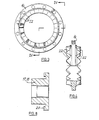
- the input member 16 has cam teeth 22 on each side which are engageable with cam teeth 23 on the adjacent faces of clutch members 19 and 20 shown in Figures 5 and 6.
- Cam teeth 23 are inclined at approximately 45 degrees to the general planes of rotation of clutch members 19 and 20.
- the other faces of the clutch members have smaller cam teeth 24 engageable with cam teeth 25 on the output members 17 and 18, shown in Figure 8.
- Cam teeth 24 are inclined at approximately 60 degrees to the general planes of rotation of clutch members 19 and 20.
- the angles of cam teeth 23 and 24 ensure that the separating force between the input member 16 and the clutch members 19 and 20 due to a given input torque is greater than the separating force between the clutch members and the output members 17 and 18 for the same torque. This ensures that engagement is maintained between the clutch members and the output members in the driving condition described below.
- Each clutch member 19, 20 is also provided on its inside diameter with blocker formations in the form of the blocker teeth 26, 27 respectively for co-operation with two series of blocker formations in the blocker ring 21 in the form of slots 28 and 29 to limit the relative rotational movement possible between the two clutch members as will be described below.
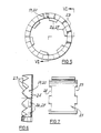
- this shows a diagrammatic development of the view from the inside of the differential mechanism looking radially outwards (i.e., in the direction of arrow A of Figure 1) with the blocker ring 21 shown in dotted detail for clarity and those portions of the output members 17 and 18 radially inward of the blocker ring removed.
- Figure 9 shows the normal straight-ahead driving condition in which the differential housing 12 is rotating so that input member 16 moves in effect in direction X.
- Drive is therefore transmitted via the contact zones 22a and 22b of cam teeth 22 and 23 from input member 16 to both clutch members 19 and 20 and hence via cam teeth 24 and 25 to both output members 17 and 18 and hence both drive shafts 13 and 14.
- both drive shafts are driven in this condition.
- Rotation in direction Y of clutch member 19 relative to input member 16 is limited by contact between the blocker teeth 26 on clutch member 19 and sides 40 of the slots 28 in blocker ring 21 and by contact between the blocker teeth 27 on clutch member 20 and sides 41 of the slots 29 in blocker ring 21.
- blocker ring 21 and cooperating teeth 26 and 27 directly limit the maximum possible relative rotation between the two clutch members.
- the blocker member 21 and teeth 26 and 27 are capable of limiting the maximum possible rotation of either clutch member relative to the input member depending on the direction of the turn.
- the axial distance W (See Figure 10) between the bottoms of the slots 28 and 29 in the blocker ring 21 limits the minimum possible distance between the two sets of blocker teeth 26 and 27 and hence the clutch members to prevent the simultaneous disconnection of drive from both outside members 17 and 18. It will be seen from Figure 10 that with clutch member 19 disconnected from output member 17, the blocker teeth 26 are in contact with the bottoms of slots 28 whilst the axial clearance between the blocker teeth 27 and the bottoms of slots 29 is less than the axial movement of clutch member 20 required to disconnect the drive from output member 18. Thus at least one of the output members is always connected with the input member.
- the light friction drive provided between the clutch members 19 and 20 and their respective output members 17 and 18 by the friction members 60 and 61 provides the necessary level of frictional drive in a torsional sense between the clutch members and the output members via surfaces 60a, 17a and 61a, 18a to assist in re-establishing contact between teeth 22 and 23 when a turn is completed whilst allowing the clutch members to move axially without friction.
- the differential mechanism will cause one or both wheels to be driven by the crownwheel, but at any time either wheel (but not both) can over-run if the tractor is turning a corner. If the tractor is descending a steep hill, and the transmission is resisting the forward movement, this device will cause one or both wheels to be resisted by the crownwheel, but either wheel can "under-run” when turning a corner.
- the present invention provides an improved form of vehicle differential mechanism which is of a relatively simple construction and which is reliable in operation.
- the differential mechanism is compact with the input member 16, clutch members 19, 20, friction members 60, 61 and blocker member 21 all being of annular form and surrounding the central axially-adjacent portions 17b, 18b of the output members with the spring 62 between the blocker member 21 and the central portions 17b, 18b of the output members.
- the toothed components can be produced by forming processes such as casting, forging or sintering without the need for expensive tooth machining.
Landscapes
- Engineering & Computer Science (AREA)
- General Engineering & Computer Science (AREA)
- Mechanical Engineering (AREA)
- Retarders (AREA)
- Arrangement And Driving Of Transmission Devices (AREA)
Abstract
Description
- This invention relates to vehicle differeotial mechanisms of the automatic de-clutching type in which drive to one of the two output members of the mechanism is automatically declutched upon overrunning or underrunning of either output member.
- Differential mechanisms of this type are well known and examples can be found, for example, in US-A-2329059. To date, such mechanisms have been of a relatively complex and thus expensive construction, for example DE-B-1047635 and GB-A-2083875. FR-A-2475660 also relates to a differential mechanism of this type and US-A-2509560 discloses a differential according to the first part of claim 1.
- It is an object of the present invention to provide an improved form of vehicle differential mechanism which is of a relatively simple and reliable construction.
- Thus, according to the present invention there is provided a vehicle differential mechanism comprising a rotatable input member for connection with a drive means; a rotatable left hand output member and a rotatable right hand output member for connection with components to be driven by the mechanism, the output members being located co-axially one on each side of the input member; a rotatable left hand clutch member and a rotatable right hand clutch member located coaxially one on each side of the input member between the input member and the left hand and right hand output member respectively and slidable relative thereto in directions parallel to said axis of rotation, each clutch member having separate first and second circumferentially-spaced axially-projecting cam formations for engagement with first and second cam formations on the input and output members respectively, said cam formations being shaped to result in axial diplacement of the clutch member on relative rotation between interengaging cam formations; blocking means for controlling the maximum possible rotational movement of the clutch members relative to the input member; the arrangement being such that when the output members rotate in synchronism the first cam formations force both sets of second cam formations into engagement to transmit drive to each output member from the input member via the first and second cam formations, and when relative rotation occurs between the output members by virtue of their connection with said components, the second cam formations of the faster rotating output member cause axial and rotational displacement of the associated clutch member thus disconnecting drive between the associated first and second cam formations to disconnect drive between the input member and the faster rotating output member, the blocking means controlling the rotational displacement of said clutch member to prevent re-establishment of contact between the disconnected first cam formations whilst relative rotation occurs between the output members; and a torsional friction drive between each clutch member and its associated output member to assist in re-establishing drive to a disconnected output member on re-establishing of synchronous output member rotation, the differential mechanism being characterised in that a friction member is axially slidably connected for rotation with each clutch member, the friction members being disposed coaxially within the clutch members and being spring-biassed axially apart into frictional contact with a corresponding friction surface on the associated output member to provide said torsional friction drive.
- One of the main applications for a differential mechanism in accordance with the present invention is as an inter-wheel differential. When used in this application the output members are connected with respective wheels of a vehicle axle so that when the vehicle is driven substantially in a straight line (when the wheels and thus the output members rotate substantially in synchronism) both output members are driven, but when the vehicle makes a turn, the output member connected with the outer wheel of the turn will rotate faster than the other output member so that drive to the outer wheel is disconnected during the turn and the outer wheel simply over-runs.
- The above arrangement is particularly compact since the friction members are disposed within the clutch members and is relatively simple and inexpensive to produce.
- The blocking means may comprise a blocker member supported co-axially with the clutch members and provided with two series of circumferentially-spaced blocker formations, each respective series of formations engaging a mating set of blocker formations on a respective one of the clutch members, the circumferential spacing between adjacent blocker formations on the blocker member and clutch members limiting the maximum possible relative rotation between the clutch members and hence controlling the maximum possible relative rotation between either clutch member and the input member.
- The friction members may conveniently be connected with the blocker formations of the clutch members.
- Means are preferably provided for preventing the simultaneous disconnection of drive to both output members.
- The invention also provides a vehicle axle including a differential mechanism in accordance with the invention employed as an inter-wheel differential with each output member connected with a respective wheel-driving shaft.
- One embodiment of the present invention, as applied to tractor front axle, will now be described, by way of example only, with reference to the accompanying drawings in which:-
- Figure 1 shows a horizontal section through the centre portion of the tractor front axle;
- Figure 2 shows the differential mechanism used in the axle of Figure 1 on a larger scale;
- Figure 3 shows a side view of the input member of the differential mechanism;
- Figure 4 shows a part-section on the line IV-IV of Figure 3.
- Figure 5 shows a side view of the clutch member of the differential mechanism;
- Figure 6 shows a part-section on the line VI-VI of Figure 5;
- Figure 7 is a diametral section through the blocker member of the differential mechanism;
- Figure 8 is a diametral section through an output member of the differential mechanism, and
- Figures 9 and 10 show, for the purpose of explanation of the operation of the differential mechanism, diagrammatic developments of the differential mechanism in straight-ahead and turn conditions respectively.
- Figure 1 shows the centre portion of a tractor front axle having a
casing 15 into which drive is transmitted via abevel wheel 10 which meshes with a crownwheel 11 which is bolted to adifferential housing 12. Drive is transmitted from thedifferential housing 12 to one or both frontwheel drive shafts - The differential mechanism, shown on a larger scale in Figure 2, has the following main components:-
- An
input member 16 which bolted between left and right hand parts (12a, 12b) of thedifferential housing 12 by a series of six circumferentially spacedbolts 50 and a series of six circumferentially spaceddowells 51 which are circumferentially inter-leaved between the bolts; - Left and right
hand output members hand drive shafts - Left and right
hand clutch members central input member 16 to the left and righthand output members - A blocker member in the form of a ring or
sleeve 21 which controls the maximum possible relative rotation betweenclutch members -
Friction members blocker teeth clutch members conical surfaces 17a and 18a onoutput members spring 62.Friction members clutch members respective output members - As can be seen from Figures 2, 3 and 4, the
input member 16 hascam teeth 22 on each side which are engageable withcam teeth 23 on the adjacent faces ofclutch members Cam teeth 23 are inclined at approximately 45 degrees to the general planes of rotation ofclutch members smaller cam teeth 24 engageable withcam teeth 25 on theoutput members Cam teeth 24 are inclined at approximately 60 degrees to the general planes of rotation ofclutch members cam teeth input member 16 and theclutch members output members - Each
clutch member blocker teeth blocker ring 21 in the form ofslots - Referring to Figure 9, this shows a diagrammatic development of the view from the inside of the differential mechanism looking radially outwards (i.e., in the direction of arrow A of Figure 1) with the
blocker ring 21 shown in dotted detail for clarity and those portions of theoutput members - Figure 9 shows the normal straight-ahead driving condition in which the
differential housing 12 is rotating so thatinput member 16 moves in effect in direction X. Drive is therefore transmitted via the contact zones 22a and 22b ofcam teeth input member 16 to bothclutch members cam teeth output members drive shafts - If the vehicle now makes a turn which results in the outside wheel (the left-hand wheel as shown in Figure 10) rotating faster than the inside (righthand) wheel, the contact between
input member 16 andclutch member 19 will be lost since the clutch member will tend to rotate in the forward drive direction relative to theinput member 16 as indicated by arrow Y. - Rotation in direction Y of
clutch member 19 relative toinput member 16 is limited by contact between theblocker teeth 26 onclutch member 19 andsides 40 of theslots 28 inblocker ring 21 and by contact between theblocker teeth 27 onclutch member 20 andsides 41 of theslots 29 inblocker ring 21. - When further rotation of
clutch member 19 relative toinput member 16 is prevented by contact betweenteeth 26 and theslot sides 40 as described above, the continued rotation ofoutput member 17 due to its connection with the associated wheel causes a cam action betweenteeth teeth teeth - The above described limitation of the maximum possible relative rotation between
clutch member 19 andinput member 16 is arranged to prevent contact betweensides 23d ofteeth 23 andsides 22d ofteeth 22 during a turn (which would camclutch member 19 outwardly to re-engageteeth 24 and 25). - As will be appreciated, blocker
ring 21 and cooperatingteeth input member 16 during a turn, theblocker member 21 andteeth - On completion of the turn the speed differential between
output members clutch member 19 moves in the opposite direction to arrow Y to re-establish contact with theteeth 22 ofinput member 16 so thatteeth clutch member 19 in the opposite direction to arrow Z to re-engageteeth member 17. - It will be noted that the axial distance W (See Figure 10) between the bottoms of the
slots blocker ring 21 limits the minimum possible distance between the two sets ofblocker teeth outside members clutch member 19 disconnected fromoutput member 17, theblocker teeth 26 are in contact with the bottoms ofslots 28 whilst the axial clearance between theblocker teeth 27 and the bottoms ofslots 29 is less than the axial movement ofclutch member 20 required to disconnect the drive fromoutput member 18. Thus at least one of the output members is always connected with the input member. - The light friction drive provided between the
clutch members respective output members friction members surfaces 60a, 17a and 61a, 18a to assist in re-establishing contact betweenteeth - Thus in operation the differential mechanism will cause one or both wheels to be driven by the crownwheel, but at any time either wheel (but not both) can over-run if the tractor is turning a corner. If the tractor is descending a steep hill, and the transmission is resisting the forward movement, this device will cause one or both wheels to be resisted by the crownwheel, but either wheel can "under-run" when turning a corner.
- In the drive condition during a turn only the inside wheel is driven whilst in an overrunning condition during a turn only the outside wheel is resisted.
- It will be appreciated from the above that the present invention provides an improved form of vehicle differential mechanism which is of a relatively simple construction and which is reliable in operation. The differential mechanism is compact with the
input member 16,clutch members friction members blocker member 21 all being of annular form and surrounding the central axially-adjacent portions 17b, 18b of the output members with thespring 62 between theblocker member 21 and the central portions 17b, 18b of the output members. - Also since none of the teeth used in the mechanism have re-entrant angles, the toothed components can be produced by forming processes such as casting, forging or sintering without the need for expensive tooth machining.
- Although the invention has been described above in relation to a tractor front axle inter-wheel differential, it will be evident that it has wider application. For example, it is also suitable for use as an inter-wheel differential in the rear axle of a four wheel drive vehicle and also as an inter-axle differential.
Claims (8)
Applications Claiming Priority (2)
| Application Number | Priority Date | Filing Date | Title |
|---|---|---|---|
| GB8229439 | 1982-10-14 | ||
| GB8229439 | 1982-10-14 |
Publications (2)
| Publication Number | Publication Date |
|---|---|
| EP0147397A1 EP0147397A1 (en) | 1985-07-10 |
| EP0147397B1 true EP0147397B1 (en) | 1988-05-25 |
Family
ID=10533611
Family Applications (1)
| Application Number | Title | Priority Date | Filing Date |
|---|---|---|---|
| EP83903301A Expired EP0147397B1 (en) | 1982-10-14 | 1983-10-11 | Differential mechanisms |
Country Status (8)
| Country | Link |
|---|---|
| EP (1) | EP0147397B1 (en) |
| DE (1) | DE3376757D1 (en) |
| ES (1) | ES526476A0 (en) |
| GB (1) | GB2130315B (en) |
| IN (1) | IN161621B (en) |
| IT (1) | IT1214448B (en) |
| WO (1) | WO1984001608A1 (en) |
| ZA (1) | ZA837339B (en) |
Families Citing this family (3)
| Publication number | Priority date | Publication date | Assignee | Title |
|---|---|---|---|---|
| FR2885656B1 (en) * | 2005-05-13 | 2009-05-15 | France Reducteurs Sa Sa | TRANSMISSION HOUSING FOR A ROLLING MACHINE, IN PARTICULAR A WALKING CONDUCTOR |
| FR2885655B1 (en) * | 2005-05-13 | 2007-06-29 | France Reducteurs Sa Sa | PERFECTIONED TRANSMISSION HOUSING FOR ROLLER |
| FR2997157B1 (en) | 2012-10-18 | 2014-11-28 | France Reducteurs | DIFFERENTIAL DEVICE FOR MOTORIZED RUNNING GEAR |
Citations (1)
| Publication number | Priority date | Publication date | Assignee | Title |
|---|---|---|---|---|
| US2509560A (en) * | 1946-10-02 | 1950-05-30 | Frank M Lewis | Differential mechanism |
Family Cites Families (5)
| Publication number | Priority date | Publication date | Assignee | Title |
|---|---|---|---|---|
| GB291942A (en) * | 1927-05-23 | 1928-06-14 | Frank Marshall Lewis | Improvements in differential mechanism |
| US2830466A (en) * | 1955-12-12 | 1958-04-15 | Patent Developers Inc | Differential mechanism |
| US3397593A (en) * | 1966-04-19 | 1968-08-20 | Frederick D. Knoblock | Differential |
| FR2475660A1 (en) * | 1979-05-30 | 1981-08-14 | Lacrosse Valentin | Automatically locking differential gear train - uses floating sprung spoked dog-wheel between double crown wheel and each output pinion |
| US4424725A (en) * | 1980-09-19 | 1984-01-10 | Tractech, Inc. | Locking differential mechanism with improved holdout ring and spring retainer |
-
1983
- 1983-09-30 IN IN1207/CAL/83A patent/IN161621B/en unknown
- 1983-09-30 ZA ZA837339A patent/ZA837339B/en unknown
- 1983-10-11 GB GB08327114A patent/GB2130315B/en not_active Expired
- 1983-10-11 DE DE8383903301T patent/DE3376757D1/en not_active Expired
- 1983-10-11 WO PCT/GB1983/000256 patent/WO1984001608A1/en not_active Ceased
- 1983-10-11 EP EP83903301A patent/EP0147397B1/en not_active Expired
- 1983-10-14 ES ES526476A patent/ES526476A0/en active Granted
- 1983-10-14 IT IT8323315A patent/IT1214448B/en active
Patent Citations (1)
| Publication number | Priority date | Publication date | Assignee | Title |
|---|---|---|---|---|
| US2509560A (en) * | 1946-10-02 | 1950-05-30 | Frank M Lewis | Differential mechanism |
Also Published As
| Publication number | Publication date |
|---|---|
| ES8503095A1 (en) | 1985-02-01 |
| GB2130315B (en) | 1986-02-05 |
| EP0147397A1 (en) | 1985-07-10 |
| IT8323315A0 (en) | 1983-10-14 |
| ZA837339B (en) | 1985-05-29 |
| ES526476A0 (en) | 1985-02-01 |
| GB8327114D0 (en) | 1983-11-09 |
| DE3376757D1 (en) | 1988-06-30 |
| WO1984001608A1 (en) | 1984-04-26 |
| IN161621B (en) | 1988-01-02 |
| IT1214448B (en) | 1990-01-18 |
| GB2130315A (en) | 1984-05-31 |
Similar Documents
| Publication | Publication Date | Title |
|---|---|---|
| EP0262434B1 (en) | Interaxle differential restriction device for vehicle four wheel drive systems | |
| US6827663B2 (en) | Differential gear | |
| EP0379721B1 (en) | Differential gear | |
| US5366421A (en) | Differential apparatus | |
| CA1278708C (en) | Differential with angularly offset holdout rings | |
| US4535651A (en) | Torque proportioning differential | |
| US3400777A (en) | Motor vehicles having four-wheel drive | |
| US4249429A (en) | Unlocking differential | |
| CN108691926B (en) | Torque limiter | |
| US3706350A (en) | Fully automatic locking interaxle differential for tandem vehicles | |
| US4098379A (en) | Automatic four-wheel drive transfer case | |
| US4889206A (en) | Viscous shear coupling | |
| US5845754A (en) | Shift synchronizer for two speed transfer case and the like | |
| EP0572126B1 (en) | Transmission mainshaft thrust washer combination | |
| US4914980A (en) | Limited slip differential assembly | |
| US4569250A (en) | Positive drive with torque responsive dampener | |
| JPH04228929A (en) | Gear coupler | |
| US4545456A (en) | Four-wheel drive axleshaft clutch mechanism | |
| EP0147397B1 (en) | Differential mechanisms | |
| EP0393285B1 (en) | Coupling device for power transfer | |
| US9470276B2 (en) | Bi-directional actuator for a motor vehicle drive train | |
| US4140030A (en) | Power transmission | |
| US3505902A (en) | Transfer case differential mechanism | |
| US4685352A (en) | Power distributing mechanism | |
| US4678055A (en) | Four-wheel vehicle drive system |
Legal Events
| Date | Code | Title | Description |
|---|---|---|---|
| PUAI | Public reference made under article 153(3) epc to a published international application that has entered the european phase |
Free format text: ORIGINAL CODE: 0009012 |
|
| 17P | Request for examination filed |
Effective date: 19841023 |
|
| AK | Designated contracting states |
Designated state(s): DE FR GB SE |
|
| 17Q | First examination report despatched |
Effective date: 19860627 |
|
| R17C | First examination report despatched (corrected) |
Effective date: 19870205 |
|
| GRAA | (expected) grant |
Free format text: ORIGINAL CODE: 0009210 |
|
| AK | Designated contracting states |
Kind code of ref document: B1 Designated state(s): DE FR GB SE |
|
| PG25 | Lapsed in a contracting state [announced via postgrant information from national office to epo] |
Ref country code: SE Effective date: 19880531 |
|
| REF | Corresponds to: |
Ref document number: 3376757 Country of ref document: DE Date of ref document: 19880630 |
|
| ET | Fr: translation filed | ||
| PLBE | No opposition filed within time limit |
Free format text: ORIGINAL CODE: 0009261 |
|
| STAA | Information on the status of an ep patent application or granted ep patent |
Free format text: STATUS: NO OPPOSITION FILED WITHIN TIME LIMIT |
|
| 26N | No opposition filed | ||
| REG | Reference to a national code |
Ref country code: GB Ref legal event code: 732 |
|
| REG | Reference to a national code |
Ref country code: FR Ref legal event code: TP |
|
| PGFP | Annual fee paid to national office [announced via postgrant information from national office to epo] |
Ref country code: GB Payment date: 19961002 Year of fee payment: 14 |
|
| PGFP | Annual fee paid to national office [announced via postgrant information from national office to epo] |
Ref country code: FR Payment date: 19961009 Year of fee payment: 14 |
|
| PGFP | Annual fee paid to national office [announced via postgrant information from national office to epo] |
Ref country code: DE Payment date: 19961018 Year of fee payment: 14 |
|
| PG25 | Lapsed in a contracting state [announced via postgrant information from national office to epo] |
Ref country code: GB Free format text: LAPSE BECAUSE OF NON-PAYMENT OF DUE FEES Effective date: 19971011 |
|
| PG25 | Lapsed in a contracting state [announced via postgrant information from national office to epo] |
Ref country code: FR Free format text: THE PATENT HAS BEEN ANNULLED BY A DECISION OF A NATIONAL AUTHORITY Effective date: 19971031 |
|
| GBPC | Gb: european patent ceased through non-payment of renewal fee |
Effective date: 19971011 |
|
| PG25 | Lapsed in a contracting state [announced via postgrant information from national office to epo] |
Ref country code: DE Free format text: LAPSE BECAUSE OF NON-PAYMENT OF DUE FEES Effective date: 19980701 |
|
| REG | Reference to a national code |
Ref country code: FR Ref legal event code: ST |