EP0147243A2 - Verfahren und Vorrichtung zum Spritzgiessen und Giessen - Google Patents
Verfahren und Vorrichtung zum Spritzgiessen und Giessen Download PDFInfo
- Publication number
- EP0147243A2 EP0147243A2 EP84309157A EP84309157A EP0147243A2 EP 0147243 A2 EP0147243 A2 EP 0147243A2 EP 84309157 A EP84309157 A EP 84309157A EP 84309157 A EP84309157 A EP 84309157A EP 0147243 A2 EP0147243 A2 EP 0147243A2
- Authority
- EP
- European Patent Office
- Prior art keywords
- passage
- bar
- heating chamber
- casting
- moulding
- Prior art date
- Legal status (The legal status is an assumption and is not a legal conclusion. Google has not performed a legal analysis and makes no representation as to the accuracy of the status listed.)
- Withdrawn
Links
Images
Classifications
-
- B—PERFORMING OPERATIONS; TRANSPORTING
- B29—WORKING OF PLASTICS; WORKING OF SUBSTANCES IN A PLASTIC STATE IN GENERAL
- B29C—SHAPING OR JOINING OF PLASTICS; SHAPING OF MATERIAL IN A PLASTIC STATE, NOT OTHERWISE PROVIDED FOR; AFTER-TREATMENT OF THE SHAPED PRODUCTS, e.g. REPAIRING
- B29C45/00—Injection moulding, i.e. forcing the required volume of moulding material through a nozzle into a closed mould; Apparatus therefor
- B29C45/17—Component parts, details or accessories; Auxiliary operations
- B29C45/46—Means for plasticising or homogenising the moulding material or forcing it into the mould
-
- B—PERFORMING OPERATIONS; TRANSPORTING
- B22—CASTING; POWDER METALLURGY
- B22D—CASTING OF METALS; CASTING OF OTHER SUBSTANCES BY THE SAME PROCESSES OR DEVICES
- B22D17/00—Pressure die casting or injection die casting, i.e. casting in which the metal is forced into a mould under high pressure
- B22D17/02—Hot chamber machines, i.e. with heated press chamber in which metal is melted
Definitions
- This invention relates to a method of injection moulding and casting and to apparatus for performing the method.
- a method of injection moulding or casting includes the step of discharging moulding or casting material in a molten or plasticized state under pressure by forcing a solid bar of the material to be moulded or cast as a plunger into a closed heating chamber having a discharge opening and which is maintained at a temperature above the melting or plasticizing temperature of the moulding or casting material so that the leading end of the bar melts or plasticizes therein, the entering bar displacing molten or plasticized material from the chamber through the discharge opening.
- the discharge opening may be connectible to the inlet opening of a mould.
- the method may include the step of forming a seal around the solid bar by permitting molten or plasticized material to leak back from the heating chamber along the bar and to freeze around the bar whereby to form within the passage a sealing ring of solidified moulding or casting material around the bar,
- a method of injection moulding or casting includes the step of forcing a solid bar of the moulding or casting material through a straight passage _- of cross-sectional dimensions such that there is a clearance gap between the bar and the passage wall and the bar is a sliding fit in the passage into a closed heating chamber formed with a discharge outlet while the contents of the chamber are heated to a temperature above the melting or plasticizing point of the moulding or casting material and maintaining the bar in the passage at a temperature below the melting or plasticizing point of the moulding or casting material up to a point nearer the chamber than the point to which molten or plasticized material from the heating chamber can penetrate by leakage in the reverse direction through said clearance gap between the bar of moulding or casting material as a result of pressure in the heating chamber.
- a method of injection moulding or casting by forcing a bar of moulding or casting material through a straight passage in which the bar is a sliding fit into a closed heating chamber in which the entering end of the bar is progressively melted or plasticized includes the step of forming a seal against leakage of moulding or casting material between the bar and the passage by setting the temperature conditions such that the portion of the passage adjacent the heating chamber is maintained hot enough to permit molten or plasticized moulding or casting material to leak into the clearance gap between the bar and the passage as a result of the moulding or casting pressure in the heating chamber and maintaining the portion of the passage more remote from the heating chamber at a temperature below the melting or plasticization point of the casting or moulding material up to a position nearer the heating chamber than the leakage material from the chamber can reach.
- the portion of the passage adjacent to and entering the heating chamber may be divergent in the direction towards the chamber.
- the method of the invention may include the feature of maintaining a steep temperature gradient between the portion of the passage maintained at a temperature above the melting or plasticizing point of the moulding or casting material and the portion of the passage maintained at a temperature below the melting or plasticizing point of the moulding or casting material.
- the point when the steep temperature gradient occurs may be located between the ends of the divergent portion of the passage.
- the steep temperature gradient may be produced by means of a thermal barrier located between the two portions of the passage at the point where the steep thermal gradient is to occur.
- the temperature of the material in the heating chamber may be such that the material therein is in a molten state or a plastic state.
- the expression molten is to be understood as including a slurry state.
- Apparatus for performing the method of the invention may comprise a body member formed with a straight passage debouching into a closed heating chamber formed with a discharge opening, heating means for heating material within the heating chamber, cooling means for cooling the portion of the body member formed with the passage and a plunger formed as a bar of the material to be moulded or cast is a sliding fit in the passage.
- the portion of the passage entering the heating chamber may be divergent in the direction towards the heating chamber.
- the body member may be in two portions which are connected to one another in a plane substantially normal to the axis of the passage.
- the plane may intersect the passage at a position between the ends of the divergent portion.
- the two body portions may be connected to one another by way of a thermal barrier which may comprise at least one sheet of insulating material or several thin sheets of metal.
- the walls of the passage, the melting chamber and the discharge opening may be coated, for example chemically or electrically, with corrosion-resistant material such as chromium or tantalum.
- the portion of the body containing the chamber may be surrounded by induction heating coils and the portion of the body containing the passage may be surrounded by a jacket arranged to contain a coolant such as water.
- a metal thermal barrier may also be chosen to function as a screen against induction heating effects arising in the portion of the body portion intended to be kept cool.
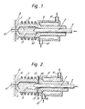
- Fig. 1 illustrates the apparatus in one of its simplest forms
- Fig. 2 illustrates an apparatus incorporating a divergent passage and a thermal barrier.
- FIG. 1 denotes a body member formed with a straight passage 2 debouching into a closed heating chamber 3 from which a discharge opening 4 leads.
- 5 denotes the coils of an induction heating apparatus surrounding the heating chamber 3 so that the induction heating effect is concentrated in material in the melting chamber and 6 denotes a water jacket surrounding the portion of the body member formed with the passage 2.
- 7 denotes a bar of moulding or casting material arranged to be forced through the passage 2 in which it is a sliding fit into the heating chamber 3.
- 8 denotes a portion of a mould having an inlet opening 9 aligned with the discharge opening 4 in the body member 1.
- 10 and 11 denote inlet and discharge passages for coolant to be fed through the jacket 6.
- the body member is in two portions lA and lB connected to one another in a plane substantially normal to the axis of the passage 2 by way of a thermal barrier 12.
- the end of the passage 2 which debouches into the heating chamber 3 is divergent towards the heating chamber as indicated at 13, the thermal barrier 12 being located at a position between the ends of the divergent portion 13,
- 14 denotes molten material from the heating chamber 3 whicn has leaked into a portion of the passage 2 between the walls of the passage and the bar 7 for a short distance from the heating chamber 3, said leakage being occasioned by the pressure in the heating chamber 3 as the bar 7 is forced into the heating chamber 3 and in the construction of Fi g .
- high injection pressures may be used without danger of leakage and without the necessity of using apparatus containing movable parts which may leak or give trouble and become corroded by the moulding or casting material since the bar of melting or casting material acts as its own pump.
Landscapes
- Engineering & Computer Science (AREA)
- Mechanical Engineering (AREA)
- Manufacturing & Machinery (AREA)
- Injection Moulding Of Plastics Or The Like (AREA)
- Reciprocating Pumps (AREA)
Applications Claiming Priority (2)
| Application Number | Priority Date | Filing Date | Title |
|---|---|---|---|
| GB838334653A GB8334653D0 (en) | 1983-12-30 | 1983-12-30 | Injection moulding and casting method |
| GB8334653 | 1983-12-30 |
Publications (2)
| Publication Number | Publication Date |
|---|---|
| EP0147243A2 true EP0147243A2 (de) | 1985-07-03 |
| EP0147243A3 EP0147243A3 (de) | 1986-12-30 |
Family
ID=10553950
Family Applications (1)
| Application Number | Title | Priority Date | Filing Date |
|---|---|---|---|
| EP84309157A Withdrawn EP0147243A3 (de) | 1983-12-30 | 1984-12-31 | Verfahren und Vorrichtung zum Spritzgiessen und Giessen |
Country Status (6)
| Country | Link |
|---|---|
| US (1) | US4591476A (de) |
| EP (1) | EP0147243A3 (de) |
| JP (1) | JPS60221161A (de) |
| BR (1) | BR8406786A (de) |
| CA (1) | CA1228464A (de) |
| GB (1) | GB8334653D0 (de) |
Cited By (3)
| Publication number | Priority date | Publication date | Assignee | Title |
|---|---|---|---|---|
| FR2720213A1 (fr) * | 1994-05-18 | 1995-11-24 | Buehler Ag Geb | Procédé et dispositifs pour chauffer des corps métalliques. |
| US5758707A (en) * | 1995-10-25 | 1998-06-02 | Buhler Ag | Method for heating metallic body to semisolid state |
| AT526810A1 (de) * | 2023-01-09 | 2024-07-15 | Engel Austria Gmbh | Aufschmelzeinheit |
Families Citing this family (7)
| Publication number | Priority date | Publication date | Assignee | Title |
|---|---|---|---|---|
| DE19724331A1 (de) * | 1997-06-10 | 1998-12-24 | Battenfeld Gmbh | Verfahren zum Plastifizieren und Einspritzen von thermoplastischer Schmelze |
| JP4175602B2 (ja) * | 2001-07-02 | 2008-11-05 | 徹一 茂木 | 鋳造用注湯装置 |
| DE60332631D1 (de) * | 2002-07-23 | 2010-07-01 | Sodick Plustech Co Ltd | Injektionsvorrichtung einer leichtmetallspritzgiessmaschine |
| JP4272413B2 (ja) * | 2002-11-18 | 2009-06-03 | 株式会社ソディックプラステック | コールドチャンバダイカスト成形機の射出装置及びその計量方法 |
| WO2004071693A1 (en) * | 2003-02-13 | 2004-08-26 | Techmire Ltd. | Die-casting machine |
| US7204774B2 (en) * | 2004-05-17 | 2007-04-17 | Emerson Electric Co. | One-piece drive pulley and belt guide |
| CN115620932A (zh) * | 2022-11-14 | 2023-01-17 | 核工业西南物理研究院 | 一种等离子体高温熔融炉出料装置及熔融炉 |
Family Cites Families (8)
| Publication number | Priority date | Publication date | Assignee | Title |
|---|---|---|---|---|
| US2689376A (en) * | 1948-07-13 | 1954-09-21 | George W Wacker | Method and apparatus for injection molding |
| US2995159A (en) * | 1957-12-23 | 1961-08-08 | United Shoe Machinery Corp | Portable plastic injection devices |
| GB1175650A (en) * | 1968-11-07 | 1969-12-23 | Standard Telephones Cables Ltd | Adhesive Applicator |
| ZA72426B (en) * | 1971-01-22 | 1973-06-27 | Bostik Ltd | Improvements in or relating to devices for dispensing molten material |
| CA1029515A (en) * | 1973-09-10 | 1978-04-18 | Douglas L. Hertel | Injection molding of rubber compounds |
| FR2364699A1 (fr) * | 1976-09-20 | 1978-04-14 | Sofragraf | Applicateur de colle thermofusible |
| DE2844932A1 (de) * | 1978-10-16 | 1980-04-30 | Hilti Ag | Vorrichtung zum schmelzen von thermoplastischen klebstoffkoerpern |
| US4464192A (en) * | 1982-05-25 | 1984-08-07 | United Technologies Corporation | Molding process for fiber reinforced glass matrix composite articles |
-
1983
- 1983-12-30 GB GB838334653A patent/GB8334653D0/en active Pending
-
1984
- 1984-12-25 JP JP59281990A patent/JPS60221161A/ja active Granted
- 1984-12-28 US US06/687,252 patent/US4591476A/en not_active Expired - Fee Related
- 1984-12-28 BR BR8406786A patent/BR8406786A/pt not_active IP Right Cessation
- 1984-12-31 CA CA000471235A patent/CA1228464A/en not_active Expired
- 1984-12-31 EP EP84309157A patent/EP0147243A3/de not_active Withdrawn
Cited By (6)
| Publication number | Priority date | Publication date | Assignee | Title |
|---|---|---|---|---|
| FR2720213A1 (fr) * | 1994-05-18 | 1995-11-24 | Buehler Ag Geb | Procédé et dispositifs pour chauffer des corps métalliques. |
| FR2725391A1 (fr) * | 1994-05-18 | 1996-04-12 | Buehler Ag Geb | Installation de moulage sous pression avec un transducteur de temps |
| FR2726495A1 (fr) * | 1994-05-18 | 1996-05-10 | Buehler Ag Geb | Installation de moulage sous pression avec un capteur de pression |
| US5758707A (en) * | 1995-10-25 | 1998-06-02 | Buhler Ag | Method for heating metallic body to semisolid state |
| AT526810A1 (de) * | 2023-01-09 | 2024-07-15 | Engel Austria Gmbh | Aufschmelzeinheit |
| AT526810B1 (de) * | 2023-01-09 | 2025-04-15 | Engel Austria Gmbh | Aufschmelzeinheit |
Also Published As
| Publication number | Publication date |
|---|---|
| CA1228464A (en) | 1987-10-27 |
| EP0147243A3 (de) | 1986-12-30 |
| GB8334653D0 (en) | 1984-02-08 |
| JPH0116591B2 (de) | 1989-03-24 |
| US4591476A (en) | 1986-05-27 |
| JPS60221161A (ja) | 1985-11-05 |
| BR8406786A (pt) | 1985-10-22 |
Similar Documents
| Publication | Publication Date | Title |
|---|---|---|
| EP1046445B1 (de) | Verfahren und Vorrichtung zum Spritzgiessen von Leichtmetall | |
| EP0117510B1 (de) | Ringenverschlusseinrichtung für Spritzgusswerkzeuge | |
| JP4119892B2 (ja) | 軽金属射出成形機の射出装置 | |
| US4591476A (en) | Injection moulding casting method | |
| US6070643A (en) | High vacuum die casting | |
| US5501266A (en) | Method and apparatus for injection molding of semi-solid metals | |
| RU2023532C1 (ru) | Способ литья под давлением методом инжекции металлического материала, имеющего дендритные свойства, и устройство для его осуществления | |
| EP0444455B1 (de) | Gekühlter Spritzgiessverteilerkanal | |
| RU2277454C2 (ru) | Инжекционное сопло для машины, предназначенной для литья под давлением материала с металлическими свойствами, и соединение сопла и литниковой втулки | |
| JPS6159219B2 (de) | ||
| US5061174A (en) | Injection molding apparatus having separate heating element in the cavity forming insert | |
| KR20030080019A (ko) | 배럴 조립체 | |
| CA2453397A1 (en) | Method and apparatus for thixotropic molding of semisolid alloys | |
| CA2628504A1 (en) | Device for casting | |
| JP3477126B2 (ja) | ホットランナユニット内の金属原料の排出方法 | |
| EP0106980A1 (de) | Verschlussdüse zum Spritzgiessen | |
| US7497680B2 (en) | Conduit connection of molding system | |
| US12042852B2 (en) | Apparatus for creating at least one metal component and method therefor | |
| US6923244B2 (en) | Pouring apparatus for castings | |
| EP2106867B1 (de) | Gießvorrichtung | |
| JP3258617B2 (ja) | 金属材料の射出装置 | |
| US7575428B2 (en) | Molding system including body overlapping and sealing conduits, amongst other things | |
| JP2007061880A (ja) | 射出成形装置 | |
| KR840001143B1 (ko) | 다이캐스팅 장치 | |
| JP2004255381A (ja) | 溶解金属用密封装置 |
Legal Events
| Date | Code | Title | Description |
|---|---|---|---|
| PUAI | Public reference made under article 153(3) epc to a published international application that has entered the european phase |
Free format text: ORIGINAL CODE: 0009012 |
|
| AK | Designated contracting states |
Designated state(s): AT BE CH DE FR GB IT LI NL SE |
|
| PUAL | Search report despatched |
Free format text: ORIGINAL CODE: 0009013 |
|
| AK | Designated contracting states |
Kind code of ref document: A3 Designated state(s): AT BE CH DE FR GB IT LI NL SE |
|
| STAA | Information on the status of an ep patent application or granted ep patent |
Free format text: STATUS: THE APPLICATION IS DEEMED TO BE WITHDRAWN |
|
| 18D | Application deemed to be withdrawn |
Effective date: 19870101 |
|
| R18D | Application deemed to be withdrawn (corrected) |
Effective date: 19870102 |
|
| RIN1 | Information on inventor provided before grant (corrected) |
Inventor name: GREENWOOD, DAVID Inventor name: SMITH, ROGER JOHN |