EP0147144A2 - Anordnung zur Steigrohrführung für "offshore"-Bohrplattform - Google Patents
Anordnung zur Steigrohrführung für "offshore"-Bohrplattform Download PDFInfo
- Publication number
- EP0147144A2 EP0147144A2 EP84308752A EP84308752A EP0147144A2 EP 0147144 A2 EP0147144 A2 EP 0147144A2 EP 84308752 A EP84308752 A EP 84308752A EP 84308752 A EP84308752 A EP 84308752A EP 0147144 A2 EP0147144 A2 EP 0147144A2
- Authority
- EP
- European Patent Office
- Prior art keywords
- pile
- center post
- frame structure
- center
- conductors
- Prior art date
- Legal status (The legal status is an assumption and is not a legal conclusion. Google has not performed a legal analysis and makes no representation as to the accuracy of the status listed.)
- Withdrawn
Links
Images

Classifications
-
- E—FIXED CONSTRUCTIONS
- E02—HYDRAULIC ENGINEERING; FOUNDATIONS; SOIL SHIFTING
- E02B—HYDRAULIC ENGINEERING
- E02B17/00—Artificial islands mounted on piles or like supports, e.g. platforms on raisable legs or offshore constructions; Construction methods therefor
-
- E—FIXED CONSTRUCTIONS
- E21—EARTH OR ROCK DRILLING; MINING
- E21B—EARTH OR ROCK DRILLING; OBTAINING OIL, GAS, WATER, SOLUBLE OR MELTABLE MATERIALS OR A SLURRY OF MINERALS FROM WELLS
- E21B17/00—Drilling rods or pipes; Flexible drill strings; Kellies; Drill collars; Sucker rods; Cables; Casings; Tubings
- E21B17/01—Risers
-
- E—FIXED CONSTRUCTIONS
- E21—EARTH OR ROCK DRILLING; MINING
- E21B—EARTH OR ROCK DRILLING; OBTAINING OIL, GAS, WATER, SOLUBLE OR MELTABLE MATERIALS OR A SLURRY OF MINERALS FROM WELLS
- E21B19/00—Handling rods, casings, tubes or the like outside the borehole, e.g. in the derrick; Apparatus for feeding the rods or cables
- E21B19/002—Handling rods, casings, tubes or the like outside the borehole, e.g. in the derrick; Apparatus for feeding the rods or cables specially adapted for underwater drilling
-
- E—FIXED CONSTRUCTIONS
- E21—EARTH OR ROCK DRILLING; MINING
- E21B—EARTH OR ROCK DRILLING; OBTAINING OIL, GAS, WATER, SOLUBLE OR MELTABLE MATERIALS OR A SLURRY OF MINERALS FROM WELLS
- E21B7/00—Special methods or apparatus for drilling
- E21B7/04—Directional drilling
- E21B7/043—Directional drilling for underwater installations
-
- E—FIXED CONSTRUCTIONS
- E02—HYDRAULIC ENGINEERING; FOUNDATIONS; SOIL SHIFTING
- E02B—HYDRAULIC ENGINEERING
- E02B17/00—Artificial islands mounted on piles or like supports, e.g. platforms on raisable legs or offshore constructions; Construction methods therefor
- E02B2017/0095—Connections of subsea risers, piping or wiring with the offshore structure
Definitions
- This invention relates to conductor guide arrangements for offshore well or drilling platforms and to methods of asembling such arrangements.
- the drilling of wells at offshore locations using offshore platforms is accomplished through large diameter steel pipes, called conductors, which are driven into the soil at the sea bed through guides connected to a jacket and deck structure of the offshore platform.
- the conductors extend upwardly through a pile of the platform jacket.
- the jacket is a tubular steel framework that serves as a pile template and extends from the sea bed to a few feet above the water level.
- Steel superstructure of the platform including decks are connected to the piling or the jacket to support the drilling and production facilities.
- the piling consists of steel tubes which secure the platform to the sea bed and penetrate the soil up to 90 to 180 m (300 to 600 feet).
- the platform components such as the jacket, one or more decks, and piling, are built on land at fabrication yards as completely as possible in order to minimize the far more expensive offshore construction at the offshore site.
- Conductor guides for positioning and guiding the conductors are framed at various elevations within, the jacket and decks to provide support for the conductors such that the usual effects of environment such as waves, winds, current and the like can be safely withstood by the conductors and to maintain conductor alignment.
- the first system which is more common and older, consists of guides which are rigidly connected to the jacket and deck framework. The conductors are placed through these guides.
- This type of system generally Includes three kinds of conductor guide assemblies.
- the first kind are those within the horizontal framework levels of the jacket and typically consist of vertical guides made out of steel tubes welded to the horizontal jacket tubular members.
- the other types are located In the upper and lower deck levels.
- the lower deck level guides are similar to those of the jacket except that they are rigidly connected to the deck floor beams. These guides are located in line with the jacket guides.
- the upper deck level assembly consists of a grid of beams bolted to the permanent upper deck beams supporting removable hatches which line up with the conductor guides in the lower deck. Access is provided to the lower deck level, which Is typically the conductor termination level, by removing the hatches.
- the second type of arrangement which has recently been utilized in areas of extreme environmental loading such as mud slide zones, consists of jacket conductor guides positioned inside a large diameter pile which has previously been driven through a jacket sleeve.
- the pile protects the conductors from environmental loading.
- the typical jacket conductor assembly consists of a series of horizontal guide frames connected to a central post and supported by the pile at its top. Additional guide assemblies similar to those described with respect to the first type of arrangement are provided in the decks of the platform. Because the jacket conductor guide assembly must be erected offshore after the jacket and piling are installed, it is required that the conductor guides for the deck sections be built offshore to conform to the orientation of the conductor guides in the pile.
- the jacket assembly Due to its length, the jacket assembly is built on land In several sections which are subsequently installed and welded together offshore.
- temporary beams are required for supporting the structure as it is assembled and Installed at the offshore site.
- the handling of such beam supports on the top of the pile for large guides is time consuming and sometimes requires the use of cranes or similar equipment.
- the present invention provides a conductor guide assembly and method of assembling the same for a plurality of conductors for an offshore drilling or well platform.
- a first conductor guide means is disposed in and supported by and on the interior pile which extends through the jacket from below the sea bed to above the water level over the sea bed.
- a second guide means is associated with at least one lower deck of the platform that is connected to the jacket.
- a plurality of passages are defined in the second guide means through which the conductors extend and are positioned with respect to the lower deck.
- the second guide means is temporarily connected such as by spot welding to the lower deck at the land based fabrication facility. It can thus be detached temporarily so that it can be rotated to align the passages with the plurality of conductors or at least the positions for the conductors in the interior pile. Thereafter, the second guide means is permanently connected, usually by welding, to the lower deck.
- a third guide means is provided on the upper deck which also has a plurality of passages for permitting access to the plurality of conductors.
- the third guide means is supported by beams in the upper deck which permit limited rotation of the third guide means to align passages thereof with the passages of the second guide means.
- the first guide means comprises a plurality of frame arrangements which are each equipped with removable bolt-on units that can be used to support the unfinished first guide means as sections thereof are assembled above the interior pile.
- the bolt-on units can then be removed to drop the first guide means, section by section, into the interior pile as additional sections are added.
- the invention also provides a conductor guide arrangement for conductors of an offshore well platform having a jacket, the arrangement comprising:
- the invention provides a method of assembling a conductor guide arrangement for a plurality of conductors of an offshore well platform including a jacket, the method comprising:
- a preferred embodiment of the invention described hereinbelow provides a conductor guide arrangement which facilitates the positioning and guiding of conductors in an offshore platform so that the amount of construction work required at the offshore site is minimized.
- the preferred conductor guide arrangement is simple in design, rugged in construction, and economical to manufacture.
- the preferred embodiment also provides a method of assembling a conductor guide arrangement wherein the burdensome requirement of using temporary beams to support the structure is eliminated.
- Fig. 1 shows an offshore drilling platform which is connected to a sea bed 1 and extends up to and above a water level 3 above the sea bed.
- the platform includes a jacket 2 which is a framework made of steel tubing and generally includes four corner piles 5 which are sunk into the soil of the sea bed or otherwise anchored to the sea bed.
- a pile 4 extends through the interior of the jacket 2. This is a tubular structure that is typically between about 2.4 and 4.6 m (8 and 15 feet) in diameter and may be inserted in a sleeve which has been fabricated -and installed in the jacket ashore. The pile 4 may be driven into the sea bed for up to 90 to 180 m (300 to 600 feet).
- the interior pile 4 extends to a metre or so (a few feet) above the water level 3 and contains a plurality of conductors 10 through which access can be had to the sea bed and below.
- the conductors each have a diameter of typically between about 510 and 760 mm (20 and 30 inches) and are positioned and guided in the interior pile 4 by first guide means generally designated 20 to be described in detail hereinunder.
- the platform is provided with one or more lower decks 6 and at least one upper deck 8.
- the decks 6 and 8 are connected to the jacket 2 through supports 7 and 9 respectively.
- Second guide means generally designated 30 are connected to the lower deck 6 and define passages for the conductors 10.
- Third guide means generally designated 40 are connected to the upper deck 8 and also define passages which are aligned with the passages of the second guide means 30 and provide access to the tops of the conductors.
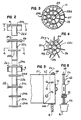
- the first guide means,20 is made up of a plurality of sub-assemblies which each include a vertical center post 22a to 22d.
- Sections 22a, 22b, and 22c which are designed to be received entirely within the interior pile 4, each include one or more but preferably at least two steel frame structures 24a to 24c for section 22a, 24d and 24e for section 22b, and 24f and 24g for section 22c.
- the upper structure 24c, 24e, and 24g of each section 22a, 22b, and 22c respectively is provided with a plurality of removable support brackets 26 which establish an effective outer diameter for the structures which is greater than the diameter of the interior pile 4.
- the steel frame structure 24h at the top of the top section 22d has an outer diameter (without any support bracket) which is greater than the diameter of the interior pile 4 so that it can be permanently supported on top of the interior pile 4 to support and suspend the remainder of the second guide means thereunder.
- the uppermost steel frame 24h includes a plurality of steel plate spokes 27 extending radially outwardly of the center post 22d, an intermediate ring 28 and outer ring 31 which are also made of steel plate, and an upper plate 29 having apertures therein for receiving a plurality of conductors 10.
- a steel frame structure 24f which is typical of all the frame structures except for the top frame structure 24h, comprises a plurality of steel plate spokes 57 extending radially outwardly of the center post 22c, a conductor engaging band 56, and a cover plate 55.
- cover plate 55 includes semicircular recess 58 as well as openings 60 aligned with similar recesses 58 and openings 60 in other cover plates for positioning a plurality of the conductors 10 at selected locations.
- plate 28 of frame structure 24h provides aligned apertures for positioning of the conductors in the same pattern.
- the center posts 22a to 22d may also serve as conductors.
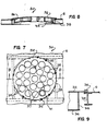
- each support bracket 26 includes a pair of vertical plates 62 spaced apart to minimize the bracket weight while providing adequate support. Plates 62 have aligned apertures 64 therethrough and are connected together by a bottom plate . 66, the upper plate 68 of a lifting eye, which lifting eye hook point is aligned with the center of gravity of the bracket for stability during lifting thereof, and a side plate 70 of another lifting eye. Apertures 64 are aligned with apertures through the end of spokes 57 to receive bolts, one of which is shown at 72. As shown in Fig. 5, the support bracket 26 increases the effective outer diameter of the respective frame structure 24c, 24e and 24g so that bottom plate 66 rests on the top of interior pile 4.
- the first or lowest section with vertical center post 22a is lowered into the open top end of pile 4 until the bolted on support brackets 26 rest on the top edge of the pile as shown in Fig. 5.
- the next section with vertical center post 22b is then lowered and stabbed to the lower section. After this section is rotated to a preferably keyed position to align its conductor openings 58 and 60 with those of other sections, the two center posts 22a and 22b are then welded together.
- the second guide means 30 includes a cover plate 32 which is cambered as shown in Fig. 8 and includes a plurality of aligned openings 39 which define passages for receiving and positioning the conductors 10.
- Plate 32 is of such a diameter that the outer periphery of plate 32 can overlie an opening in the upper deck and rest on the upper deck portions which lie adjacent to and define such opening. It is preferred that plate 32 rest on a plurality of upper deck beams 38 to ensure adequate support.
- the conductor passages are not symmetrically positioned.
- the conductor openings may be provided therein at the onshore site but the conductor openings must align with the conductor openings of the first guide means 20 when the second guide means 30 is installed.
- the plate 32 is provided to be circular to rotate about its center over beams 38, and small lengths of angle iron 35, which are welded to beams 38, extend along and are spaced about the cover plate circumference and extend over the periphery of plate 32 to maintain its center position.
- Three lifting eyes 37 are welded to cover plate 32 for lifting the plate.
- the second guide means 30 is also provided with a circular and similarly cambered and apertured lower plate 34 which has a diameter which is less than the cover plate diameter to fit within the space of the lower deck opening and between the beams 38, as shown in Fig. 8. Openings 39 may be outfitted with suitable sleeves as illustrated at 41 in Fig. 7 for receiving the conductors.
- the cover and lower plates 32 and 34 respectively are spaced apart and connected together by a circular ring 36 welded to the plates 32 and 34 and sleeves 41 to further increase the rigidity and resistance to deflection thereof.
- plate 32 is spot welded into place at short weld locations. At the offshore site, these weld locations are torch cut so that plate 32 with its connected ring 36 and lower plate 34, can be rotated to align the passages defined by openings 39 with the passages already defined in the first guide means of the interior pile 4. Conductors 10 can thus be slipped through openings 39 and into their positioning passages in the first guide means.
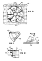
- the upper deck is equipped with third guide means 40 having a center hub 42 with radially extending steel beams 44 configured as the spokes of a wheel and overlying an opening in the upper deck.
- beams 44 define sector shaped generally triangular areas which may each provide access to the tops of a plurality of conductors 10 which are actually below the upper deck as viewed from Fig. 10.
- Each of these areas may be covered by a hatch 46, shown in Fig. 11, having its own frame structure 48.
- Seat plates 47 are bolted or welded to beams 44 for supporting the hatches 46 which can be bolted to these seat plates for easy removal and access to the tops of the conductors 10.
- the upper deck is provided with deck beams 50 forming seats on which outer edges of beams 44 can rest and permitting rotation of the circular third guide means 40 about the hub 42 to align the passages with the configuration of conductors. After alignment, the outer edges of beams 44 can be bolted or welded to beams 30.
- the beams 44 may be either welded or bolted to the hub 42 and beams 50, it is preferred that some beams 44 be bolted to allow their removal so that openings may be provided which are large enough to pass large apparatus such as blowout preventers therethrough, and that others of the beams 44 be welded to provided support without the danger of the third guide means falling to a lower deck if all of the beams were unbolted.
- alternate beams may be welded, and alternate beams may be bolted.
Landscapes
- Engineering & Computer Science (AREA)
- Geology (AREA)
- Mining & Mineral Resources (AREA)
- Life Sciences & Earth Sciences (AREA)
- General Life Sciences & Earth Sciences (AREA)
- Fluid Mechanics (AREA)
- Environmental & Geological Engineering (AREA)
- Physics & Mathematics (AREA)
- Mechanical Engineering (AREA)
- Geochemistry & Mineralogy (AREA)
- General Engineering & Computer Science (AREA)
- Civil Engineering (AREA)
- Structural Engineering (AREA)
- Foundations (AREA)
- Earth Drilling (AREA)
- Placing Or Removing Of Piles Or Sheet Piles, Or Accessories Thereof (AREA)
Applications Claiming Priority (2)
| Application Number | Priority Date | Filing Date | Title |
|---|---|---|---|
| US06/562,546 US4561802A (en) | 1983-12-19 | 1983-12-19 | Assembly of conductor guides for offshore drilling platform |
| US562546 | 1983-12-19 |
Publications (2)
| Publication Number | Publication Date |
|---|---|
| EP0147144A2 true EP0147144A2 (de) | 1985-07-03 |
| EP0147144A3 EP0147144A3 (de) | 1985-11-27 |
Family
ID=24246713
Family Applications (1)
| Application Number | Title | Priority Date | Filing Date |
|---|---|---|---|
| EP84308752A Withdrawn EP0147144A3 (de) | 1983-12-19 | 1984-12-14 | Anordnung zur Steigrohrführung für "offshore"-Bohrplattform |
Country Status (8)
| Country | Link |
|---|---|
| US (1) | US4561802A (de) |
| EP (1) | EP0147144A3 (de) |
| JP (1) | JPS6175193A (de) |
| KR (1) | KR890002803B1 (de) |
| AU (1) | AU3657984A (de) |
| BR (1) | BR8406493A (de) |
| CA (1) | CA1215551A (de) |
| ES (2) | ES8604669A1 (de) |
Cited By (5)
| Publication number | Priority date | Publication date | Assignee | Title |
|---|---|---|---|---|
| GB2292164A (en) * | 1994-08-11 | 1996-02-14 | Mcdermott Int Inc | Fixed offshore platform structures |
| WO1999047784A1 (en) * | 1998-03-14 | 1999-09-23 | Shell Internationale Research Maatschappij B.V. | Supporting frame for risers |
| CN103953061A (zh) * | 2014-05-19 | 2014-07-30 | 广东明阳风电产业集团有限公司 | 一种海上风电导管架基础结构 |
| CN112709253A (zh) * | 2020-12-25 | 2021-04-27 | 烟台铁中宝钢铁加工有限公司 | 导管架及导管架建造方法 |
| CN118917028A (zh) * | 2024-09-26 | 2024-11-08 | 长江三峡集团实业发展(北京)有限公司 | 一种基于细观模型的导管架多尺度建模方法 |
Families Citing this family (15)
| Publication number | Priority date | Publication date | Assignee | Title |
|---|---|---|---|---|
| US4932811A (en) * | 1989-06-08 | 1990-06-12 | Robert Folding | Well head conductor and/or caisson support system |
| US5527136A (en) * | 1994-07-05 | 1996-06-18 | Halliburton Company | Mono-tripod platform |
| WO1997009508A1 (en) * | 1995-09-01 | 1997-03-13 | Chevron U.S.A. Inc. | Method and apparatus for drilling multiple wells from a low load platform |
| US5865260A (en) * | 1995-09-01 | 1999-02-02 | Chevron U.S.A. Inc. | Method and apparatus for drilling multiple wells from a platform |
| US6299385B1 (en) * | 1999-08-04 | 2001-10-09 | Paragon Engineering Services Incorporated | Mini-jacket and method for installation using caisson |
| US7967065B2 (en) * | 2007-11-30 | 2011-06-28 | Frank's Casing Crew And Rental Tools, Inc. | Caisson system |
| US9089928B2 (en) | 2008-08-20 | 2015-07-28 | Foro Energy, Inc. | Laser systems and methods for the removal of structures |
| US11028549B2 (en) | 2015-10-29 | 2021-06-08 | Maersk Drilling A/S | Offshore drilling and a configurable support structure for the same |
| JP6216008B1 (ja) * | 2016-07-12 | 2017-10-18 | 東急建設株式会社 | フットパイル頭部金具およびそれを用いた、支保工とフットパイルの接続方法 |
| CN107100155A (zh) * | 2017-05-25 | 2017-08-29 | 中能电力科技开发有限公司 | 一种用于海上风电施工的整体式作业平台及该平台的施工方法 |
| US12060271B2 (en) | 2020-07-09 | 2024-08-13 | University Of Hawai'i | Continuous production of nanoforests |
| US12225701B1 (en) | 2021-03-16 | 2025-02-11 | Goodman Technologies LLC | Electromagnetic and radiation shielding using nanoforests |
| CN113898318B (zh) * | 2021-10-12 | 2022-12-09 | 北部湾大学 | 一种一体式简易井口平台 |
| CN115125906A (zh) * | 2022-07-11 | 2022-09-30 | 中交第一航务工程局有限公司 | 导管架结构的码头及组合码头 |
| CN116255100B (zh) * | 2023-04-27 | 2023-09-12 | 山东爱特机电技术有限责任公司 | 一种超级电容储能的电动修井机 |
Family Cites Families (8)
| Publication number | Priority date | Publication date | Assignee | Title |
|---|---|---|---|---|
| US2475888A (en) * | 1947-09-19 | 1949-07-12 | Allen S Hackett | Pier for offshore drilling rigs |
| US3186180A (en) * | 1963-04-25 | 1965-06-01 | Shell Oil Co | Offshore well drilling and oil storage platform |
| US3572041A (en) * | 1968-09-18 | 1971-03-23 | Shell Oil Co | Spar-type floating production facility |
| US3602319A (en) * | 1969-09-26 | 1971-08-31 | Global Marine Inc | Structure with varying cross-sectional moment of inertia |
| US3991581A (en) * | 1975-06-02 | 1976-11-16 | Brown & Root, Inc. | Method and apparatus for handling piling and anchoring an offshore tower |
| US4027734A (en) * | 1975-12-11 | 1977-06-07 | Hebert & Co., Inc. Gurtler | Deviated conductor driving system |
| US4050731A (en) * | 1976-01-26 | 1977-09-27 | Lynes, Inc. | Shifting apparatus |
| US4100754A (en) * | 1976-07-28 | 1978-07-18 | Rudolf Vogel | Method and apparatus for installing pipes in off-shore locations |
-
1983
- 1983-12-19 US US06/562,546 patent/US4561802A/en not_active Expired - Fee Related
-
1984
- 1984-12-12 AU AU36579/84A patent/AU3657984A/en not_active Abandoned
- 1984-12-13 KR KR1019840007916A patent/KR890002803B1/ko not_active Expired
- 1984-12-14 EP EP84308752A patent/EP0147144A3/de not_active Withdrawn
- 1984-12-14 JP JP59263114A patent/JPS6175193A/ja active Granted
- 1984-12-17 BR BR8406493A patent/BR8406493A/pt unknown
- 1984-12-17 CA CA000470310A patent/CA1215551A/en not_active Expired
- 1984-12-18 ES ES538723A patent/ES8604669A1/es not_active Expired
-
1985
- 1985-10-18 ES ES548003A patent/ES8609578A1/es not_active Expired
Cited By (9)
| Publication number | Priority date | Publication date | Assignee | Title |
|---|---|---|---|---|
| GB2292164A (en) * | 1994-08-11 | 1996-02-14 | Mcdermott Int Inc | Fixed offshore platform structures |
| GB2292164B (en) * | 1994-08-11 | 1997-08-27 | Mcdermott Int Inc | Fixed offshore platform structures |
| WO1999047784A1 (en) * | 1998-03-14 | 1999-09-23 | Shell Internationale Research Maatschappij B.V. | Supporting frame for risers |
| GB2351749A (en) * | 1998-03-14 | 2001-01-10 | Shell Int Research | Supporting frame for risers |
| GB2351749B (en) * | 1998-03-14 | 2002-06-12 | Shell Int Research | Conductor supported pulltube bundle |
| CN103953061A (zh) * | 2014-05-19 | 2014-07-30 | 广东明阳风电产业集团有限公司 | 一种海上风电导管架基础结构 |
| CN103953061B (zh) * | 2014-05-19 | 2015-11-11 | 广东明阳风电产业集团有限公司 | 一种海上风电导管架基础结构 |
| CN112709253A (zh) * | 2020-12-25 | 2021-04-27 | 烟台铁中宝钢铁加工有限公司 | 导管架及导管架建造方法 |
| CN118917028A (zh) * | 2024-09-26 | 2024-11-08 | 长江三峡集团实业发展(北京)有限公司 | 一种基于细观模型的导管架多尺度建模方法 |
Also Published As
| Publication number | Publication date |
|---|---|
| US4561802A (en) | 1985-12-31 |
| EP0147144A3 (de) | 1985-11-27 |
| KR890002803B1 (ko) | 1989-07-31 |
| ES8609578A1 (es) | 1986-09-01 |
| KR850004432A (ko) | 1985-07-15 |
| CA1215551A (en) | 1986-12-23 |
| AU3657984A (en) | 1985-06-27 |
| BR8406493A (pt) | 1985-10-15 |
| ES538723A0 (es) | 1986-02-01 |
| JPS6326233B2 (de) | 1988-05-28 |
| ES8604669A1 (es) | 1986-02-01 |
| JPS6175193A (ja) | 1986-04-17 |
| ES548003A0 (es) | 1986-09-01 |
Similar Documents
| Publication | Publication Date | Title |
|---|---|---|
| US4561802A (en) | Assembly of conductor guides for offshore drilling platform | |
| US4607983A (en) | Method of constructing an offshore tower structure | |
| AU744392B2 (en) | Scaffoldless tank erection method | |
| US4932811A (en) | Well head conductor and/or caisson support system | |
| US2422168A (en) | Marine tower and method of placing same | |
| US2304354A (en) | Method of increasing the height of storage tanks | |
| AU2012201011A1 (en) | Device for manufacturing a foundation for a mass located at height, associated method and assembly of the device and a jack-up platform | |
| EP0306145B1 (de) | Caisson-Plattformturm und dessen Aufstellungsverfahren | |
| CA2268994C (en) | Method for fabricating an excavator base | |
| US2946566A (en) | Subaqueous drilling apparatus | |
| US4561803A (en) | Conductor guide system for offshore drilling platform | |
| IE45199B1 (en) | Method of fabrication of off-shore structures and off-shore structures made according to this method | |
| EP0088586A2 (de) | Offshore-Turmkonstruktion und Verfahren zum Errichten und Installieren | |
| US3668876A (en) | Offshore tower apparatus and method | |
| JP7602578B1 (ja) | ジャケット構造体システム、ギャングウェイ架渡し方法、及び、トランジションピースシステム | |
| US4187038A (en) | Equipment for extracting oil or gas from under the sea bed and method of installing such equipment | |
| CA1238199A (en) | Conductor guide system for offshore drilling platform | |
| CA2479412C (en) | Method of fabricating a tall multi-stage work piece | |
| US5380130A (en) | Preinstalled adjustable conductor guide | |
| US4534677A (en) | Secondary capping beams for offshore drilling platforms | |
| CN85106162A (zh) | 海上钻井平台的导管导向装置 | |
| CN85106164A (zh) | 海上钻井平台的导管导向装置 | |
| US4487526A (en) | Method of and structure for erecting an artificial island | |
| US3107495A (en) | Method of erecting an offshore structure | |
| GB2139570A (en) | Jack-up rig |
Legal Events
| Date | Code | Title | Description |
|---|---|---|---|
| PUAI | Public reference made under article 153(3) epc to a published international application that has entered the european phase |
Free format text: ORIGINAL CODE: 0009012 |
|
| AK | Designated contracting states |
Designated state(s): AT BE CH DE FR GB IT LI LU NL SE |
|
| PUAL | Search report despatched |
Free format text: ORIGINAL CODE: 0009013 |
|
| AK | Designated contracting states |
Designated state(s): AT BE CH DE FR GB IT LI LU NL SE |
|
| 17P | Request for examination filed |
Effective date: 19860502 |
|
| 17Q | First examination report despatched |
Effective date: 19870825 |
|
| STAA | Information on the status of an ep patent application or granted ep patent |
Free format text: STATUS: THE APPLICATION IS DEEMED TO BE WITHDRAWN |
|
| 18D | Application deemed to be withdrawn |
Effective date: 19880823 |
|
| RIN1 | Information on inventor provided before grant (corrected) |
Inventor name: CAMPO, JUAN J. |