EP0147076A2 - Electrical terminal having a receptacle contact section of low insertion force and terminating section therefor - Google Patents
Electrical terminal having a receptacle contact section of low insertion force and terminating section therefor Download PDFInfo
- Publication number
- EP0147076A2 EP0147076A2 EP84308254A EP84308254A EP0147076A2 EP 0147076 A2 EP0147076 A2 EP 0147076A2 EP 84308254 A EP84308254 A EP 84308254A EP 84308254 A EP84308254 A EP 84308254A EP 0147076 A2 EP0147076 A2 EP 0147076A2
- Authority
- EP
- European Patent Office
- Prior art keywords
- contact
- electrical terminal
- section
- matable
- contact section
- Prior art date
- Legal status (The legal status is an assumption and is not a legal conclusion. Google has not performed a legal analysis and makes no representation as to the accuracy of the status listed.)
- Granted
Links
- 230000037431 insertion Effects 0.000 title abstract description 33
- 238000003780 insertion Methods 0.000 title abstract description 33
- 239000011324 bead Substances 0.000 description 3
- PCHJSUWPFVWCPO-UHFFFAOYSA-N gold Chemical compound [Au] PCHJSUWPFVWCPO-UHFFFAOYSA-N 0.000 description 2
- 239000010931 gold Substances 0.000 description 2
- 229910052737 gold Inorganic materials 0.000 description 2
- 239000002184 metal Substances 0.000 description 2
- 229910052751 metal Inorganic materials 0.000 description 2
- 238000005452 bending Methods 0.000 description 1
- 239000004020 conductor Substances 0.000 description 1
- 238000010276 construction Methods 0.000 description 1
- 230000000994 depressogenic effect Effects 0.000 description 1
- 238000006073 displacement reaction Methods 0.000 description 1
- 230000000717 retained effect Effects 0.000 description 1
- 239000013589 supplement Substances 0.000 description 1
Images

Classifications
-
- H—ELECTRICITY
- H01—ELECTRIC ELEMENTS
- H01R—ELECTRICALLY-CONDUCTIVE CONNECTIONS; STRUCTURAL ASSOCIATIONS OF A PLURALITY OF MUTUALLY-INSULATED ELECTRICAL CONNECTING ELEMENTS; COUPLING DEVICES; CURRENT COLLECTORS
- H01R13/00—Details of coupling devices of the kinds covered by groups H01R12/70 or H01R24/00 - H01R33/00
- H01R13/02—Contact members
- H01R13/193—Means for increasing contact pressure at the end of engagement of coupling part, e.g. zero insertion force or no friction
-
- H—ELECTRICITY
- H01—ELECTRIC ELEMENTS
- H01R—ELECTRICALLY-CONDUCTIVE CONNECTIONS; STRUCTURAL ASSOCIATIONS OF A PLURALITY OF MUTUALLY-INSULATED ELECTRICAL CONNECTING ELEMENTS; COUPLING DEVICES; CURRENT COLLECTORS
- H01R13/00—Details of coupling devices of the kinds covered by groups H01R12/70 or H01R24/00 - H01R33/00
- H01R13/02—Contact members
- H01R13/15—Pins, blades or sockets having separate spring member for producing or increasing contact pressure
- H01R13/187—Pins, blades or sockets having separate spring member for producing or increasing contact pressure with spring member in the socket
Definitions
- the invention relates to an electrical terminal and more particularly to an electrical terminal having a receptacle contact section of low insertion force.
- Electrical terminals have a receptacle contact section including a contact-receiving area for receiving a matable contact which includes a resilient contact member and a spring-assist member which are part of the receptacle contact section.
- These electrical terminals include a main resilient contact member which extends backward and into the contact-receiving area from the front end of the receptacle contact section and which is of a relatively long length and a spring-assist member extending from a rear portion of the receptacle contact section and which is of a relatively short length.
- the spring-assist member supports the main resilient contact member arm so as to supplement a spring force of the main resilient contact member so that a high contact pressure can be obtained when the receptacle contact section mates with a matable contact.
- the main resilient contact member is supported at its central portion by a free end of the spring-assist member which is relatively rigid, the effective arm length of the main resilient contact member, which serves as a cantilever, is shortened and, as a result of this, the main resilient contact member is rigid so that the insertion force of the matable contact into the receptacle contact section is substantially increased.
- the receptacle contact section is plated with gold, the gold is worn through after a few engagements and disengagements so that the useful electrical life of the contact section is shortened.
- a large force is needed to mate and release the matable connectors.
- the present invention of an electrical terminal having a receptacle contact section of low insertion force overcomes the above-mentioned problems.
- the object of the present invention is to provide an electrical terminal having a receptacle contact section into which a matable contact is inserted with a low insertion force and which ensures a reliable and high contact pressure with the matable contact when the matable contact is fully inserted into the contact section.
- an electrical terminal comprises a receptacle contact section having cantilever contact members extending from a bottom wall at forward and rear ends of the contact section, the contact members extend toward an upper wall and free ends of the contact members overlap and are spaced from each other so that, upon initial insertion of a matable contact into the contact section, a low insertion force is encountered and the insertion force increases gradually in proportion to the depth of insertion of the matable contact due to engagement between the overlapping free ends of the contact members so that a high contact pressure is obtained at the complete insertion of the matable contact in the receptacle contact section.
- a wire-terminating section of an electrical terminal comprises parallel plates spaced from each other and connected together by bights, wire-receiving slots in the plates and an extension of one of the plates engages the other of the plates and is disposed adjacent a lance in the other plate so that an insertion member can engage the extension between the bights and force the terminal into a terminal-receiving cavity of a housing.
- the electrical terminal 1 is made from a metal sheet having desirable conductive and spring characteristics by stamping and folding a stamped blank along lines 31-38 shown in Figure 5.
- Electrical terminal 1 has a receptacle contact section 3, the transverse cross-section of which is of a rectangular shape, and which has a contact-receiving area 4 for receiving therein a matable contact 30 having a tab configuration.
- Receptacle contact section 3 includes a resilient contact member 9 which is bent at a front end of the contact section 3 along folding line 35 ( Figure 5) and which is integral with a bottom wall 5.
- Resilient contact member 9 extends backward within contact-receiving area 4 in a direction away from bottom wall 5 as a cantilever contact member and provides a contact surface 9b for electrical engagement with matable contact 30, at the forward portion in a longitudinal direction thereof.
- An arcuate free end 9a of contact member 9 is positioned at the longitudinal central portion of contact-receiving area 4 with a gap h between an upper wall 6 and free end 9a. Gap h is less than a thickness t of matable contact 30 to be inserted between wall 6 and contact member 9.
- Spring-assist member 10 is formed out of bottom wall 5 by stamping therefrom and extends forward within contact-receiving area 4 from a rear portion of bottom wall 5 and in a direction away from bottom wall 5.
- a free end 10a of spring-assist member 10 is arcuate-shaped and is positioned adjacent arcuate free end 9a of contact member 9. Both members 9, 10 are substantially the same length, and free ends 9a, 10a are normally spaced apart by gap H.
- Bottom wall 5 has a projection 11 for engagement with a shoulder formed in a terminal-receiving cavity of an insulating housing (not shown) so that terminal 1 is retained in the housing.
- Contact section 3 has at the inner surface of upper wall 6 two inwardly-projecting beads 12 which extend in the longitudinal direction of upper wall 6. Inwardly-projecting beads 12 provide a contact surface for matable contact 30 to move along and they serve to reduce the frictional resistance of contact 30 when it is inserted in contact-receiving area 4.
- Terminal 1 has an extension 13 which extends backward as part of bottom wall 5 and provides a wire connecting section 14 which is formed by bending along folding lines 36-38 ( Figure 5).
- the wire connecting section 14 includes a pair of parallel plates 15, 16 which are spaced from each other.
- Each of plates 15, 16 has wire-receiving slots 17, 18 and plates 15, 16 are interconnected by bights 19, 20.
- a plate 21 integral with and as an extension of plate 15 extends toward plate 16.
- a free end of the plate 21 abuts plate 16 and engages a lance 22 extending outwardly from extension 13.
- Lance 22 serves to prevent plate 21 from being deformed in the direction of arrow A in Figure 2 when terminal 1 is inserted into the terminal-receiving cavity of the housing by pressing against plate 21 with an insertion member (not shown) which is inserted between bights 19, 20. Insulated electrical conductors (now shown) are electrically and mechanically terminated in wire-receiving slots 17, 18 in a known manner.
- matable contact 30 When matable contact 30 is inserted into contact-receiving area 4 of contact section 3, matable contact 30 engages resilient contact member 9, as shown in Figure 3, and presses the contact member 9 toward bottom wall 5. In this initial inserting position of the contact 30, the contact 30 receives only the spring force of resilient contact member 9 so that the insertion force is small. Contact 30 is then further inserted as shown in Figure 4, and resilient contact member 9 is further depressed so that its arcuate free end 9a engages free end 10a of spring-assist member 10 and presses member 10 toward bottom wall 5. In this complete insertion position of the contact 30 between beads 12 and member 9, contact 30 receives the combined spring force of resilient contact member 9 and spring-assist member 10 so that a high contact pressure can be obtained.
- the construction is such that the spring force of the resilient contact member only is applied to the matable contact in the initial insertion position of the matable contact in the contact-receiving area of a receptacle contact section of an electrical terminal, and the combined spring force of the resilient contact member and the spring-assist member is applied thereto at the complete insertion position of the matable contact within the contact-receiving area. Consequently, a low initial insertion force of the matable contact into the receptacle contact section can be obtained, and also, a high contact pressure can be obtained at the complete insertion position.
- both of the spring contact members constitute an independent cantilever, respectively, and the overlapping free ends with a gap therebetween can be displaced gently over a wide range. Therefore, if the matable contact is inserted into the receptacle contact section at an inappropriate insertion angle and, as a result, the resilient members are exceedingly displaced, the members are not permanently deformed. This makes possible electrical connections between a matable contact a receptacle contact section having various thicknesses. Furthermore, the ease of displacement of both free ends of the resilient members ensures smooth insertion of the matable contact after the initial insertion and the insertion force increases gradually in proportion to the depth of the insertion, and thus the operation efficiency increases.
- the present invention lends itself to connectors including many receptacle contact sections according to the present invention.
Landscapes
- Coupling Device And Connection With Printed Circuit (AREA)
- Connector Housings Or Holding Contact Members (AREA)
- Contacts (AREA)
Abstract
Description
- The invention relates to an electrical terminal and more particularly to an electrical terminal having a receptacle contact section of low insertion force.
- Electrical terminals are known that have a receptacle contact section including a contact-receiving area for receiving a matable contact which includes a resilient contact member and a spring-assist member which are part of the receptacle contact section. These electrical terminals include a main resilient contact member which extends backward and into the contact-receiving area from the front end of the receptacle contact section and which is of a relatively long length and a spring-assist member extending from a rear portion of the receptacle contact section and which is of a relatively short length. The spring-assist member supports the main resilient contact member arm so as to supplement a spring force of the main resilient contact member so that a high contact pressure can be obtained when the receptacle contact section mates with a matable contact.
- However, in this type of electrical terminal, since the main resilient contact member is supported at its central portion by a free end of the spring-assist member which is relatively rigid, the effective arm length of the main resilient contact member, which serves as a cantilever, is shortened and, as a result of this, the main resilient contact member is rigid so that the insertion force of the matable contact into the receptacle contact section is substantially increased. In such a case, if the receptacle contact section is plated with gold, the gold is worn through after a few engagements and disengagements so that the useful electrical life of the contact section is shortened. Also, in a multiple connector including many such contact sections, a large force is needed to mate and release the matable connectors.
- The present invention of an electrical terminal having a receptacle contact section of low insertion force overcomes the above-mentioned problems. The object of the present invention is to provide an electrical terminal having a receptacle contact section into which a matable contact is inserted with a low insertion force and which ensures a reliable and high contact pressure with the matable contact when the matable contact is fully inserted into the contact section.
- According to the present invention, an electrical terminal comprises a receptacle contact section having cantilever contact members extending from a bottom wall at forward and rear ends of the contact section, the contact members extend toward an upper wall and free ends of the contact members overlap and are spaced from each other so that, upon initial insertion of a matable contact into the contact section, a low insertion force is encountered and the insertion force increases gradually in proportion to the depth of insertion of the matable contact due to engagement between the overlapping free ends of the contact members so that a high contact pressure is obtained at the complete insertion of the matable contact in the receptacle contact section.
- According to another feature of the present invention, a wire-terminating section of an electrical terminal comprises parallel plates spaced from each other and connected together by bights, wire-receiving slots in the plates and an extension of one of the plates engages the other of the plates and is disposed adjacent a lance in the other plate so that an insertion member can engage the extension between the bights and force the terminal into a terminal-receiving cavity of a housing.
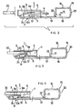
- FIGURE 1 is a perspective view of the electrical terminal according to the present invention with a matable contact exploded therefrom.
- FIGURE 2 is a side elevational view of the electrical terminal and matable contact of Figure 1.
- FIGURE 3 is a part cross-sectional view of the receptacle contact section in the initial insertion position of the matabie contact therein.
- FIGURE 4 is a part cross-sectional view of the receptacle contact section in the complete insertion position of the matable contact therein.
- FIGURE 5 is a top plan view of the metal blank from which the electrical terminal of Figure 1 is formed.
- The electrical terminal 1 according to the present invention is made from a metal sheet having desirable conductive and spring characteristics by stamping and folding a stamped blank along lines 31-38 shown in Figure 5.
- Electrical terminal 1 has a
receptacle contact section 3, the transverse cross-section of which is of a rectangular shape, and which has a contact-receiving area 4 for receiving therein amatable contact 30 having a tab configuration.Receptacle contact section 3 includes aresilient contact member 9 which is bent at a front end of thecontact section 3 along folding line 35 (Figure 5) and which is integral with abottom wall 5.Resilient contact member 9 extends backward within contact-receiving area 4 in a direction away frombottom wall 5 as a cantilever contact member and provides acontact surface 9b for electrical engagement withmatable contact 30, at the forward portion in a longitudinal direction thereof. An arcuatefree end 9a ofcontact member 9 is positioned at the longitudinal central portion of contact-receiving area 4 with a gap h between anupper wall 6 andfree end 9a. Gap h is less than a thickness t ofmatable contact 30 to be inserted betweenwall 6 andcontact member 9. - Spring-
assist member 10 is formed out ofbottom wall 5 by stamping therefrom and extends forward within contact-receiving area 4 from a rear portion ofbottom wall 5 and in a direction away frombottom wall 5. Afree end 10a of spring-assist member 10 is arcuate-shaped and is positioned adjacent arcuatefree end 9a ofcontact member 9. Bothmembers free ends -
Bottom wall 5 has aprojection 11 for engagement with a shoulder formed in a terminal-receiving cavity of an insulating housing (not shown) so that terminal 1 is retained in the housing. -
Contact section 3 has at the inner surface ofupper wall 6 two inwardly-projectingbeads 12 which extend in the longitudinal direction ofupper wall 6. Inwardly-projectingbeads 12 provide a contact surface formatable contact 30 to move along and they serve to reduce the frictional resistance ofcontact 30 when it is inserted in contact-receiving area 4. - Terminal 1 has an
extension 13 which extends backward as part ofbottom wall 5 and provides awire connecting section 14 which is formed by bending along folding lines 36-38 (Figure 5). Thewire connecting section 14 includes a pair ofparallel plates plates receiving slots plates bights plate 21 integral with and as an extension ofplate 15 extends towardplate 16. A free end of theplate 21abuts plate 16 and engages alance 22 extending outwardly fromextension 13. Lance 22 serves to preventplate 21 from being deformed in the direction of arrow A in Figure 2 when terminal 1 is inserted into the terminal-receiving cavity of the housing by pressing againstplate 21 with an insertion member (not shown) which is inserted betweenbights receiving slots - When
matable contact 30 is inserted into contact-receiving area 4 ofcontact section 3,matable contact 30 engagesresilient contact member 9, as shown in Figure 3, and presses thecontact member 9 towardbottom wall 5. In this initial inserting position of thecontact 30, thecontact 30 receives only the spring force ofresilient contact member 9 so that the insertion force is small. Contact 30 is then further inserted as shown in Figure 4, andresilient contact member 9 is further depressed so that its arcuatefree end 9a engagesfree end 10a of spring-assist member 10 and pressesmember 10 towardbottom wall 5. In this complete insertion position of thecontact 30 betweenbeads 12 andmember 9,contact 30 receives the combined spring force ofresilient contact member 9 and spring-assist member 10 so that a high contact pressure can be obtained. - According to the present invention, as is described above, the construction is such that the spring force of the resilient contact member only is applied to the matable contact in the initial insertion position of the matable contact in the contact-receiving area of a receptacle contact section of an electrical terminal, and the combined spring force of the resilient contact member and the spring-assist member is applied thereto at the complete insertion position of the matable contact within the contact-receiving area. Consequently, a low initial insertion force of the matable contact into the receptacle contact section can be obtained, and also, a high contact pressure can be obtained at the complete insertion position. In addition, both of the spring contact members constitute an independent cantilever, respectively, and the overlapping free ends with a gap therebetween can be displaced gently over a wide range. Therefore, if the matable contact is inserted into the receptacle contact section at an inappropriate insertion angle and, as a result, the resilient members are exceedingly displaced, the members are not permanently deformed. This makes possible electrical connections between a matable contact a receptacle contact section having various thicknesses. Furthermore, the ease of displacement of both free ends of the resilient members ensures smooth insertion of the matable contact after the initial insertion and the insertion force increases gradually in proportion to the depth of the insertion, and thus the operation efficiency increases.
- Due to initial low insertion forces required to mate the matable contacts in the receptacle contact sections and the insertion forces increasing gradually until complete insertion takes place, the present invention lends itself to connectors including many receptacle contact sections according to the present invention.
Claims (6)
Applications Claiming Priority (2)
| Application Number | Priority Date | Filing Date | Title |
|---|---|---|---|
| JP1983199108U JPS60110930U (en) | 1983-12-27 | 1983-12-27 | female electrical contact |
| JP199108/83 | 1983-12-27 |
Publications (3)
| Publication Number | Publication Date |
|---|---|
| EP0147076A2 true EP0147076A2 (en) | 1985-07-03 |
| EP0147076A3 EP0147076A3 (en) | 1986-12-30 |
| EP0147076B1 EP0147076B1 (en) | 1991-02-27 |
Family
ID=16402254
Family Applications (1)
| Application Number | Title | Priority Date | Filing Date |
|---|---|---|---|
| EP84308254A Expired - Lifetime EP0147076B1 (en) | 1983-12-27 | 1984-11-28 | Electrical terminal having a receptacle contact section of low insertion force and terminating section therefor |
Country Status (7)
| Country | Link |
|---|---|
| US (1) | US4838816A (en) |
| EP (1) | EP0147076B1 (en) |
| JP (1) | JPS60110930U (en) |
| BR (1) | BR8406615A (en) |
| DE (1) | DE3484188D1 (en) |
| ES (2) | ES292709Y (en) |
| MX (1) | MX156603A (en) |
Cited By (6)
| Publication number | Priority date | Publication date | Assignee | Title |
|---|---|---|---|---|
| EP0650223A1 (en) * | 1993-10-26 | 1995-04-26 | CONNECTEURS CINCH, Société Anonyme dite : | Female electrical contact terminal |
| WO1995028020A1 (en) * | 1994-04-12 | 1995-10-19 | Framatome Connectors International S.A. | Double-flexible-blade electric terminal |
| EP0687033A3 (en) * | 1994-06-06 | 1996-01-10 | Whitaker Corp | |
| FR2725839A1 (en) * | 1994-10-13 | 1996-04-19 | Framatome Connectors Int | Low voltage electrical contact for use in motor vehicle wiring connection |
| WO1996012324A1 (en) * | 1994-10-13 | 1996-04-25 | Framatome Connectors International | Electrical contact terminal comprising prestressed terminal blades |
| DE10103124B4 (en) * | 2000-01-24 | 2005-07-14 | Yazaki Corp. | female contact |
Families Citing this family (35)
| Publication number | Priority date | Publication date | Assignee | Title |
|---|---|---|---|---|
| GB2201049A (en) * | 1987-01-29 | 1988-08-17 | Brian Anthony Marshall | Electrical connector |
| JPH0735316Y2 (en) * | 1990-05-18 | 1995-08-09 | 日本エー・エム・ピー株式会社 | Receptacle type contact |
| FR2681985B1 (en) * | 1991-09-26 | 1993-12-31 | Souriau Cie | ELECTRICAL CONNECTOR. |
| JP2686199B2 (en) * | 1992-01-28 | 1997-12-08 | 矢崎総業株式会社 | Female terminal fitting |
| JPH0730466U (en) * | 1993-11-08 | 1995-06-06 | 住友電装株式会社 | Female terminal fittings for connectors |
| US5427552A (en) * | 1993-11-22 | 1995-06-27 | Chrysler Corporation | Electrical terminal and method of fabricating same |
| US5791945A (en) * | 1995-04-13 | 1998-08-11 | The Whitaker Corporation | High force contact |
| GB9519884D0 (en) * | 1995-09-29 | 1995-11-29 | Amp Great Britain | Electrical receptacle terminals |
| JPH09106854A (en) * | 1995-10-13 | 1997-04-22 | Yazaki Corp | Female terminal for water-proof connector and resin charged water-proof connector |
| US5897405A (en) * | 1997-05-29 | 1999-04-27 | Endo; Hiroshi | Electrical socket contact |
| JPH11283699A (en) * | 1998-03-31 | 1999-10-15 | Yazaki Corp | Connector structure |
| FR2809872B1 (en) * | 2000-05-30 | 2002-08-09 | Sylea | ELECTRICAL CONNECTION DEVICE FOR MALE ELECTRIC CONTACT MEMBER AND HOUSING ELEMENT FOR RECEIVING SUCH A DEVICE |
| US6428366B1 (en) | 2000-11-03 | 2002-08-06 | Molex Incorporated | Electrical terminal socket and method of fabricating same |
| JP4379231B2 (en) * | 2004-07-07 | 2009-12-09 | 住友電装株式会社 | Female terminal bracket |
| DE102004037134A1 (en) * | 2004-07-30 | 2006-03-23 | Robert Bosch Gmbh | Socket part for producing an electrical plug connection with an additional spring element |
| US7249983B2 (en) * | 2005-05-19 | 2007-07-31 | Deutsch Engineered Connecting Devices | Sleeveless stamped and formed socket contact |
| JP4552781B2 (en) * | 2005-07-05 | 2010-09-29 | 住友電装株式会社 | Terminal fitting |
| US7387550B2 (en) * | 2005-07-21 | 2008-06-17 | Tyco Electronics Corporation | Dual beam receptacle contact |
| US7264518B2 (en) * | 2005-12-12 | 2007-09-04 | Tyco Electronics Corporation | Electrical contact including integral stop member |
| JP2007250362A (en) * | 2006-03-16 | 2007-09-27 | Toyota Motor Corp | Connector structure and connector type terminal board structure |
| US7618279B1 (en) * | 2008-06-26 | 2009-11-17 | Thomas & Betts International, Inc. | One-piece push-in electrical contact terminal |
| JP2011181330A (en) * | 2010-03-01 | 2011-09-15 | Sumitomo Wiring Syst Ltd | Terminal fitting |
| US8333622B2 (en) * | 2010-12-06 | 2012-12-18 | Delphi Technologies, Inc. | Dual contact beam terminal |
| JP5803798B2 (en) * | 2012-04-26 | 2015-11-04 | 住友電装株式会社 | Terminal fitting |
| JP2014160545A (en) * | 2013-02-19 | 2014-09-04 | Sumitomo Wiring Syst Ltd | Female terminal metal fitting |
| JP2014170709A (en) * | 2013-03-05 | 2014-09-18 | Sumitomo Wiring Syst Ltd | Female terminal fitting |
| JP6107407B2 (en) * | 2013-05-20 | 2017-04-05 | Smk株式会社 | Card connector |
| JP5999510B2 (en) * | 2013-05-30 | 2016-09-28 | 住友電装株式会社 | Female terminal fitting and manufacturing method thereof |
| JP2015103410A (en) * | 2013-11-26 | 2015-06-04 | 矢崎総業株式会社 | Connection terminal |
| EP3414797A4 (en) | 2016-02-08 | 2019-10-23 | Molex, LLC | Terminal fitting |
| DE102016123162B4 (en) * | 2016-11-30 | 2022-05-19 | Lear Corporation | TWO PIECE ELECTRICAL PLUG AND METHOD OF CONNECTING THE SAME |
| JP6780571B2 (en) * | 2017-04-10 | 2020-11-04 | 住友電装株式会社 | Terminal bracket |
| CN110854559A (en) | 2018-08-20 | 2020-02-28 | 松下·万宝(广州)压缩机有限公司 | Terminal sealing cover, upper cover assembly and compressor |
| JP7194332B2 (en) * | 2019-03-12 | 2022-12-22 | 株式会社オートネットワーク技術研究所 | Terminals, connectors and connector constructs |
| JP7314012B2 (en) * | 2019-10-07 | 2023-07-25 | 日本航空電子工業株式会社 | Socket contacts and connectors |
Citations (7)
| Publication number | Priority date | Publication date | Assignee | Title |
|---|---|---|---|---|
| DE1011957B (en) * | 1955-09-29 | 1957-07-11 | Arnstadt Fernmeldewerk | Plug receiving contact |
| US3152857A (en) * | 1962-03-05 | 1964-10-13 | B & C Metal Stamping Company | Terminal for electrical meter socket |
| US3977757A (en) * | 1975-03-17 | 1976-08-31 | General Motors Corporation | Wipe-in female terminal for printed circuits |
| GB1497274A (en) * | 1975-04-22 | 1978-01-05 | Pressac Ltd | Electric connectors or couplings |
| FR2412962A1 (en) * | 1977-12-22 | 1979-07-20 | Socapex | CONTACT ELEMENT FOR SELF-STRIPPING CONNECTOR, AND CONNECTOR EQUIPPED WITH SUCH A CONTACT ELEMENT |
| US4227763A (en) * | 1979-04-09 | 1980-10-14 | Amp Incorporated | Commoning connector |
| EP0171193A2 (en) * | 1984-08-03 | 1986-02-12 | General Motors Corporation | Duplex sheet metal insulation displacement terminal |
Family Cites Families (6)
| Publication number | Priority date | Publication date | Assignee | Title |
|---|---|---|---|---|
| US31142A (en) * | 1861-01-15 | Machine for dressing millstones | ||
| JPS5230361Y2 (en) * | 1975-08-12 | 1977-07-11 | ||
| US4068915A (en) * | 1975-09-22 | 1978-01-17 | E. I. Du Pont De Nemours And Company | Electrical connector |
| US4139256A (en) * | 1977-09-15 | 1979-02-13 | North American Specialties Corp. | Electrical contact and method of making same |
| JPS54102590A (en) * | 1978-01-31 | 1979-08-13 | Yazaki Corp | Electric connector |
| US4357066A (en) * | 1980-05-27 | 1982-11-02 | Ford Motor Company | Printed circuit board edge terminal |
-
1983
- 1983-12-27 JP JP1983199108U patent/JPS60110930U/en active Pending
-
1984
- 1984-10-26 US US06/665,339 patent/US4838816A/en not_active Expired - Fee Related
- 1984-11-28 DE DE8484308254T patent/DE3484188D1/en not_active Expired - Fee Related
- 1984-11-28 EP EP84308254A patent/EP0147076B1/en not_active Expired - Lifetime
- 1984-12-20 BR BR8406615A patent/BR8406615A/en not_active IP Right Cessation
- 1984-12-20 MX MX84203855A patent/MX156603A/en unknown
- 1984-12-26 ES ES1984292709U patent/ES292709Y/en not_active Expired
-
1985
- 1985-12-26 ES ES1985291292U patent/ES291292Y/en not_active Expired
Patent Citations (7)
| Publication number | Priority date | Publication date | Assignee | Title |
|---|---|---|---|---|
| DE1011957B (en) * | 1955-09-29 | 1957-07-11 | Arnstadt Fernmeldewerk | Plug receiving contact |
| US3152857A (en) * | 1962-03-05 | 1964-10-13 | B & C Metal Stamping Company | Terminal for electrical meter socket |
| US3977757A (en) * | 1975-03-17 | 1976-08-31 | General Motors Corporation | Wipe-in female terminal for printed circuits |
| GB1497274A (en) * | 1975-04-22 | 1978-01-05 | Pressac Ltd | Electric connectors or couplings |
| FR2412962A1 (en) * | 1977-12-22 | 1979-07-20 | Socapex | CONTACT ELEMENT FOR SELF-STRIPPING CONNECTOR, AND CONNECTOR EQUIPPED WITH SUCH A CONTACT ELEMENT |
| US4227763A (en) * | 1979-04-09 | 1980-10-14 | Amp Incorporated | Commoning connector |
| EP0171193A2 (en) * | 1984-08-03 | 1986-02-12 | General Motors Corporation | Duplex sheet metal insulation displacement terminal |
Cited By (7)
| Publication number | Priority date | Publication date | Assignee | Title |
|---|---|---|---|---|
| EP0650223A1 (en) * | 1993-10-26 | 1995-04-26 | CONNECTEURS CINCH, Société Anonyme dite : | Female electrical contact terminal |
| FR2711853A1 (en) * | 1993-10-26 | 1995-05-05 | Cinch Connecteurs Sa | Female electrical contact member. |
| WO1995028020A1 (en) * | 1994-04-12 | 1995-10-19 | Framatome Connectors International S.A. | Double-flexible-blade electric terminal |
| EP0687033A3 (en) * | 1994-06-06 | 1996-01-10 | Whitaker Corp | |
| FR2725839A1 (en) * | 1994-10-13 | 1996-04-19 | Framatome Connectors Int | Low voltage electrical contact for use in motor vehicle wiring connection |
| WO1996012324A1 (en) * | 1994-10-13 | 1996-04-25 | Framatome Connectors International | Electrical contact terminal comprising prestressed terminal blades |
| DE10103124B4 (en) * | 2000-01-24 | 2005-07-14 | Yazaki Corp. | female contact |
Also Published As
| Publication number | Publication date |
|---|---|
| DE3484188D1 (en) | 1991-04-04 |
| EP0147076A3 (en) | 1986-12-30 |
| JPS60110930U (en) | 1985-07-27 |
| ES292709Y (en) | 1987-03-01 |
| MX156603A (en) | 1988-09-14 |
| ES291292U (en) | 1986-04-16 |
| BR8406615A (en) | 1985-10-15 |
| ES291292Y (en) | 1986-12-16 |
| EP0147076B1 (en) | 1991-02-27 |
| US4838816A (en) | 1989-06-13 |
| ES292709U (en) | 1986-06-16 |
Similar Documents
| Publication | Publication Date | Title |
|---|---|---|
| US4838816A (en) | Electrical terminal having a receptacle contact section of low insertion force | |
| US4699444A (en) | Electrical receptacle which assures positive connection | |
| US5007865A (en) | Electrical receptacle terminal | |
| US3208030A (en) | Electrical connector | |
| US4416504A (en) | Contact with dual cantilevered arms with narrowed, complimentary tip portions | |
| JP4187338B2 (en) | Electrical connector | |
| US5697815A (en) | Electrical connectors | |
| US6386918B1 (en) | Retention element for electrical connector | |
| US6010377A (en) | High contact force pin-receiving electrical terminal | |
| US5133672A (en) | Insulation displacement terminal | |
| JP2631258B2 (en) | Male electrical terminal having excessive stress prevention means | |
| US6918799B2 (en) | Electrical connector having contact with pre-pressing structure | |
| US6231393B1 (en) | Electrical connector | |
| US6629864B2 (en) | Electrical contact for plug-in connector | |
| US4583813A (en) | Low profile electrical connector assembly | |
| JPH0220763Y2 (en) | ||
| EP0117021B1 (en) | Socket connector | |
| US6971923B1 (en) | Cable end connector assembly with improved organizer | |
| US4909762A (en) | Electric connector | |
| US6186833B1 (en) | Hybrid connector with audio jack | |
| JP3523030B2 (en) | Terminal structure | |
| JP2850109B2 (en) | Connection terminal | |
| JPH069149B2 (en) | Connecting terminal | |
| CN113517584A (en) | Connection terminal and connector | |
| US6454617B1 (en) | Electrical connector with improved terminals |
Legal Events
| Date | Code | Title | Description |
|---|---|---|---|
| PUAI | Public reference made under article 153(3) epc to a published international application that has entered the european phase |
Free format text: ORIGINAL CODE: 0009012 |
|
| AK | Designated contracting states |
Designated state(s): BE DE FR GB IT NL SE |
|
| PUAL | Search report despatched |
Free format text: ORIGINAL CODE: 0009013 |
|
| AK | Designated contracting states |
Kind code of ref document: A3 Designated state(s): BE DE FR GB IT NL SE |
|
| 17P | Request for examination filed |
Effective date: 19870613 |
|
| 17Q | First examination report despatched |
Effective date: 19881027 |
|
| RAP3 | Party data changed (applicant data changed or rights of an application transferred) |
Owner name: AMP INCORPORATED (A NEW JERSEY CORPORATION) |
|
| RAP1 | Party data changed (applicant data changed or rights of an application transferred) |
Owner name: AMP INCORPORATED |
|
| GRAA | (expected) grant |
Free format text: ORIGINAL CODE: 0009210 |
|
| AK | Designated contracting states |
Kind code of ref document: B1 Designated state(s): BE DE FR GB IT NL SE |
|
| ITF | It: translation for a ep patent filed | ||
| REF | Corresponds to: |
Ref document number: 3484188 Country of ref document: DE Date of ref document: 19910404 |
|
| ET | Fr: translation filed | ||
| PLBE | No opposition filed within time limit |
Free format text: ORIGINAL CODE: 0009261 |
|
| STAA | Information on the status of an ep patent application or granted ep patent |
Free format text: STATUS: NO OPPOSITION FILED WITHIN TIME LIMIT |
|
| 26N | No opposition filed | ||
| REG | Reference to a national code |
Ref country code: GB Ref legal event code: 732E |
|
| EAL | Se: european patent in force in sweden |
Ref document number: 84308254.6 |
|
| PGFP | Annual fee paid to national office [announced via postgrant information from national office to epo] |
Ref country code: BE Payment date: 19971211 Year of fee payment: 14 |
|
| PGFP | Annual fee paid to national office [announced via postgrant information from national office to epo] |
Ref country code: NL Payment date: 19980914 Year of fee payment: 15 |
|
| PGFP | Annual fee paid to national office [announced via postgrant information from national office to epo] |
Ref country code: GB Payment date: 19981008 Year of fee payment: 15 |
|
| PGFP | Annual fee paid to national office [announced via postgrant information from national office to epo] |
Ref country code: SE Payment date: 19981105 Year of fee payment: 15 |
|
| PGFP | Annual fee paid to national office [announced via postgrant information from national office to epo] |
Ref country code: FR Payment date: 19981109 Year of fee payment: 15 |
|
| PGFP | Annual fee paid to national office [announced via postgrant information from national office to epo] |
Ref country code: DE Payment date: 19981125 Year of fee payment: 15 |
|
| PG25 | Lapsed in a contracting state [announced via postgrant information from national office to epo] |
Ref country code: BE Free format text: LAPSE BECAUSE OF NON-PAYMENT OF DUE FEES Effective date: 19981130 |
|
| BERE | Be: lapsed |
Owner name: AMP INC. Effective date: 19981130 |
|
| PG25 | Lapsed in a contracting state [announced via postgrant information from national office to epo] |
Ref country code: GB Free format text: LAPSE BECAUSE OF NON-PAYMENT OF DUE FEES Effective date: 19991128 |
|
| PG25 | Lapsed in a contracting state [announced via postgrant information from national office to epo] |
Ref country code: SE Free format text: LAPSE BECAUSE OF NON-PAYMENT OF DUE FEES Effective date: 19991129 |
|
| PG25 | Lapsed in a contracting state [announced via postgrant information from national office to epo] |
Ref country code: NL Free format text: LAPSE BECAUSE OF NON-PAYMENT OF DUE FEES Effective date: 20000601 |
|
| EUG | Se: european patent has lapsed |
Ref document number: 84308254.6 |
|
| GBPC | Gb: european patent ceased through non-payment of renewal fee |
Effective date: 19991128 |
|
| PG25 | Lapsed in a contracting state [announced via postgrant information from national office to epo] |
Ref country code: FR Free format text: LAPSE BECAUSE OF NON-PAYMENT OF DUE FEES Effective date: 20000731 |
|
| NLV4 | Nl: lapsed or anulled due to non-payment of the annual fee |
Effective date: 20000601 |
|
| PG25 | Lapsed in a contracting state [announced via postgrant information from national office to epo] |
Ref country code: DE Free format text: LAPSE BECAUSE OF NON-PAYMENT OF DUE FEES Effective date: 20000901 |
|
| REG | Reference to a national code |
Ref country code: FR Ref legal event code: ST |