EP0147013B1 - Perforating screen and method of making it - Google Patents
Perforating screen and method of making it Download PDFInfo
- Publication number
- EP0147013B1 EP0147013B1 EP84306398A EP84306398A EP0147013B1 EP 0147013 B1 EP0147013 B1 EP 0147013B1 EP 84306398 A EP84306398 A EP 84306398A EP 84306398 A EP84306398 A EP 84306398A EP 0147013 B1 EP0147013 B1 EP 0147013B1
- Authority
- EP
- European Patent Office
- Prior art keywords
- screen
- screens
- thin
- holes
- metal
- Prior art date
- Legal status (The legal status is an assumption and is not a legal conclusion. Google has not performed a legal analysis and makes no representation as to the accuracy of the status listed.)
- Expired - Lifetime
Links
Images


Classifications
-
- B—PERFORMING OPERATIONS; TRANSPORTING
- B23—MACHINE TOOLS; METAL-WORKING NOT OTHERWISE PROVIDED FOR
- B23P—METAL-WORKING NOT OTHERWISE PROVIDED FOR; COMBINED OPERATIONS; UNIVERSAL MACHINE TOOLS
- B23P15/00—Making specific metal objects by operations not covered by a single other subclass or a group in this subclass
- B23P15/26—Making specific metal objects by operations not covered by a single other subclass or a group in this subclass heat exchangers or the like
-
- B—PERFORMING OPERATIONS; TRANSPORTING
- B23—MACHINE TOOLS; METAL-WORKING NOT OTHERWISE PROVIDED FOR
- B23P—METAL-WORKING NOT OTHERWISE PROVIDED FOR; COMBINED OPERATIONS; UNIVERSAL MACHINE TOOLS
- B23P15/00—Making specific metal objects by operations not covered by a single other subclass or a group in this subclass
- B23P15/16—Making specific metal objects by operations not covered by a single other subclass or a group in this subclass plates with holes of very small diameter, e.g. for spinning or burner nozzles
-
- B—PERFORMING OPERATIONS; TRANSPORTING
- B26—HAND CUTTING TOOLS; CUTTING; SEVERING
- B26F—PERFORATING; PUNCHING; CUTTING-OUT; STAMPING-OUT; SEVERING BY MEANS OTHER THAN CUTTING
- B26F1/00—Perforating; Punching; Cutting-out; Stamping-out; Apparatus therefor
- B26F1/26—Perforating by non-mechanical means, e.g. by fluid jet
-
- Y—GENERAL TAGGING OF NEW TECHNOLOGICAL DEVELOPMENTS; GENERAL TAGGING OF CROSS-SECTIONAL TECHNOLOGIES SPANNING OVER SEVERAL SECTIONS OF THE IPC; TECHNICAL SUBJECTS COVERED BY FORMER USPC CROSS-REFERENCE ART COLLECTIONS [XRACs] AND DIGESTS
- Y10—TECHNICAL SUBJECTS COVERED BY FORMER USPC
- Y10T—TECHNICAL SUBJECTS COVERED BY FORMER US CLASSIFICATION
- Y10T29/00—Metal working
- Y10T29/49—Method of mechanical manufacture
- Y10T29/49826—Assembling or joining
- Y10T29/49908—Joining by deforming
- Y10T29/49938—Radially expanding part in cavity, aperture, or hollow body
- Y10T29/4994—Radially expanding internal tube
-
- Y—GENERAL TAGGING OF NEW TECHNOLOGICAL DEVELOPMENTS; GENERAL TAGGING OF CROSS-SECTIONAL TECHNOLOGIES SPANNING OVER SEVERAL SECTIONS OF THE IPC; TECHNICAL SUBJECTS COVERED BY FORMER USPC CROSS-REFERENCE ART COLLECTIONS [XRACs] AND DIGESTS
- Y10—TECHNICAL SUBJECTS COVERED BY FORMER USPC
- Y10T—TECHNICAL SUBJECTS COVERED BY FORMER US CLASSIFICATION
- Y10T428/00—Stock material or miscellaneous articles
- Y10T428/12—All metal or with adjacent metals
- Y10T428/12361—All metal or with adjacent metals having aperture or cut
-
- Y—GENERAL TAGGING OF NEW TECHNOLOGICAL DEVELOPMENTS; GENERAL TAGGING OF CROSS-SECTIONAL TECHNOLOGIES SPANNING OVER SEVERAL SECTIONS OF THE IPC; TECHNICAL SUBJECTS COVERED BY FORMER USPC CROSS-REFERENCE ART COLLECTIONS [XRACs] AND DIGESTS
- Y10—TECHNICAL SUBJECTS COVERED BY FORMER USPC
- Y10T—TECHNICAL SUBJECTS COVERED BY FORMER US CLASSIFICATION
- Y10T428/00—Stock material or miscellaneous articles
- Y10T428/12—All metal or with adjacent metals
- Y10T428/12479—Porous [e.g., foamed, spongy, cracked, etc.]
Definitions
- the present invention is in the general field of perforated plastic film and especially relates to vacuum perforating of plastic film.
- the invention particularly relates to metal screens or molding elements used in the vacuum perforation of plastic film and to a method of fabricating such screens.
- Perforated plastic film has many useful applications. It is used in gardening and farming to prevent the growth of grass and weeds while permitting moisture to be transmitted through the film to the soil beneath. Perforated film is also used for making disposable diapers, for example, see U.S. 3,814,101.
- U.S. 3,054,148 One of the earlier methods for vacuum perforation of plastic film is disclosed in U.S. 3,054,148.
- the patentee describes a stationary drum having a molding element or screen mounted around the outer surface of the drum and adapted to freely rotate thereon.
- a vacuum chamber is employed beneath the screen to create a pressure differential between the respective surfaces of the thermoplastic sheet to be perforated to cause the plasticized sheet to flow into openings provided in the screen and thereby cause a series of openings, holes or perforations to be formed in the plastic sheet or film.
- U.S. 4,155,693 U.S. 4,252,516, U.S. 3,709,647, U.S. 4,151,240, U.S. 4,319,868 and U.S. 4,388,056.
- the screen is comprised of a series of perforated metal strips preferably welded together to form a cylinder.
- U.S. 4,252,516 provides a screen having a series of hexagonal depressions with elliptical holes centered therein.
- U.S. 3,709,647 provides for a rotating vacuum-forming roll having a circulating cooling medium therein.
- U.S. 4,342,314 discloses a method for forming a planar forming surface or a cylindrical forming surface, each of such surfaces being used to emboss or perforate film.
- the method, and thus the resultant forming surface is obtained by first bonding together a plurality of laminae so that the pattern cut in each of the lamina is in alignment with the pattern in all other of the laminae.
- the various laminae, after bonding, are joined together at two of their opposite ends by means of a seam.
- U.S. 4,151,240 provides a means for cooling the film after it has been perforated and debossed.
- U.S. 4,319,868 sets forth an apparatus for making a thermoplastic film having raised bosses with perforated tips. A particularly constructed embossing roll for effecting the desired film pattern is disclosed.
- U.S. 4,388,056 discloses an apparatus for continuously forming an airlaid fibrous web having oppositely phased, cylindrically undulating side edges and a predetermined basis weight distribution.
- An air-laying drum has a honeycomb type annular-shape frame including circumferentially extending ribs and transverse plates.
- a stationary adjustable air flow modulating means is disposed adjacent the radially inwardly disposed boundary of an arcuate portion of a circumferentially segmented annular-shape plenum, circumferentially spanning a plurality of plenum segments for adjusting a pressure drop across particular areas of the surface of the air-laying drum.
- Vacuum perforation of thin plastic films involves the extrusion of molten polymeric materials such as polyethylene and other plastic polymers though a slot die.
- the hot melt web of film or plastic sheet exiting the die impinges on a rotating cylindrical screen which is mounted on a stationary vacuum drum or roll.
- the vacuum roll has an axial slot and a set of seals extending longitudinally the length of its outside surface, beneath the area where the web of plastic impinges on the screen or molding element.
- a high vacuum from inside the screen is directed through the slot in the vacuum roll.
- the vacuum present within the slot forms or molds the plastic film or sheet to the screen and perforates it through the holes of the screen. At the same time, an airflow is produced which cools the film.
- the most important component of the vacuum processing equipment is the cylindrical screen.
- This molding element defines aesthetic and mechanical properties of the film as well as the geometric pattern of the perforated film.
- the desired screen pattern is nickel plated on a specially prepared cylindrical mandrel.
- a seamless cylindrical nickel screen of any predetermined or desired pattern can be produced.
- Other metals, such as copper may also be used.
- Some film products require the use of relatively thick screens, e.g. from 0.020 to 0.100 inches (0.0508 - 0.254 cm) thick, and also require that the walls of the patterned holes are straight and perpendicular to the screen surface.
- Present screen fabrication techniques as heretofore described are not capable of producing a screen meeting these requirements.
- the patterned holes on screens produced by nickel plating a prepared cylindrical mandrel, even with the application of specialized plating and post etching techniques, take the shape of inverted, truncated, concaved cones. The thicker the screen, the more exaggerated the effect becomes.
- This invention provides a laminated, seamless, cylindrical metal screen or molding element for vacuum perforation of plastic film or sheets, comprising two or more thin, seamless, cylindrical metal screens, each of the thin screens having a plurality of openings or holes therein, the thin screens being stacked and bonded together diametrically one inside the other to provide the laminated cylindrical metal screen, the holes of each of the thin screens being substantially aligned with the holes of the other screen or screens and each of the holes in the thin screens having a radial centreline aligned with the radial centreline of the or each aligned hole of the other thin screen or screens.
- the invention includes a method of making a thick cylindrical metal screen or molding element for vacuum perforation of plastic film or sheets, comprising stacking and bonding together two or more matched thin, seamless, cylindrical metal screens, each of the thin screens having a plurality of openings or holes therein and the thin screens being stacked and bonded together diametrically one inside the other to provide the thick cylindrical metal screen, the holes of each of the thin screens being substantially aligned with the holes of the other screen or screens and each of the holes in the thin screens having a radial centreline aligned with the radial centreline of the or each aligned hole of the other thin screen or screens.
- the invention provides a method of fabricating a laminated, cylindrical metal screen or molding element for vacuum perforation of plastic film or sheets, comprising the steps of:
- Any remaining flux may be removed with an appropriate agent and the inside sleeve is removed thereby leaving a finished laminated screen product of desired specifications.
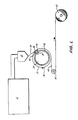
- Figure 1 is a schematic view illustration of an apparatus and method for vacuum perforation of thermoplastic film
- Figure 2 is a side elevational view of a sleeve mounted in a cradle with a screen partially inserted therein;
- Figure 3 is an end view of the assembly of Figure 2 with the wall thickness of the screen and sleeve enlarged to show detail;
- Figure 4 is an end view similar to that of Figure 3, but illustrates a complete assembly of screens and sleeves
- Figure 5 is a perspective view of a laminated screen of the invention.
- Figure 6 is an enlarged view of a segment of the screen of Figure 5;
- Figure 7 is a sectional view of the screen segment of Figure 6 taken along line 7-7;
- Figure 8 is a sectional view of a screen segment similar to that of Figure 7 illustrating an alternate hole radial cross-section;
- Figure 9 is a sectional view of a screen segment similar to that of Figure 7 illustrating another alternate hole radial cross-section.
- Figure 10 is a sectional view of a screen segment similar to that of Figure 7 illustrating still another alternate hole radial cross-section.
- FIG. 1 of the drawings vacuum process equipment and method for perforating plastic film or sheet therewith are schematically illustrated.
- a plastic polymer such as polyethylene is heated to a melt and extruded from an extruder E through a die D where a film web 10 is formed.
- the web 10 is directed onto a rotating cylindrical screen 11 having a desired pattern of holes which is turning clockwise as indicated by arrow A around a stationary vacuum roll or drum 12.
- a vacuum chamber 13 within the roll 12, longitudinal air slot 14 and seals 15 are employed to create a pressure differential between the respective surfaces of the thermoplastic sheet or web 10 to cause the plasticized sheet to flow into the holes in the screen in the direction indicated by the arrow B and therefore perforate the web 30.
- the perforated film web 10' travels onto a guide roll 16 and continues onto a wind-up roll It. Additional guide rolls or tensioning rolls can be employed as desired as well as various film treating equipment.
- Seamless cylindrical nickel screens produced by plating are made by two principal methods.
- a mandrel is ground to a dimension corresponding to the desired dimension of the finished screen.
- the desired screen hole pattern is engraved on the mandrel either by spiral engraving or malett indexing techniques.
- a plating resist medium is applied to the surface of the mandrel, filling the pattern produced by the engraving.
- a finish grinding operation is employed to remove the plating resist medium from the land areas between the engraved pattern, so that only the land area will be subject to plating.
- Subsequent nickel plating of the mandrel forms the screen.
- the mandrel is cooled and the finished screen is removed therefrom.
- the other method of producing a seamless cylindrical nickel screen is similar to the foregoing method, except that instead of engraving the pattern on the mandrel, a special photographic negative of the pattern is created and wrapped around the mandrel. Exposing of the negative transfers the pattern to the mandrel in the form of a plating resist, leaving only the land areas of the screen available for plating. The mandrel is then plated, forming the screen which is then removed from the mandrel to obtain the finished product.
- each successive screen of the set must fit diametrically inside the next larger diameter screen, with sufficient space allowed for the metal or tin-lead alloy plating of each screen.
- each screen of the set is typically geometrically identical. This means that each screen has the same number of holes, both axially and circumferentially, and that the radial centerlines of each hole of any one screen match identically the radial centerlines of the corresponding holes in all other screens in the set.
- the individual hole geometry of all the aligned holes in all the screens must generally be nearly identical.
- matched sets of seamless, cylindrical metal (nickel) screens may be produced as follows:
- screens are generally prepared for particular film perforating operations, the use of the same mandrel is preferable. Should a number of laminated screens of the same pattern be produced, a number of mandrels may be used, as appropriate.
- a matched set of thin, seamless, cylindrical, nickel screens are prepared as set forth in detail hereinafter.
- the length and diameter of the screens is selected on the basis of the type of vacuum perforating equipment and the number of screens to be laminated.
- the thickness of each screen is determined on the basis of the type of hole wall shape desired.
- a screen thickness of approximately 0.005 inches (0.0127 cm) is preferred for providing hole walls that are substantially straight and perpendicular to the surface of the screen.
- Each screen of the matched set is overplated with a thin layer of a bonding material, preferably a tin-lead alloy.
- a bonding material preferably a tin-lead alloy.
- An alloy of 63 weight percent tin and 37 percent lead is especially preferred.
- An alloy layer of about 0.00025 inches (0.000635 centimeters) thick is most preferred.
- Each screen of the matched set is designed and produced so that after plating, the inside diameter of the largest screen fits, within a specified tolerance, the outside diameter of the next largest screen. In turn, each screen of the set fits similarly inside the next largest screen.
- Each screen of the set is designed and produced with a common reference or aligning mark at each end thereof. Alignment of the reference marks during assembly produces proper pattern hole alignment.
- Two seamless cylindrical nickel sleeves of different diameters are also required.
- the sleeves are about the same length of the thin screens.
- the thickness of the sleeves may be varied, but a thickness of approximately 0.010 inches (0.0254 centimeters) is especially preferred.
- the inside surface of the larger diameter sleeve, and the outside surface of the smaller diameter sleeve are chrome plated. A plating thickness of about 0.0005 inches 0.00127 centimeters) is most preferred.
- the sleeves are designed and produced so that after chrome plating, the inside diameter of the larger sleeve fits, within a specified tolerance, the outside diameter of the largest diameter thin screen, after the screen has been plated.
- the outside diameter of the smaller sleeve is designed and produced to fit the inside diameter of the smallest diameter thin screen of the matched set of screens, after the screen has been plated.
- the two sleeves are used as fixtures during the assembly and bonding operations as explained hereinafter.
- the tin-lead alloy plating applied to each screen provides the bonding medium for lamination.
- the chrome plating applied to the sleeves acts as a resist to prevent the tin screens being laminated from bonding to the sleeves.
- the larger cylindrical sleeve 20 is mounted in a cradle 21 and restrained therein so as to retain its cylindrical shape by two stiff outside diameter ring clamps 22 and 23. Any other suitable restraining or clamping means may be used.
- the largest diameter thin screen 30 of the matched set of screens is malformed or otherwise distorted and slid or positioned inside the larger diameter sleeve 20. The screen 30 is then reformed into its cylindrical shape.
- the next largest screen 3l is similarly malformed and slid inside the largest screen 30 of the assembly 40.
- Reference marks 32 on the ends of the two screens are aligned and the screens are pinned or otherwise fastened together.
- the remaining thin screens are similarly installed with the next largest thin screen being positioned inside the second thin screen 31 and so on, until each thin screen of the matched set of thin screens has been assembled.
- the smaller sleeve 24 is positioned within the smallest diameter thin screen in the same manner as the various thin screens were installed.
- an appropriate flux for example, a liquid solder flux having a pure resin base or a soldering paste containing zinc chloride, both manufactured by CG Electronics. Any other suitable flux may be used.
- the assembly 40 is transferred to an oven and uniformly heated to a temperature of about 400°F + 10°F (204.4°C + 5.56°C) or 390°F to 410°F (or 198.84°C to 209.96°C).
- the cylindrical nickel sleeves remain on the assembled screens.
- the sleeves act to uniformly restrain the screen laminates while permitting growth and shrinkage during heating and cooling cycles as they are preferably of the same material as the thin screens.
- the assembly is then allowed to cool in the oven to nearly room or ambient temperature. It is then removed from the oven for final operations.
- the outside sleeve is carefully axially cut and removed. Remaining flux residue is removed from the screen assembly with a suitable agent, for example, by washing with a degreasing liquid followed by a neutralizing wash of a 2 percent solution of muriatic acid. Any other suitable flux removing agent may be used.
- a suitable agent for example, by washing with a degreasing liquid followed by a neutralizing wash of a 2 percent solution of muriatic acid. Any other suitable flux removing agent may be used.
- the inside sleeve is then removed, leaving a finished laminated screen of a desired thickness.
- the specific one of 63% tin-37% lead, plated to a thickness of 0.00025 inches (0.000635 centimeters) particularly meets the requirements of the fabricating system.
- Pure, plated nickel initiates embrittlement at approximately 425°F (218.3°C). Any bonding system selected must therefore cure or flow at a temperature below the embrittlement temperature of the nickel plating.
- the tin-lead alloy preferred is the eutectic formulation of the two elements. The alloy melts and solidifies at 361°F (182.3°C).
- the instant bonding system is unique, in that, by plating each individual thin screen prior to assembly, difficult and messy applications of bonding mediums during assembly are avoided.
- the tin-lead alloy plating thickness of 0.00025 inches (0.000635 centimeters) is the optimum thickness to produce good bonding with minimum excess alloy.
- a laminated screen 50 of the invention which comprises four thin screens 51, 52, 53 and 54 which have been stacked and bonded together in accordance with the foregoing procedure.
- the screen 50 has a plurality of openings or holes 50a therein.
- the holes 50a have walls 50b which are substantially straight as best seen in Fig. 7.
- the walls 50b are formed from the individual walls 51b, 52b, 53b and 54b of each of the tin screens 51, 52, 53 and 54, respectively.
- the truncated holes of the thin screens have been exaggerated.
- the effect of the multiscreen lamination provides hole walls which are substantially straight.
- the invention is particularly directed to a method of producing relatively thick seamless cylindrical metal screens, especially nickel screens, with holes or openings which are essentially straight and perpendicular to the screen surface
- the method can also be utilized to provide thick screens with an expanded variety of hole radial cross-sections. It is only essential that the basic hole radial centerlines of each screen laminate be the same.
- Figs. 8-10 illustrate some of the screen arrangements that can be achieved by using thin screens of different hole sizes. It can readily be appreciated that a wide variety of hole shapes and sizes can be obtained for providing a particular hole effect in a thermoplastic film or sheet. It is preferred for the holes to have a diameter of from about 0.015 to about 0.02 inches (0.0381 - 0.0508 cm). It is also preferred for there to about 100 to 20,000 holes per square inch (15.5 to 3100 holes/cm2) of screen surface.
- thermoplastic sheets or film made from polyolefins especially polyethylene and polypropylene
- it can be used with other types of thermoplastic films as desired.
Description
- The present invention is in the general field of perforated plastic film and especially relates to vacuum perforating of plastic film. The invention particularly relates to metal screens or molding elements used in the vacuum perforation of plastic film and to a method of fabricating such screens.
- Perforated plastic film has many useful applications. It is used in gardening and farming to prevent the growth of grass and weeds while permitting moisture to be transmitted through the film to the soil beneath. Perforated film is also used for making disposable diapers, for example, see U.S. 3,814,101.
- One of the earlier methods for vacuum perforation of plastic film is disclosed in U.S. 3,054,148. The patentee describes a stationary drum having a molding element or screen mounted around the outer surface of the drum and adapted to freely rotate thereon. A vacuum chamber is employed beneath the screen to create a pressure differential between the respective surfaces of the thermoplastic sheet to be perforated to cause the plasticized sheet to flow into openings provided in the screen and thereby cause a series of openings, holes or perforations to be formed in the plastic sheet or film.
- A variety of methods and apparatuses including particular types of perforating screens or rotatable molding elements have been developed over the years for particular perforation operations. Examples of these are U.S. 4,155,693, U.S. 4,252,516, U.S. 3,709,647, U.S. 4,151,240, U.S. 4,319,868 and U.S. 4,388,056. In U.S. 4,155,693, the screen is comprised of a series of perforated metal strips preferably welded together to form a cylinder. U.S. 4,252,516 provides a screen having a series of hexagonal depressions with elliptical holes centered therein. U.S. 3,709,647 provides for a rotating vacuum-forming roll having a circulating cooling medium therein.
- U.S. 4,342,314 discloses a method for forming a planar forming surface or a cylindrical forming surface, each of such surfaces being used to emboss or perforate film. The method, and thus the resultant forming surface, is obtained by first bonding together a plurality of laminae so that the pattern cut in each of the lamina is in alignment with the pattern in all other of the laminae. The various laminae, after bonding, are joined together at two of their opposite ends by means of a seam.
- U.S. 4,151,240 provides a means for cooling the film after it has been perforated and debossed. U.S. 4,319,868 sets forth an apparatus for making a thermoplastic film having raised bosses with perforated tips. A particularly constructed embossing roll for effecting the desired film pattern is disclosed. U.S. 4,388,056 discloses an apparatus for continuously forming an airlaid fibrous web having oppositely phased, cylindrically undulating side edges and a predetermined basis weight distribution. An air-laying drum has a honeycomb type annular-shape frame including circumferentially extending ribs and transverse plates. A stationary adjustable air flow modulating means is disposed adjacent the radially inwardly disposed boundary of an arcuate portion of a circumferentially segmented annular-shape plenum, circumferentially spanning a plurality of plenum segments for adjusting a pressure drop across particular areas of the surface of the air-laying drum.
- Vacuum perforation of thin plastic films involves the extrusion of molten polymeric materials such as polyethylene and other plastic polymers though a slot die. The hot melt web of film or plastic sheet exiting the die impinges on a rotating cylindrical screen which is mounted on a stationary vacuum drum or roll. The vacuum roll has an axial slot and a set of seals extending longitudinally the length of its outside surface, beneath the area where the web of plastic impinges on the screen or molding element. A high vacuum from inside the screen is directed through the slot in the vacuum roll. The vacuum present within the slot forms or molds the plastic film or sheet to the screen and perforates it through the holes of the screen. At the same time, an airflow is produced which cools the film.
- The most important component of the vacuum processing equipment is the cylindrical screen. This molding element defines aesthetic and mechanical properties of the film as well as the geometric pattern of the perforated film. In a preferred screen fabrication technique, the desired screen pattern is nickel plated on a specially prepared cylindrical mandrel. A seamless cylindrical nickel screen of any predetermined or desired pattern can be produced. Other metals, such as copper may also be used.
- Some film products require the use of relatively thick screens, e.g. from 0.020 to 0.100 inches (0.0508 - 0.254 cm) thick, and also require that the walls of the patterned holes are straight and perpendicular to the screen surface. Present screen fabrication techniques as heretofore described are not capable of producing a screen meeting these requirements. The patterned holes on screens produced by nickel plating a prepared cylindrical mandrel, even with the application of specialized plating and post etching techniques, take the shape of inverted, truncated, concaved cones. The thicker the screen, the more exaggerated the effect becomes.
- This invention provides a laminated, seamless, cylindrical metal screen or molding element for vacuum perforation of plastic film or sheets, comprising two or more thin, seamless, cylindrical metal screens, each of the thin screens having a plurality of openings or holes therein, the thin screens being stacked and bonded together diametrically one inside the other to provide the laminated cylindrical metal screen, the holes of each of the thin screens being substantially aligned with the holes of the other screen or screens and each of the holes in the thin screens having a radial centreline aligned with the radial centreline of the or each aligned hole of the other thin screen or screens.
- In another aspect, the invention includes a method of making a thick cylindrical metal screen or molding element for vacuum perforation of plastic film or sheets, comprising stacking and bonding together two or more matched thin, seamless, cylindrical metal screens, each of the thin screens having a plurality of openings or holes therein and the thin screens being stacked and bonded together diametrically one inside the other to provide the thick cylindrical metal screen, the holes of each of the thin screens being substantially aligned with the holes of the other screen or screens and each of the holes in the thin screens having a radial centreline aligned with the radial centreline of the or each aligned hole of the other thin screen or screens.
- In a further aspect, the invention provides a method of fabricating a laminated, cylindrical metal screen or molding element for vacuum perforation of plastic film or sheets, comprising the steps of:
- a. preparing two or more matched thin, seamless, cylindrical metal screens, each of a predetermined size and having a plurality of holes therethrough,
- b. overplating each of said matched thin screens with a thin plate of a bonding material whereby after plating, the inside diameter of the largest screen fits, within a specified tolerance, the outside diameter of the next largest screen;
- c. preparing two seamless, cylindrical metal sleeves, each of a predetermined size with one being larger than the other;
- d. chrome plating the inside surface of the larger diameter sleeve and the outside surface of the smaller diameter sleeve whereby after plating the inside diameter of the larger sleeve fits, within a specified tolerance, the outside diameter of the largest diameter plated matched screen and the outside diameter of the smaller sleeve fits within a specified tolerance the inside diameter of the smallest diameter plated matched screen;
- e. coating the entire inside surfaces of each of the matched screens with a flux;
- f. mounting the larger sleeve in a cradle and so restraining it as to retain its cylindrical shape;
- g. malforming the largest diameter plated screen, sliding it inside the larger sleeve and then reforming it to its cylindrical shape;
- h. malforming the next largest diameter plated screen, sliding it inside the largest diameter matched screen, aligning the two screens and fastening them together, and then reforming the next largest diameter matched screen to its cylindrical shape such that the holes of each of the thin screens are substantially aligned with the holes of the other screen or screens and each of the holes in the thin screens has a radial centreline aligned with the radial centreline of the or each aligned hole of the other thin screen or screens;
- i. successively installing any remaining screens in a manner similar to that of step h such that the holes of each of the thin screens are substantially aligned with the holes of the other screen or screens and each of the holes in the thin screens has a radial centreline aligned with the radial centreline of the or each aligned hole of the other thin screen or screens;
- j. after all of the matched screens have been installed, installing the smaller cylindrical sleeve in a manner similar to that of the plated screens thereby completing the assembly;
- k. after assembly is completed, heating it in an oven at a temperature sufficient to effect the bonding of each plated screen to the adjacent plated screen or screens;
- l. cooling the assembly, and then removing it from the oven; and,
- m. axially cutting the larger diameter sleeve and removing it from the assembly, thereby providing the desired laminated cylindrical metal screen.
- Any remaining flux may be removed with an appropriate agent and the inside sleeve is removed thereby leaving a finished laminated screen product of desired specifications.
- Figure 1 is a schematic view illustration of an apparatus and method for vacuum perforation of thermoplastic film;
- Figure 2 is a side elevational view of a sleeve mounted in a cradle with a screen partially inserted therein;
- Figure 3 is an end view of the assembly of Figure 2 with the wall thickness of the screen and sleeve enlarged to show detail;
- Figure 4 is an end view similar to that of Figure 3, but illustrates a complete assembly of screens and sleeves;
- Figure 5 is a perspective view of a laminated screen of the invention;
- Figure 6 is an enlarged view of a segment of the screen of Figure 5;
- Figure 7 is a sectional view of the screen segment of Figure 6 taken along line 7-7;
- Figure 8 is a sectional view of a screen segment similar to that of Figure 7 illustrating an alternate hole radial cross-section;
- Figure 9 is a sectional view of a screen segment similar to that of Figure 7 illustrating another alternate hole radial cross-section; and
- Figure 10 is a sectional view of a screen segment similar to that of Figure 7 illustrating still another alternate hole radial cross-section.
- Referring now to Figure 1 of the drawings, vacuum process equipment and method for perforating plastic film or sheet therewith are schematically illustrated. A plastic polymer such as polyethylene is heated to a melt and extruded from an extruder E through a die D where a
film web 10 is formed. Theweb 10 is directed onto a rotating cylindrical screen 11 having a desired pattern of holes which is turning clockwise as indicated by arrow A around a stationary vacuum roll ordrum 12. Avacuum chamber 13 within theroll 12,longitudinal air slot 14 and seals 15 are employed to create a pressure differential between the respective surfaces of the thermoplastic sheet orweb 10 to cause the plasticized sheet to flow into the holes in the screen in the direction indicated by the arrow B and therefore perforate theweb 30. The perforated film web 10' travels onto a guide roll 16 and continues onto a wind-up roll It. Additional guide rolls or tensioning rolls can be employed as desired as well as various film treating equipment. - Seamless cylindrical nickel screens produced by plating are made by two principal methods. In one method, a mandrel is ground to a dimension corresponding to the desired dimension of the finished screen. The desired screen hole pattern is engraved on the mandrel either by spiral engraving or malett indexing techniques. A plating resist medium is applied to the surface of the mandrel, filling the pattern produced by the engraving. A finish grinding operation is employed to remove the plating resist medium from the land areas between the engraved pattern, so that only the land area will be subject to plating. Subsequent nickel plating of the mandrel forms the screen. The mandrel is cooled and the finished screen is removed therefrom.
- The other method of producing a seamless cylindrical nickel screen is similar to the foregoing method, except that instead of engraving the pattern on the mandrel, a special photographic negative of the pattern is created and wrapped around the mandrel. Exposing of the negative transfers the pattern to the mandrel in the form of a plating resist, leaving only the land areas of the screen available for plating. The mandrel is then plated, forming the screen which is then removed from the mandrel to obtain the finished product.
- Either of these screen manufacturing methods are satisfactory to produce thin screens for lamination; however, the latter method is preferred. Using a photographic negative permits relative ease in transferring a pattern from one diameter screen to an identical one on another diameter screen by reduction of the photographic negative.
- In preparing a matched set of screens for lamination, several requirements must generally be met. First,each successive screen of the set must fit diametrically inside the next larger diameter screen, with sufficient space allowed for the metal or tin-lead alloy plating of each screen. Secondly, each screen of the set is typically geometrically identical. This means that each screen has the same number of holes, both axially and circumferentially, and that the radial centerlines of each hole of any one screen match identically the radial centerlines of the corresponding holes in all other screens in the set. Finally, the individual hole geometry of all the aligned holes in all the screens must generally be nearly identical.
- The inside diameter of each individual thin screen to be laminated may be calculated by the following formula:

wherein - Dn = Inside diameter of each individual thin screen n;
- D = Inside diameter of the finished laminated screen;
- n = The number of individual thin screens, counting from inside out, n = 1, 2, 3, . . . N;
- tL = The individual thin screen thickness (assumed constant for each screen of the set); and,
- tp = The thickness of the metal plating to be applied (assumed constant for each screen of the set).
- The inside diameter of the outer solid metal sleeve may be calculated by the following formula:

wherein - Do.s = Inside diameter of the outer sleeve;
- DN = Inside diameter of the Nth thin screen; and,
- tc = The thickness of the chrome plating to be applied.
- The inside diameter of the inner solid metal sleeve may be calculated by the following formula:

wherein - ts = The thickness of the solid metal sleeves (assumed to be same for each sleeve).
- Using the foregoing procedures and formulas, matched sets of seamless, cylindrical metal (nickel) screens may be produced as follows:
- 1. Grind a mandrel to a dimension corresponding to the finished sleeve inside diameter of Do.s, produce the outer cylindrical metal sleeve thereon, and plate the sleeve to a thickness of ts.
- 2. Grind the same mandrel to a dimension corresponding to the finished inside diameter of the Nth screen. Apply a desired screen pattern using the photo-negative resist method including a reference alignment mark at each end of the screen. Plate the mandrel to a thickness of tL, forming the largest, "Nth", screen of the matched set.
- 3. Grind the same mandrel to a dimension corresponding to the finished inside diameter of the (N-1)th screen. Reduce the photographic negative in the circumferential direction only to equal the circumference of the reground mandrel, and apply the pattern to the mandrel as before. Plate the mandrel to a thickness of tL forming the next largest, (N-1)th, screen of the matched set. The photographic negative reduction and transfer operation may be a computerized operation.
- 4. Repeat Step 3 for each of the remaining screens of the matched set.
- 5. Grind the same mandrel to a dimension corresponding to the finished sleeve inside diameter of DI.s., produce the inner cylindrical sleeve thereon, and plate the sleeve to a thickness of ts.
- Since screens are generally prepared for particular film perforating operations, the use of the same mandrel is preferable. Should a number of laminated screens of the same pattern be produced, a number of mandrels may be used, as appropriate.
- In the preferred form of the invention, a matched set of thin, seamless, cylindrical, nickel screens are prepared as set forth in detail hereinafter. The length and diameter of the screens is selected on the basis of the type of vacuum perforating equipment and the number of screens to be laminated. The thickness of each screen is determined on the basis of the type of hole wall shape desired. A screen thickness of approximately 0.005 inches (0.0127 cm) is preferred for providing hole walls that are substantially straight and perpendicular to the surface of the screen.
- Each screen of the matched set is overplated with a thin layer of a bonding material, preferably a tin-lead alloy. An alloy of 63 weight percent tin and 37 percent lead is especially preferred. An alloy layer of about 0.00025 inches (0.000635 centimeters) thick is most preferred. Each screen of the matched set is designed and produced so that after plating, the inside diameter of the largest screen fits, within a specified tolerance, the outside diameter of the next largest screen. In turn, each screen of the set fits similarly inside the next largest screen. Each screen of the set is designed and produced with a common reference or aligning mark at each end thereof. Alignment of the reference marks during assembly produces proper pattern hole alignment.
- Two seamless cylindrical nickel sleeves of different diameters are also required. The sleeves are about the same length of the thin screens. The thickness of the sleeves may be varied, but a thickness of approximately 0.010 inches (0.0254 centimeters) is especially preferred. The inside surface of the larger diameter sleeve, and the outside surface of the smaller diameter sleeve are chrome plated. A plating thickness of about 0.0005 inches 0.00127 centimeters) is most preferred. The sleeves are designed and produced so that after chrome plating, the inside diameter of the larger sleeve fits, within a specified tolerance, the outside diameter of the largest diameter thin screen, after the screen has been plated. Also, after chrome plating, the outside diameter of the smaller sleeve is designed and produced to fit the inside diameter of the smallest diameter thin screen of the matched set of screens, after the screen has been plated. The two sleeves are used as fixtures during the assembly and bonding operations as explained hereinafter.
- The tin-lead alloy plating applied to each screen provides the bonding medium for lamination. The chrome plating applied to the sleeves acts as a resist to prevent the tin screens being laminated from bonding to the sleeves.
- After the matched set of thin screens and the two sleeves have been prepared in the manner described, the assembly and bonding operations can be completed.
- Referring now to Figs. 2-4 of the drawings, the larger
cylindrical sleeve 20 is mounted in acradle 21 and restrained therein so as to retain its cylindrical shape by two stiff outside diameter ring clamps 22 and 23. Any other suitable restraining or clamping means may be used. The largest diameterthin screen 30 of the matched set of screens is malformed or otherwise distorted and slid or positioned inside thelarger diameter sleeve 20. Thescreen 30 is then reformed into its cylindrical shape. - The next largest screen 3l is similarly malformed and slid inside the
largest screen 30 of theassembly 40. Reference marks 32 on the ends of the two screens are aligned and the screens are pinned or otherwise fastened together. - If more than two thin screens are to be laminated or assembled, the remaining thin screens are similarly installed with the next largest thin screen being positioned inside the second
thin screen 31 and so on, until each thin screen of the matched set of thin screens has been assembled. - Once all the thin screens have been assembled, the
smaller sleeve 24 is positioned within the smallest diameter thin screen in the same manner as the various thin screens were installed. Prior to the installation of the smaller sleeve, the entire inside surface of the assembly is thoroughly coated with an appropriate flux, for example, a liquid solder flux having a pure resin base or a soldering paste containing zinc chloride, both manufactured by CG Electronics. Any other suitable flux may be used. - Once the
assembly 40 is completed, it is transferred to an oven and uniformly heated to a temperature of about 400°F + 10°F (204.4°C + 5.56°C) or 390°F to 410°F (or 198.84°C to 209.96°C). During the bonding cycle, the cylindrical nickel sleeves remain on the assembled screens. The sleeves act to uniformly restrain the screen laminates while permitting growth and shrinkage during heating and cooling cycles as they are preferably of the same material as the thin screens. The assembly is then allowed to cool in the oven to nearly room or ambient temperature. It is then removed from the oven for final operations. - After the assembly has been cooled and removed from the oven, the outside sleeve is carefully axially cut and removed. Remaining flux residue is removed from the screen assembly with a suitable agent, for example, by washing with a degreasing liquid followed by a neutralizing wash of a 2 percent solution of muriatic acid. Any other suitable flux removing agent may be used. The inside sleeve is then removed, leaving a finished laminated screen of a desired thickness.
- Although other bonding mediums may be used, the specific one of 63% tin-37% lead, plated to a thickness of 0.00025 inches (0.000635 centimeters) particularly meets the requirements of the fabricating system. Pure, plated nickel initiates embrittlement at approximately 425°F (218.3°C). Any bonding system selected must therefore cure or flow at a temperature below the embrittlement temperature of the nickel plating. The tin-lead alloy preferred is the eutectic formulation of the two elements. The alloy melts and solidifies at 361°F (182.3°C). The instant bonding system is unique, in that, by plating each individual thin screen prior to assembly, difficult and messy applications of bonding mediums during assembly are avoided. The tin-lead alloy plating thickness of 0.00025 inches (0.000635 centimeters) is the optimum thickness to produce good bonding with minimum excess alloy.
- Referring now to Fig. 5, a
laminated screen 50 of the invention is seen which comprises fourthin screens - As seen in Fig. 6, the
screen 50 has a plurality of openings or holes 50a therein. The holes 50a have walls 50b which are substantially straight as best seen in Fig. 7. In the latter figure, it is readily seen that the walls 50b are formed from the individual walls 51b, 52b, 53b and 54b of each of the tin screens 51, 52, 53 and 54, respectively. For purposes of illustration, the truncated holes of the thin screens have been exaggerated. The effect of the multiscreen lamination provides hole walls which are substantially straight. - While the invention is particularly directed to a method of producing relatively thick seamless cylindrical metal screens, especially nickel screens, with holes or openings which are essentially straight and perpendicular to the screen surface, the method can also be utilized to provide thick screens with an expanded variety of hole radial cross-sections. It is only essential that the basic hole radial centerlines of each screen laminate be the same.
- Although for simplification, the invention is illustrated with screens having round holes, other hole configurations or patterns are suitable. Such holes may be oval, rectangular, pentagonal, hexagonal or any other desired geometric shape.
- Figs. 8-10 illustrate some of the screen arrangements that can be achieved by using thin screens of different hole sizes. It can readily be appreciated that a wide variety of hole shapes and sizes can be obtained for providing a particular hole effect in a thermoplastic film or sheet. It is preferred for the holes to have a diameter of from about 0.015 to about 0.02 inches (0.0381 - 0.0508 cm). It is also preferred for there to about 100 to 20,000 holes per square inch (15.5 to 3100 holes/cm²) of screen surface.
- Although the invention is particularly suited for perforating thermoplastic sheets or film made from polyolefins, especially polyethylene and polypropylene, it can be used with other types of thermoplastic films as desired.
Claims (18)
- A laminated, seamless, cylindrical metal screen or molding element (50) for vacuum perforation of plastic film or sheets, comprising two or more thin, seamless, cylindrical metal screens (51,52,53,54), each of the thin screens having a plurality of openings or holes (50a) therein, the thin screens being stacked and bonded together diametrically one inside the other to provide the laminated cylindrical metal screen (50), the holes of each of the thin screens being substantially aligned with the holes of the other screen or screens and each of the holes in the thin screens having a radial centreline aligned with the radial centreline of the or each aligned hole of the other thin screen or screens.
- A method of making a thick cylindrical metal screen or molding element (50) for vacuum perforation of plastic film or sheets, comprising stacking and bonding together two or more matched thin, seamless, cylindrical metal screens (51,52,53,54), each of the thin screens having a plurality of openings or holes (50a) therein and the thin screens being stacked and bonded together diametrically one inside the other to provide the thick cylindrical metal screen (50), the holes of each of the thin screens being substantially aligned with the holes of the other screen or screens and each of the holes in the thin screens having a radial centreline aligned with the radial centreline of the or each aligned hole of the other thin screen or screens.
- A method of fabricating a laminated, cylindrical metal screen or molding element for vacuum perforation of plastic film or sheets, comprising the steps of:a. preparing two or more matched thin, seamless, cylindrical metal screens (30,31), each of a predetermined size and having a plurality of holes therethrough,b. overplating each of said matched thin screens (30,31) with a thin plate of a bonding material whereby after plating, the inside diameter of the largest screen (30) fits, within a specified tolerance, the outside diameter of the next largest screen (31);c. preparing two seamless, cylindrical metal sleeves (20,24), each of a predetermined size with one being larger than the other;d. chrome plating the inside surface of the larger diameter sleeve (20) and the outside surface of the smaller diameter sleeve (24) whereby after plating the inside diameter of the larger sleeve (20) fits, within a specified tolerance, the outside diameter of the largest diameter plated matched screen (30) and the outside diameter of the smaller sleeve (24) fits within a specified tolerance the inside diameter of the smallest diameter plated matched screen (31);e. coating the entire inside surfaces of each of the matched screens (30,31) with a flux;f. mounting the larger sleeve (20) in a cradle (21) and so restraining it as to retain its cylindrical shape;g. malforming the largest diameter plated screen (30), sliding it inside the larger sleeve (20) and then reforming it to its cylindrical shape;h. malforming the next largest diameter plated screen (31), sliding it inside the largest diameter matched screen (30), aligning the two screens and fastening them together, and then reforming the next largest diameter matched screen to its cylindrical shape (31) such that the holes of each of the thin screens are substantially aligned with the holes of the other screen or screens and each of the holes in the thin screens has a radial centreline aligned with the radial centreline of the or each aligned hole of the other thin screen or screens;i. successively installing any remaining screens in a manner similar to that of step h such that the holes of each of the thin screens are substantially aligned with the holes of the other screen or screens and each of the holes in the thin screens has a radial centreline aligned with the radial centreline of the or each aligned hole of the other thin screen or screens;j.. after all of the matched screens have been installed, installing the smaller cylindrical sleeve (24) in a manner similar to that of the plated screens thereby completing the assembly;k. after assembly is completed, heating it in an oven at a temperature sufficient to effect the bonding of each plated screen to the adjacent plated screen or screens;l. cooling the assembly, and then removing it from the oven; and,m. axially cutting the larger diameter sleeve and removing it from the assembly, thereby providing the desired laminated cylindrical metal screen.
- A method according to claim 3 in which the metal sleeves are nickel sleeves.
- A method according to claim 3 or claim 4 in which the chrome plating on the metal sleeves is about 0.0005 inches (0.00127 centimeters) thick.
- A laminated metal screen according to claim 1 or a method according to any one of claims 2 to 5, wherein the holes in each thin metal screen have substantially straight walls substantially perpendicular to the surface of the thin metal screen.
- A laminated metal screen according to claim 1 or claim 6 or a method according to any one of claims 2 to 6 wherein each of said thin screens has a thickness of about 0.005 inches (0.0127 centimeters).
- A laminated metal screen according to any one of claims 1, 6 or 7 or a method according to any one of claims 2 to 7 wherein said screen has a total thickness of 0.02 to 0.100 inches (0.0508 to 0.254 centimeters).
- A laminated metal screen according to any of claims 1 or 6 to 8 or a method according to any one of claims 2 to 8 wherein the metal is nickel or copper.
- A laminated metal screen according to claim 1 or a method according to claim 2, wherein the thin metal screens are overplated with a bonding metal.
- A method according to claim 10, wherein the bonding is accomplished by coating the entire inner surface of the thin screens with a flux and heating the stacked screens in an oven to a temperature sufficient to effect the bonding.
- A laminated metal screen according to claim 10 or a method according to claim 10 or claim 11, wherein the relatively thin screens are as defined in claim 6 and/or claim 7, and/or wherein the laminated metal screen is as defined in claim 8 and/or claim 9.
- A laminated metal screen according to claim 10 or claim 12 or a method according to any one of claims 2 or 10 to 12 wherein the thin screens are overplated with a tin lead plating as the bonding metal or material.
- A laminated metal screen according to claim 13 or a method according to claim 13 wherein the tin-lead plating is about 63 weight percent tin and 37 weight percent lead.
- A laminated metal screen according to any one of claims 10 or 12 to 14 or a method according to any one of claims 2 or 10 to 14 wherein the thin screens are overplated with bonding metal alloy in a thickness of 0.00025 inches (0.000635 centimeters).
- A laminated, cylindrical metal screen according to any of claims 1, 6 to 10 or 12 to 15 or a method according to any one of claims 2 to 14 wherein the individual geometry of the holes in each of the thin screens is substantially identical.
- A method of vacuum perforating plastic film or sheets using a screen or molding element according to any one of claims 1 or 6 to 16.
- A method of vacuum perforating plastic film or sheets comprising effecting a method according to any one of claims 2 to 16 and thereafter using the resulting screen or moulding element for vacuum perforating plastic film or sheets.
Applications Claiming Priority (2)
| Application Number | Priority Date | Filing Date | Title |
|---|---|---|---|
| US534359 | 1983-09-21 | ||
| US06/534,359 US4543299A (en) | 1983-09-21 | 1983-09-21 | Laminated, seamless, cylindrical metal screen for vacuum perforation of thermoplastic film |
Publications (3)
| Publication Number | Publication Date |
|---|---|
| EP0147013A2 EP0147013A2 (en) | 1985-07-03 |
| EP0147013A3 EP0147013A3 (en) | 1986-09-24 |
| EP0147013B1 true EP0147013B1 (en) | 1991-03-20 |
Family
ID=24129707
Family Applications (1)
| Application Number | Title | Priority Date | Filing Date |
|---|---|---|---|
| EP84306398A Expired - Lifetime EP0147013B1 (en) | 1983-09-21 | 1984-09-19 | Perforating screen and method of making it |
Country Status (7)
| Country | Link |
|---|---|
| US (1) | US4543299A (en) |
| EP (1) | EP0147013B1 (en) |
| JP (1) | JPS60155436A (en) |
| BE (1) | BE905121Q (en) |
| CA (1) | CA1243176A (en) |
| DE (1) | DE3484298D1 (en) |
| ES (1) | ES296810Y (en) |
Families Citing this family (14)
| Publication number | Priority date | Publication date | Assignee | Title |
|---|---|---|---|---|
| US5327825A (en) * | 1993-05-12 | 1994-07-12 | Transfer Print Foils, Inc. | Seamless holographic transfer |
| US5897543A (en) * | 1994-06-14 | 1999-04-27 | Tredegar Industries, Inc. | Film |
| US5562932A (en) * | 1994-06-14 | 1996-10-08 | Tredegar Industries, Inc. | Screen for producing a perforated film |
| US5718928A (en) * | 1994-06-14 | 1998-02-17 | Tredegar Industries, Inc. | Screen for producing a perforated film |
| US5591510A (en) * | 1994-06-14 | 1997-01-07 | Tredegar Industries, Inc. | Layered fabric material having angled capillaries |
| FR2763273A1 (en) * | 1997-05-16 | 1998-11-20 | Guial | GRID WITH OPENINGS IN THE SHAPE OF AN ELLIPSE FOR THE CONTINUOUS DRILLING OF A THERMOPLASTIC FILM, PROCESS FOR MANUFACTURING AND ROTATING DRUM USING SUCH A GRID |
| US6024553A (en) | 1997-12-22 | 2000-02-15 | Mcneil-Ppc, Inc. | Apparatus for supporting a starting web during formation of the apertured web |
| IT1307559B1 (en) * | 1999-04-15 | 2001-11-14 | Adma S R L | THREE-DIMENSIONALLY ERELATIVE CONFORMING PLASTIC FILM MATRIX FOR ITS REALIZATION. |
| NL1014769C2 (en) * | 2000-03-28 | 2001-10-01 | Stork Screens Bv | Metal perforation template, method for the manufacture thereof, as well as application. |
| US6610904B1 (en) * | 2000-09-22 | 2003-08-26 | Tredegar Film Products Corporation | Acquisition distribution layer having void volumes for an absorbent article |
| US6700036B2 (en) * | 2000-09-22 | 2004-03-02 | Tredegar Film Products Corporation | Acquisition distribution layer having void volumes for an absorbent article |
| US20030195487A1 (en) * | 2000-09-22 | 2003-10-16 | Tredegar Film Products Corporation | Absorbent article with enhanced cooling |
| EP2764980B1 (en) | 2013-02-08 | 2016-04-20 | Pao-Han Huang | Film patterning system |
| CN104972271B (en) * | 2015-04-22 | 2017-11-14 | 天津大学 | A kind of micro structure array device mold core making process |
Family Cites Families (6)
| Publication number | Priority date | Publication date | Assignee | Title |
|---|---|---|---|---|
| US2287122A (en) * | 1940-08-03 | 1942-06-23 | Edward O Norris Inc | Process of producing endless foraminous sheet-metal bands |
| US3747770A (en) * | 1969-06-20 | 1973-07-24 | Zurn Ind Inc | Filter screen |
| US3750889A (en) * | 1971-06-17 | 1973-08-07 | W Acosta | Filter tube |
| US4072787A (en) * | 1977-01-03 | 1978-02-07 | The United States Of America As Represented By The Secretary Of The Army | Laminated wall tubing |
| US4214945A (en) * | 1979-02-09 | 1980-07-29 | The Procter & Gamble Company | Method of making a perforated tubular member |
| US4342314A (en) * | 1979-03-05 | 1982-08-03 | The Procter & Gamble Company | Resilient plastic web exhibiting fiber-like properties |
-
1983
- 1983-09-21 US US06/534,359 patent/US4543299A/en not_active Expired - Lifetime
-
1984
- 1984-09-14 CA CA000463185A patent/CA1243176A/en not_active Expired
- 1984-09-19 DE DE8484306398T patent/DE3484298D1/en not_active Expired - Lifetime
- 1984-09-19 EP EP84306398A patent/EP0147013B1/en not_active Expired - Lifetime
- 1984-09-21 JP JP59198399A patent/JPS60155436A/en active Granted
-
1986
- 1986-06-24 ES ES1986296810U patent/ES296810Y/en not_active Expired
- 1986-07-15 BE BE0/216935A patent/BE905121Q/en not_active IP Right Cessation
Also Published As
| Publication number | Publication date |
|---|---|
| JPS60155436A (en) | 1985-08-15 |
| DE3484298D1 (en) | 1991-04-25 |
| EP0147013A2 (en) | 1985-07-03 |
| ES296810U (en) | 1988-03-01 |
| EP0147013A3 (en) | 1986-09-24 |
| BE905121Q (en) | 1986-11-03 |
| ES296810Y (en) | 1988-11-16 |
| CA1243176A (en) | 1988-10-18 |
| US4543299A (en) | 1985-09-24 |
| JPH0240501B2 (en) | 1990-09-12 |
Similar Documents
| Publication | Publication Date | Title |
|---|---|---|
| EP0147013B1 (en) | Perforating screen and method of making it | |
| US4604156A (en) | Method of fabricating a cylindrical multilayer screen | |
| US5945196A (en) | Method of manufacturing screen and films produced therewith | |
| CA1187775A (en) | Method and apparatus for uniformly debossing and aperturing a resilient plastic web | |
| US4395215A (en) | Film forming structure for uniformly debossing and selectively aperturing a resilient plastic web and method for its construction | |
| US3356555A (en) | Method and apparatus for the manufacture of honeycomb product | |
| DE2523002C2 (en) | Process for producing a plurality of individual planar resonance marking circuits | |
| US4509908A (en) | Apparatus for uniformly debossing and aperturing a resilient plastic web | |
| EP0702610B1 (en) | Laser machined replication tooling | |
| DE69831004T2 (en) | METHOD FOR PRODUCING A FORM FROM SHAPED PLATES AND A FORM PLATE MADE FROM A FLAT PLATE | |
| US5132160A (en) | Component carrier tape | |
| EP1149233B1 (en) | Method of producing a sound-absorbent insulating element and insulating element produced according to this method | |
| US4585156A (en) | Screen fabrication | |
| DE3332460A1 (en) | IMPRESSION TOOL FOR CONTINUOUSLY IMPRESSION OF FILMS AND METHOD FOR PRODUCING SUCH TOOLS | |
| US5554334A (en) | Method for producing simple printing plate having open cells | |
| EP0374441A1 (en) | Process for producing a two-dimensional extended metallic body having a microstructure with many fine openings, and tool suitable therefor | |
| JPH08216224A (en) | Method for forming shaped metal foil laminate | |
| DE19724857C1 (en) | Rapid production of large-diameter, cut lengths of corrugated plastic tubing | |
| JPH0243619B2 (en) | AMIJOSHIITONOSEIZOHOHO | |
| DE10203250C1 (en) | Micro-structuring of polymer films used as substrates in opto-electronics, preheats film to below glass point, then presses it using structured molding plate between hot rollers | |
| EP0386316B1 (en) | Method for the production of a sleeve-like matrice and device to carry out the method | |
| DE19924596C2 (en) | Process for the production of a microstructure apparatus | |
| SU1407730A1 (en) | Method of producing laminated cylindrical panels by diffusion welding | |
| JPH0566859B2 (en) | ||
| JPH0450898B2 (en) |
Legal Events
| Date | Code | Title | Description |
|---|---|---|---|
| PUAI | Public reference made under article 153(3) epc to a published international application that has entered the european phase |
Free format text: ORIGINAL CODE: 0009012 |
|
| AK | Designated contracting states |
Designated state(s): DE FR GB IT NL |
|
| PUAL | Search report despatched |
Free format text: ORIGINAL CODE: 0009013 |
|
| RHK1 | Main classification (correction) |
Ipc: B23P 15/16 |
|
| AK | Designated contracting states |
Kind code of ref document: A3 Designated state(s): DE FR GB IT NL |
|
| 17P | Request for examination filed |
Effective date: 19870212 |
|
| 17Q | First examination report despatched |
Effective date: 19880912 |
|
| GRAA | (expected) grant |
Free format text: ORIGINAL CODE: 0009210 |
|
| AK | Designated contracting states |
Kind code of ref document: B1 Designated state(s): DE FR GB IT NL |
|
| REF | Corresponds to: |
Ref document number: 3484298 Country of ref document: DE Date of ref document: 19910425 |
|
| ITF | It: translation for a ep patent filed |
Owner name: JACOBACCI & PERANI S.P.A. |
|
| ET | Fr: translation filed | ||
| PLBE | No opposition filed within time limit |
Free format text: ORIGINAL CODE: 0009261 |
|
| STAA | Information on the status of an ep patent application or granted ep patent |
Free format text: STATUS: NO OPPOSITION FILED WITHIN TIME LIMIT |
|
| 26N | No opposition filed | ||
| REG | Reference to a national code |
Ref country code: GB Ref legal event code: 732E |
|
| NLS | Nl: assignments of ep-patents |
Owner name: TREDEGAR INDUSTRIES, INC. TE RICHMOND, VIRGINIE, V |
|
| REG | Reference to a national code |
Ref country code: FR Ref legal event code: TP |
|
| ITPR | It: changes in ownership of a european patent |
Owner name: CESSIONE;TREDEGAR INDUSTRIES INC. |
|
| NLS | Nl: assignments of ep-patents |
Owner name: TREDEGAR CORPORATION |
|
| REG | Reference to a national code |
Ref country code: FR Ref legal event code: CD |
|
| NLS | Nl: assignments of ep-patents |
Owner name: TREDEGAR FILM PRODUCTS CORPORATION |
|
| REG | Reference to a national code |
Ref country code: GB Ref legal event code: 732E |
|
| PGFP | Annual fee paid to national office [announced via postgrant information from national office to epo] |
Ref country code: GB Payment date: 20010919 Year of fee payment: 18 |
|
| PGFP | Annual fee paid to national office [announced via postgrant information from national office to epo] |
Ref country code: NL Payment date: 20010927 Year of fee payment: 18 |
|
| REG | Reference to a national code |
Ref country code: GB Ref legal event code: IF02 |
|
| REG | Reference to a national code |
Ref country code: FR Ref legal event code: TP |
|
| PG25 | Lapsed in a contracting state [announced via postgrant information from national office to epo] |
Ref country code: GB Free format text: LAPSE BECAUSE OF NON-PAYMENT OF DUE FEES Effective date: 20020919 |
|
| PG25 | Lapsed in a contracting state [announced via postgrant information from national office to epo] |
Ref country code: NL Free format text: LAPSE BECAUSE OF NON-PAYMENT OF DUE FEES Effective date: 20030401 |
|
| GBPC | Gb: european patent ceased through non-payment of renewal fee |
Effective date: 20020919 |
|
| PGFP | Annual fee paid to national office [announced via postgrant information from national office to epo] |
Ref country code: FR Payment date: 20030918 Year of fee payment: 20 |
|
| PGFP | Annual fee paid to national office [announced via postgrant information from national office to epo] |
Ref country code: DE Payment date: 20031031 Year of fee payment: 20 |