EP0146783B1 - Improved lightweight electric robotic actuator - Google Patents
Improved lightweight electric robotic actuator Download PDFInfo
- Publication number
- EP0146783B1 EP0146783B1 EP84113998A EP84113998A EP0146783B1 EP 0146783 B1 EP0146783 B1 EP 0146783B1 EP 84113998 A EP84113998 A EP 84113998A EP 84113998 A EP84113998 A EP 84113998A EP 0146783 B1 EP0146783 B1 EP 0146783B1
- Authority
- EP
- European Patent Office
- Prior art keywords
- resolver
- stationary
- housing portion
- rotary
- stationary housing
- Prior art date
- Legal status (The legal status is an assumption and is not a legal conclusion. Google has not performed a legal analysis and makes no representation as to the accuracy of the status listed.)
- Expired
Links
Images


Classifications
-
- B—PERFORMING OPERATIONS; TRANSPORTING
- B25—HAND TOOLS; PORTABLE POWER-DRIVEN TOOLS; MANIPULATORS
- B25J—MANIPULATORS; CHAMBERS PROVIDED WITH MANIPULATION DEVICES
- B25J9/00—Programme-controlled manipulators
- B25J9/10—Programme-controlled manipulators characterised by positioning means for manipulator elements
- B25J9/102—Gears specially adapted therefor, e.g. reduction gears
- B25J9/1025—Harmonic drives
-
- B—PERFORMING OPERATIONS; TRANSPORTING
- B25—HAND TOOLS; PORTABLE POWER-DRIVEN TOOLS; MANIPULATORS
- B25J—MANIPULATORS; CHAMBERS PROVIDED WITH MANIPULATION DEVICES
- B25J21/00—Chambers provided with manipulation devices
-
- B—PERFORMING OPERATIONS; TRANSPORTING
- B25—HAND TOOLS; PORTABLE POWER-DRIVEN TOOLS; MANIPULATORS
- B25J—MANIPULATORS; CHAMBERS PROVIDED WITH MANIPULATION DEVICES
- B25J17/00—Joints
- B25J17/02—Wrist joints
- B25J17/0241—One-dimensional joints
-
- B—PERFORMING OPERATIONS; TRANSPORTING
- B25—HAND TOOLS; PORTABLE POWER-DRIVEN TOOLS; MANIPULATORS
- B25J—MANIPULATORS; CHAMBERS PROVIDED WITH MANIPULATION DEVICES
- B25J19/00—Accessories fitted to manipulators, e.g. for monitoring, for viewing; Safety devices combined with or specially adapted for use in connection with manipulators
- B25J19/0004—Braking devices
-
- B—PERFORMING OPERATIONS; TRANSPORTING
- B25—HAND TOOLS; PORTABLE POWER-DRIVEN TOOLS; MANIPULATORS
- B25J—MANIPULATORS; CHAMBERS PROVIDED WITH MANIPULATION DEVICES
- B25J19/00—Accessories fitted to manipulators, e.g. for monitoring, for viewing; Safety devices combined with or specially adapted for use in connection with manipulators
- B25J19/0054—Cooling means
-
- B—PERFORMING OPERATIONS; TRANSPORTING
- B25—HAND TOOLS; PORTABLE POWER-DRIVEN TOOLS; MANIPULATORS
- B25J—MANIPULATORS; CHAMBERS PROVIDED WITH MANIPULATION DEVICES
- B25J9/00—Programme-controlled manipulators
- B25J9/10—Programme-controlled manipulators characterised by positioning means for manipulator elements
- B25J9/12—Programme-controlled manipulators characterised by positioning means for manipulator elements electric
- B25J9/126—Rotary actuators
-
- F—MECHANICAL ENGINEERING; LIGHTING; HEATING; WEAPONS; BLASTING
- F16—ENGINEERING ELEMENTS AND UNITS; GENERAL MEASURES FOR PRODUCING AND MAINTAINING EFFECTIVE FUNCTIONING OF MACHINES OR INSTALLATIONS; THERMAL INSULATION IN GENERAL
- F16D—COUPLINGS FOR TRANSMITTING ROTATION; CLUTCHES; BRAKES
- F16D55/00—Brakes with substantially-radial braking surfaces pressed together in axial direction, e.g. disc brakes
- F16D55/24—Brakes with substantially-radial braking surfaces pressed together in axial direction, e.g. disc brakes with a plurality of axially-movable discs, lamellae, or pads, pressed from one side towards an axially-located member
- F16D55/26—Brakes with substantially-radial braking surfaces pressed together in axial direction, e.g. disc brakes with a plurality of axially-movable discs, lamellae, or pads, pressed from one side towards an axially-located member without self-tightening action
- F16D55/28—Brakes with only one rotating disc
-
- F—MECHANICAL ENGINEERING; LIGHTING; HEATING; WEAPONS; BLASTING
- F16—ENGINEERING ELEMENTS AND UNITS; GENERAL MEASURES FOR PRODUCING AND MAINTAINING EFFECTIVE FUNCTIONING OF MACHINES OR INSTALLATIONS; THERMAL INSULATION IN GENERAL
- F16D—COUPLINGS FOR TRANSMITTING ROTATION; CLUTCHES; BRAKES
- F16D59/00—Self-acting brakes, e.g. coming into operation at a predetermined speed
- F16D59/02—Self-acting brakes, e.g. coming into operation at a predetermined speed spring-loaded and adapted to be released by mechanical, fluid, or electromagnetic means
-
- H—ELECTRICITY
- H02—GENERATION; CONVERSION OR DISTRIBUTION OF ELECTRIC POWER
- H02K—DYNAMO-ELECTRIC MACHINES
- H02K11/00—Structural association of dynamo-electric machines with electric components or with devices for shielding, monitoring or protection
- H02K11/20—Structural association of dynamo-electric machines with electric components or with devices for shielding, monitoring or protection for measuring, monitoring, testing, protecting or switching
- H02K11/21—Devices for sensing speed or position, or actuated thereby
- H02K11/225—Detecting coils
-
- H—ELECTRICITY
- H02—GENERATION; CONVERSION OR DISTRIBUTION OF ELECTRIC POWER
- H02K—DYNAMO-ELECTRIC MACHINES
- H02K7/00—Arrangements for handling mechanical energy structurally associated with dynamo-electric machines, e.g. structural association with mechanical driving motors or auxiliary dynamo-electric machines
- H02K7/10—Structural association with clutches, brakes, gears, pulleys or mechanical starters
- H02K7/102—Structural association with clutches, brakes, gears, pulleys or mechanical starters with friction brakes
- H02K7/1021—Magnetically influenced friction brakes
- H02K7/1023—Magnetically influenced friction brakes using electromagnets
- H02K7/1025—Magnetically influenced friction brakes using electromagnets using axial electromagnets with generally annular air gap
-
- H—ELECTRICITY
- H02—GENERATION; CONVERSION OR DISTRIBUTION OF ELECTRIC POWER
- H02K—DYNAMO-ELECTRIC MACHINES
- H02K7/00—Arrangements for handling mechanical energy structurally associated with dynamo-electric machines, e.g. structural association with mechanical driving motors or auxiliary dynamo-electric machines
- H02K7/10—Structural association with clutches, brakes, gears, pulleys or mechanical starters
- H02K7/116—Structural association with clutches, brakes, gears, pulleys or mechanical starters with gears
-
- F—MECHANICAL ENGINEERING; LIGHTING; HEATING; WEAPONS; BLASTING
- F16—ENGINEERING ELEMENTS AND UNITS; GENERAL MEASURES FOR PRODUCING AND MAINTAINING EFFECTIVE FUNCTIONING OF MACHINES OR INSTALLATIONS; THERMAL INSULATION IN GENERAL
- F16D—COUPLINGS FOR TRANSMITTING ROTATION; CLUTCHES; BRAKES
- F16D55/00—Brakes with substantially-radial braking surfaces pressed together in axial direction, e.g. disc brakes
- F16D2055/0004—Parts or details of disc brakes
- F16D2055/0058—Fully lined, i.e. braking surface extending over the entire disc circumference
-
- F—MECHANICAL ENGINEERING; LIGHTING; HEATING; WEAPONS; BLASTING
- F16—ENGINEERING ELEMENTS AND UNITS; GENERAL MEASURES FOR PRODUCING AND MAINTAINING EFFECTIVE FUNCTIONING OF MACHINES OR INSTALLATIONS; THERMAL INSULATION IN GENERAL
- F16D—COUPLINGS FOR TRANSMITTING ROTATION; CLUTCHES; BRAKES
- F16D2121/00—Type of actuator operation force
- F16D2121/18—Electric or magnetic
- F16D2121/20—Electric or magnetic using electromagnets
- F16D2121/22—Electric or magnetic using electromagnets for releasing a normally applied brake
Definitions
- This invention relates to an electric robotic actuator apparatus comprising:
- Such electric robotic actuator apparatus have a high torque-to-weight-ratio and are lightweight in comparison to hydraulic actuators previously used in robotic arm systems. Therefore, electric robotic actuator apparatus can be directly placed at the arm joints of robotic arm systems without unduely reducing the arm load capability due to the added weight of the actuator, thus, improving accuracy and decreasing the compliance of the arm compared with previously used hydraulic actuators which, while providing high torque, are invariably heavy.
- the invention resides in an electric robotic actuator apparatus as defined above, which is characterized in that
- said resolver is constructed as an unit having said stationary resolver portion rotatably supported on and mounted to said rotary resolver portion,
- said resolver unit projecting through said central aperture of said covering back-plate into said housings with said rotary resolver portion extending into said central aperture and being removably attached to said covering back-plate, and with said stationary resolver portion being non-rotatably connected to a central part of said stationary housing portion through a slip-fit mating coupling.
- the present invention provides the actuator apparatus with a modular resolver which can easily be removed from or attached to the apparatus as a unit.
- the present invention provides an electric actuator in combination with a resolver, for use in robotic arm systems, and is provided with provision for readily replacing the resolver, with an internal closed cycle air cooling system and with bearings providing support against wobbling and axial movement; an electromagnetic brake is also provided.
- Figure 1 is a perspective view of a lightweight electric robotic actuator 10 in accordance with the present invention, comprising a stationary housing 12 and a rotary housing 100.
- a plurality of bolts 101 extend from housing 100.
- a resolver 110 extends from housing 100.
- an electric robotic actuator 10 which includes a stationary housing 12, having therewithin a support 23 and an axially extending, stationary hollow shaft 35.
- a rotary housing 100 is provided, which is generally in facing relationship to stationary housing 12, a hollow rotary shaft 70 extending from the rotary housing 100, with ball bearings 74 and 75 supporting the hollow rotary shaft 70 and hence the rotary housing 100 on the stationary housing 12.
- An electric motor including a stator 34 and rotor 52 is provided, rotor 52 being carried by a rotor ring 50, journalled on the hollow shaft 35 by bearings 48 and 49.
- a harmonic drive mechanism 60 includes a stationary deep cup harmonic drive member 40, and serves to provide a speed reduction coupling between the rotor ring 50 and the rotary housing 100.
- Mounted on rotary housing 100 is a resolver 110, having a rotary shaft 122 which is rotatably supported by ball bearings 124 and 125 carried by a hollow shaft 131 of the resolver 110.
- the stationary housing 12 has a back plate 13, and a cylindrical portion 14.
- Back plate 13 is heat conductive and is provided with a plurality of openings 15, arranged in a circle, for receiving bolts 16.
- the back plate 13 is also provided with threaded bores 17 for attaching the stationary housing 12 to a suitable part of a robot, or other element.
- the cylindrical portion 14 is provided with a pair of lands 18a and 18b, located adjacent to the back plate 13 and adjacent to the open end thereof. At its outer end, the cylindrical portion 14 is provided with an outer peripheral groove 19 having a seal 20, and with internal threads 21; the back plate 13, at its center, is provided with an opening 22.
- a support 23 including a peripherally extending flange 24 having threaded openings 25 therein, in which are engaged the bolt 16.
- a radial flange 26 extends from the flange 24, having brake supporting screws 27 and brake positioning screws 28 extending therethrough.
- a cylindrical portion 29 extends forwardly from the flange 26 having a plurality of radially extending retaining screws 31 therein. In its end face, the cylindrical portion 29 has a threaded hole 32 for receiving a stator retaining screw 33 which extends through a stator 34 of a motor.
- the support 23 also includes hollow shaft 35 having a shoulder 36 against which are a pair of abutment rings 37.
- a deep cup harmonic drive member 40 is provided, having a back plate 41 and a cylindrical portion 42 having external splines 43 at its outer end, the back plate 41 having an air flow opening 44 therein. As will be understood, a circular array of the air flow openings 44 are provided in the member 40.
- the member 40 is clamped between the inner face of the back plate 13 and the support 23 by the bolts 16.
- a plurality of radially extending passages 45 are provided in the interior of the back plate 13, and communicate with generally axially extending passages 46 through the flange 24; passage 46 is in registry with an opening 46a in the member 40. In this way, communication is had between a chamber outwardly of the cylindrical portion 29 of support 23 and inwardly of the cylindrical portion 42 of member 40, on the one hand, and a chamber inwardly of the cylindrical portion 29, on the other hand.
- the outer end of the hollow shaft 35 is provided with external screw threads 35a.
- a nut 47 is threaded on the end of hollow shaft 35, and engages the inner race of a ball bearing 48.
- Ball bearing 48 supports one end of a rotor ring 50, the other end of which is supported by a ball bearing 49; the ball bearing 49 is engaged with a retaining ring 37, and shoulders on the rotor ring 50 determine the positions of ball bearings 48 and 49 thereon.
- the rotor ring 50 has spaced radial bosses 51, providing passages between them, the bosses supporting a rotor 52 radially inwardly of stator 34.
- Rotor ring 50 Shown in Figure 4 is the deep cup harmonic drive member 40 and rotor 52, with the rotor ring 50 extending therefrom.
- Rotor ring 50 has a pair of keyways 53 therein which receive keys 54 of an Oldham coupling ring 55, having keys 56 on the face thereof opposite to that from which the keys 54 extend.
- the ring 55 is provided with threaded holes 57 which receive bolts 58.
- the keys 54 engage in the keyways 53, thereby effecting rotation of the coupling ring 55, and the keys 56 engage in keyways 58 of an annular wave generator 59 forming a part of the harmonic drive unit.
- the holes 58a for the bolts 58 are somewhat larger in diameter than the bolts 58, so that the wave generator 59 is free to move in a limited manner on the several bolts 58.
- the Oldham coupling 55 provides for transmission of torque from the rotor ring 50 to the wave generator 59, with provision for some misalignment between these parts.
- the wave generator 59 is part of a harmonic drive mechanism 60 driven by the rotor ring 50, provided for transmitting rotary motion from rotor 52 to the rotary housing 100.
- Harmonic drive mechanism 60 comprises the wave generator 59, which is a drive member of the harmonic drive mechanism and has, in known fashion, an outside diameter of an elliptical configuration for generating a drive wave as the wave generator 59 is rotated about the axis of hollow shaft 35 by the rotor 52.
- a flexible ring 61 lies adjacent the wave generator 59, and a plurality of ball bearings 62 engage the ring 61, and an outer ring 63.
- the flexible drive provided by the rings 61 and 63 functions so that when the wave generator 59 is rotated, the elliptical configuration causes the inner flexible ring 61 and the outer flexible ring 63 to be flexed, thereby transmitting the elliptical wave generated by wave generator 59.
- the deep cup harmonic drive member 40 has external splines 42a on the cylindrical portion 42 on the outside thereof near its open end, radially outwardly of the ring 63.
- a rigid outer ring 64 has a spline 64a on the inner circumference thereof, which has teeth which mate with the teeth forming the splines 42a.
- Teeth of spline 64a are greater in number than teeth of spline 42a, so that these teeth will only mesh at two radially opposed points along their circumference, which points move along the circumference as outer ring 64 rotates about deep cup harmonic drive member 40. Since the wave generator 59 has an elliptical configuration, as it rotates, it causes the flexible ring 61 and flexible ring 63 to flex outwardly along the longest radius of the wave generator 59. The outward flexing of the outer ring 63 causes teeth of spline 42a of deep cup harmonic drive member 40 also to flex outwardly and into contact with the teeth of spline 64a.
- harmonic drive mechanism 60 thereby provides a means to transfer rotation from the rotor 52 to the rigid outer ring 64 at a reduced speed.
- low speed, high torque movement can be transmitted in this manner with a relatively compact, lightweight mechanism.
- Annular grease shield plates 82 and 82a are on either side of the inner ring 61, ball bearings 62 and outer ring 63 to protect the ball bearings 62.
- Circulation of air within the actuator 10 is provided by a plurality of fan blades 80 extending from an annular plate 81, having annular grease shield plate 82 adjacent to it, bolts 83 securing the annular plates 81 and 82 to the wave generator 59.
- the blades 80 rotate with the wave generator 59 and rotor ring 52, driving air, as shown by the arrows, outwardly of the stator 34, between stator 34 and the cylindrical portion 42 of the deep cup harmonic drive member 40, and through the opening 44 in back plate 41 of member 40.
- the air then passes into the .
- Rigid outer ring 64 is provided with a plurality of axially extending openings 65, through each of which passes a bolt 101 of lesser diameter than the opening 65.
- Bolt 101 is threaded into an opening 66 in a flange 67 on an end of hollow rotary shaft 70.
- Shaft 70 has a groove 71 near its end opposite the flange 67, in which are a pair of retaining rings 72:
- a pair of spaced lands 73a and 73b are located radially inwardly of the lands 18a and 18b, respectively, and a pair of ball bearings 74 and 75 are in engagement with these lands.
- the rotary hollow shaft 70 Adjacent the flange 67, the rotary hollow shaft 70 is provided with threads 76, being threadedly engaged by a nut 77, which is also engageable with the inner race of ball bearing 75.
- a cylindrical spacer 78 is provided between the ball bearings 74 and 75, and a nut 79 is in threaded engagement with the threads of threaded opening 21 of the stationary housing 12.
- the bolt 101 passes through an opening 102 in the rotary housing 100, and serves to clamp in assembled relationship the hollow shaft 70, the rigid outer ring 64 and the rotary housing 100. Consequently, rotary motion imparted to the rigid outer ring 64 will effect rotation of rotary housing 100, which will be supported not only by the harmonic drive mechanism 60 and hollow shaft 35, but also by the engagement of hollow shaft 70 with ball bearings 74 and 75 carried in the stationary housing 12. Due to the wide spacing of the ball bearings 74 and 75, great stability is provided, so that the entire structure rotates accurately, while being of light weight. Not only wobbling motion is prevented, or significantly reduced, but in addition, axial movement is substantially eliminated.
- the rotary housing 100 comprises a cylindrical portion 103 with an enlarged end 104, the interior of which is in sealing engagement with the seal 20 in groove 19 of stationary housing 12.
- a resolver 110 is associated with the actuator 10 extending into a cavity within it defined by such internal parts as harmonic drive 60 and shaft 35.
- the resolver 110 is known in the art, being a variable transformer type of angular position sensor which is very accurate. The voltage outputs vary according to the angular position of the rotor and stator, both of which are toroidally wound.
- Resolver 110 includes a bell-shaped rotary housing 111 having an outstanding flange 112 through which pass fastening bolts 113 to secure the rotary housing 111 to the rotary housing 100, and concentrically with it.
- the housing 111 includes cylindrical portion 114 which extends through an opening 105 centrally located in back plate 106 of the rotary housing 100, and into a cavity within the actuator 10.
- the back plate 115 is provided at its central part with a threaded recess 115a, and extending from the back plate 115 is a hollow shaft 122 having radial openings 123 therein, the conductor 119 passing through the opening 123 into the recess 116.
- the shaft 122 being integral with back plate 115, provides a firm base for the mounting of the entire rotary housing 111 by means of the ball bearings 124 and 125. Epoxy in recess 115a prevents entry of moisture, etc., into the actuator 10.
- Rotary member 130 includes a hollow shaft 131, the interior of which is in engagement with the outer races of the ball bearings 124 and 125.
- Hollow shaft 131 is provided with radial openings 132, and is connected to a smaller diameter shaft 133, which is hollow, and to which is connected a collar 134, connected by a metal bellows 135 to a collar 136.
- Collar 136 has an enlarged end 137 with notches 137a, into which an anchoring pin 138 extends in mating, non-rotational relationship.
- the notches 137a of collar 137 are arranged in perpendicular planes, as shown in Figure 4.
- Pin 138 has its end extending into an opening 35a in hollow shaft 35.
- the metal bellows 135 provides elastic isolation of the resolver 110 from distortion due to stresses generated in the actuator.
- the bellows 135, which is of stainless steel, provides a zero backlash coupling which is elastically stiff in rotation, while remaining flexible in axial alignment, and acts as a compression spring to assure contact between the anchoring pin 138 and the notches 137a.
- the hollow shaft 131 carries a stator winding 141 which is radially inward of the rotor winding 118, and has a conductor 142 connected to it, conductor 142 extending through the opening 132, and thence through hollow shaft 122 into the recess 115a.
- a ring 143 mounted on the end of hollow shaft 131 carries a pair of cam rings 144 and 145 for engagement with the switches 117b and 117a, respectively.
- Cam rings 144 and 145 are modified split-type retainer rings, which are commercially available, and are formed as a flat helix.
- a camming notch is ground on the exterior surface of the rings 144 and 145 and they are placed in position in grooves in ring 143, being rotated to provide proper orientation. In the showing in Figure 3, the rollers of the switches 117a and 117b will be seen to have entered into the notches in cam rings 144 and 145.
- an electromagnetic brake comprising an annular channel 85 carried on support 23 by the brake support screws 27, and having their position determined by brake positioning screws 28.
- a coil 86 Within the channel 85 is a coil 86.
- An annular brake shoe plate 87 is supported axially adjacent to coil 86 and annular channel 85, and has an offset actuator ring 88, spaced connectors 89 extending generally axially, and connecting the brake shoe plate 87 with the actuator ring 88; between the connectors 89 are passages for the flow of air as hereinabove described.
- a brake disc 90 is mounted on rotor ring 50, extending in a radial plane, between the annular brake shoe plate 87 and a backup ring 91, which is held in position by the retaining screws 31 in the cylindrical portion 29 of support 23.
- Springs 92 engage the actuator ring 88, urging the annular brake shoe plate 87 against the brake disc 90, and urging it against the backup ring 91, in the braking position shown in Figure 5B.
- the spring 92 is effective only when the coil 86 is deenergized, since when it is supplied with current, its field draws the brake shoe plate 87 to it, thus separating it from the brake disc 90;
- Figure 5A shows the electromagnetic brake in the brake release position.
- the resolver 110 may be assembled to the electric robotic actuator 10 as a unit, and accordingly may be removed therefrom, as a unit, and a replacement installed. This is accomplished by the above-described construction, in which the entire resolver 110 is assembled, being held together by the engagement of the races of ball bearings 124 and 125 with the shafts 122 and 131, the assembled resolver 110 being inserted into the cavity in the actuator 10 so that the notches 137a in the collar 137 engage and mate with the pin 138.
- the cylindrical portion 114 of the rotary housing 111 is caused to enter the opening 105 in rotary housing 100, and flange 112 is caused to engage the outer surface of the back plate 106, after which the openings for the bolts 113 are aligned, and the bolts 113 placed in position.
- the switches 117a and 117b may be provided with tapered rollers, to provide for axial movement between the rollers of the switches and the cam rings 144 and 145. This will permit the rollers of the switches to be depressed by rotating the cam rings slightly during the assembly operation.
Description
- This invention relates to an electric robotic actuator apparatus comprising:
- a stationary housing portion and a rotary housing portion rotatably supported therein and having a covering back-plate provided with a central aperture,
- an electric motor including a stator mounted to said stationary housing portion and a rotor connected to said rotary housing portion,
- and a resolver for indicating the position of said rotary housing portion relative to said stationary housing portion, said resolver including a rotary resolver portion having a resolver rotor and being mounted to said covering back-plate of said rotary housing portion, and a stationary resolver portion having a resolver stator and being non-rotatably coupled to said stationary housing portion, and said resolver projecting from said covering back-plate into said housings.
- Such electric robotic actuator apparatus have a high torque-to-weight-ratio and are lightweight in comparison to hydraulic actuators previously used in robotic arm systems. Therefore, electric robotic actuator apparatus can be directly placed at the arm joints of robotic arm systems without unduely reducing the arm load capability due to the added weight of the actuator, thus, improving accuracy and decreasing the compliance of the arm compared with previously used hydraulic actuators which, while providing high torque, are invariably heavy.
- An electric robotic actuator apparatus of the kind in question is disclosed in EP-Al-0 093 888. Even though such prior art apparatus perform satisfactorily, it is difficult to install or replace the resolver, when necessary, because the resolver is mounted totally inside the housings and the rotary and stationary portions of the resolver are mounted to the rotary and stationary housing portions, resp. Thus, whenever the resolver needs to be replaced, it will be necessary to dismantle the whole actuator apparatus and to disassemble the resolver totally before it can be replaced. Furthermore, effective breaking and heat dissipation are required to maintain proper function and precision.
- It is the object of the present invention to overcome the above-mentioned problems of the prior art electric actuator apparatus.
- With this object in view, the invention resides in an electric robotic actuator apparatus as defined above, which is characterized in that
- said resolver is constructed as an unit having said stationary resolver portion rotatably supported on and mounted to said rotary resolver portion,
- and said resolver unit projecting through said central aperture of said covering back-plate into said housings with said rotary resolver portion extending into said central aperture and being removably attached to said covering back-plate, and with said stationary resolver portion being non-rotatably connected to a central part of said stationary housing portion through a slip-fit mating coupling.
- Thus, the present invention provides the actuator apparatus with a modular resolver which can easily be removed from or attached to the apparatus as a unit.
- Preferred further developments of the present invention are defined in the subclaims.
- The invention will be better understood from the following description, taken in conjunction with the accompanying drawings wherein:
- Figure 1 is a perspective view of the improved lightweight electric robotic actuator;
- Figure 2 is a schematic cross-sectional view illustrating the stationary and rotary parts of the electric actuator;
- Figure 3 is an axial cross-sectional view of the electric actuator and resolver;
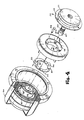
- Figure 4 is an exploded perspective view of the actuator and resolver, with parts in section of part of the actuator; and
- Figure 5A and Figure 5B are enlarged cross-sectional views showing an electromagnetic brake forming a part of the electric actuator.
- The present invention, as described herein, provides an electric actuator in combination with a resolver, for use in robotic arm systems, and is provided with provision for readily replacing the resolver, with an internal closed cycle air cooling system and with bearings providing support against wobbling and axial movement; an electromagnetic brake is also provided.
- Referring now to the drawings, Figure 1 is a perspective view of a lightweight electric
robotic actuator 10 in accordance with the present invention, comprising astationary housing 12 and arotary housing 100. A plurality ofbolts 101 extend fromhousing 100. Aresolver 110 extends fromhousing 100. - In the following discussion, in order to make the disclosure readily understandable, reference is made preliminarily to Figure 2, wherein those parts which are cross hatched in one direction are fixed relative to each other, and those parts which are cross hatched in the opposite direction are fixed relative to each other and rotate relative to the other parts. Thus, there is shown in Figure 2 an electric
robotic actuator 10 which includes astationary housing 12, having therewithin asupport 23 and an axially extending, stationaryhollow shaft 35. Arotary housing 100 is provided, which is generally in facing relationship tostationary housing 12, a hollowrotary shaft 70 extending from therotary housing 100, withball bearings 74 and 75 supporting the hollowrotary shaft 70 and hence therotary housing 100 on thestationary housing 12. An electric motor including a stator 34 androtor 52 is provided,rotor 52 being carried by arotor ring 50, journalled on thehollow shaft 35 bybearings harmonic drive mechanism 60 includes a stationary deep cupharmonic drive member 40, and serves to provide a speed reduction coupling between therotor ring 50 and therotary housing 100. Mounted onrotary housing 100 is aresolver 110, having a rotary shaft 122 which is rotatably supported byball bearings hollow shaft 131 of theresolver 110. - Referring now to Figure 3, the
stationary housing 12 has a back plate 13, and acylindrical portion 14. Back plate 13 is heat conductive and is provided with a plurality ofopenings 15, arranged in a circle, for receiving bolts 16. The back plate 13 is also provided with threaded bores 17 for attaching thestationary housing 12 to a suitable part of a robot, or other element. - The
cylindrical portion 14 is provided with a pair of lands 18a and 18b, located adjacent to the back plate 13 and adjacent to the open end thereof. At its outer end, thecylindrical portion 14 is provided with an outerperipheral groove 19 having aseal 20, and withinternal threads 21; the back plate 13, at its center, is provided with anopening 22. - Within the
stationary housing 12 there is provided asupport 23 including a peripherally extendingflange 24 having threaded openings 25 therein, in which are engaged the bolt 16. A radial flange 26 extends from theflange 24, havingbrake supporting screws 27 andbrake positioning screws 28 extending therethrough. Acylindrical portion 29 extends forwardly from the flange 26 having a plurality of radially extendingretaining screws 31 therein. In its end face, thecylindrical portion 29 has a threadedhole 32 for receiving a stator retaining screw 33 which extends through a stator 34 of a motor. - The
support 23 also includeshollow shaft 35 having a shoulder 36 against which are a pair of abutment rings 37. - A deep cup
harmonic drive member 40 is provided, having a back plate 41 and a cylindrical portion 42 having external splines 43 at its outer end, the back plate 41 having an air flow opening 44 therein. As will be understood, a circular array of the air flow openings 44 are provided in themember 40. Themember 40 is clamped between the inner face of the back plate 13 and thesupport 23 by the bolts 16. A plurality of radially extending passages 45 are provided in the interior of the back plate 13, and communicate with generally axially extendingpassages 46 through theflange 24;passage 46 is in registry with an opening 46a in themember 40. In this way, communication is had between a chamber outwardly of thecylindrical portion 29 ofsupport 23 and inwardly of the cylindrical portion 42 ofmember 40, on the one hand, and a chamber inwardly of thecylindrical portion 29, on the other hand. - The outer end of the
hollow shaft 35 is provided with external screw threads 35a. Anut 47 is threaded on the end ofhollow shaft 35, and engages the inner race of a ball bearing 48. Ball bearing 48 supports one end of arotor ring 50, the other end of which is supported by a ball bearing 49; the ball bearing 49 is engaged with a retaining ring 37, and shoulders on therotor ring 50 determine the positions ofball bearings - The
rotor ring 50 has spaced radial bosses 51, providing passages between them, the bosses supporting arotor 52 radially inwardly of stator 34. - Shown in Figure 4 is the deep cup
harmonic drive member 40 androtor 52, with therotor ring 50 extending therefrom.Rotor ring 50 has a pair ofkeyways 53 therein which receivekeys 54 of an Oldhamcoupling ring 55, havingkeys 56 on the face thereof opposite to that from which thekeys 54 extend. Thering 55 is provided with threadedholes 57 which receivebolts 58. Thekeys 54 engage in thekeyways 53, thereby effecting rotation of thecoupling ring 55, and thekeys 56 engage inkeyways 58 of anannular wave generator 59 forming a part of the harmonic drive unit. The holes 58a for thebolts 58 are somewhat larger in diameter than thebolts 58, so that thewave generator 59 is free to move in a limited manner on theseveral bolts 58. The Oldhamcoupling 55 provides for transmission of torque from therotor ring 50 to thewave generator 59, with provision for some misalignment between these parts. - The
wave generator 59 is part of aharmonic drive mechanism 60 driven by therotor ring 50, provided for transmitting rotary motion fromrotor 52 to therotary housing 100.Harmonic drive mechanism 60 comprises thewave generator 59, which is a drive member of the harmonic drive mechanism and has, in known fashion, an outside diameter of an elliptical configuration for generating a drive wave as thewave generator 59 is rotated about the axis ofhollow shaft 35 by therotor 52. A flexible ring 61 lies adjacent thewave generator 59, and a plurality of ball bearings 62 engage the ring 61, and an outer ring 63. The flexible drive provided by the rings 61 and 63 functions so that when thewave generator 59 is rotated, the elliptical configuration causes the inner flexible ring 61 and the outer flexible ring 63 to be flexed, thereby transmitting the elliptical wave generated bywave generator 59. The deep cupharmonic drive member 40 has external splines 42a on the cylindrical portion 42 on the outside thereof near its open end, radially outwardly of the ring 63. A rigid outer ring 64 has a spline 64a on the inner circumference thereof, which has teeth which mate with the teeth forming the splines 42a. Teeth of spline 64a are greater in number than teeth of spline 42a, so that these teeth will only mesh at two radially opposed points along their circumference, which points move along the circumference as outer ring 64 rotates about deep cupharmonic drive member 40. Since thewave generator 59 has an elliptical configuration, as it rotates, it causes the flexible ring 61 and flexible ring 63 to flex outwardly along the longest radius of thewave generator 59. The outward flexing of the outer ring 63 causes teeth of spline 42a of deep cupharmonic drive member 40 also to flex outwardly and into contact with the teeth of spline 64a. Because the teeth of splines 42a and 64a only mesh at two radially opposed points along their circumference, and since the rotation ofharmonic wave generator 59 causes the point of mesh to move along the circumference, this interaction causes outer ring 64 to rotate around deep cupharmonic drive member 40 in the same direction asharmonic wave generator 59, but at a slower angular speed. Theharmonic drive mechanism 60 thereby provides a means to transfer rotation from therotor 52 to the rigid outer ring 64 at a reduced speed. Thus, low speed, high torque movement can be transmitted in this manner with a relatively compact, lightweight mechanism. - Annular grease shield plates 82 and 82a are on either side of the inner ring 61, ball bearings 62 and outer ring 63 to protect the ball bearings 62.
- Circulation of air within the
actuator 10 is provided by a plurality offan blades 80 extending from anannular plate 81, having annular grease shield plate 82 adjacent to it,bolts 83 securing theannular plates 81 and 82 to thewave generator 59. Thus, theblades 80 rotate with thewave generator 59 androtor ring 52, driving air, as shown by the arrows, outwardly of the stator 34, between stator 34 and the cylindrical portion 42 of the deep cupharmonic drive member 40, and through the opening 44 in back plate 41 ofmember 40. The air there strikes against the heat conductive back plate 13 of thestationary housing 12, transferring heat to it, and becoming cool. The air then passes into the . radially extending passages 45 in back plate 13, through openings 46a inmember 40, and through axially extendingpassages 46 through theflange 24. The air then continues in its closed circuit, passing inwardly of therotor 52, between the radially spaced bosses 51, and then back to thefan blades 80, for recirculation. Thus, heat generated by thedrive mechanism 60, bearings, the electric motor and/ or other elements of the apparatus is dissipated. - Rigid outer ring 64 is provided with a plurality of axially extending openings 65, through each of which passes a
bolt 101 of lesser diameter than the opening 65.Bolt 101 is threaded into an opening 66 in a flange 67 on an end of hollowrotary shaft 70.Shaft 70 has a groove 71 near its end opposite the flange 67, in which are a pair of retaining rings 72: A pair of spaced lands 73a and 73b are located radially inwardly of the lands 18a and 18b, respectively, and a pair ofball bearings 74 and 75 are in engagement with these lands. Adjacent the flange 67, the rotaryhollow shaft 70 is provided with threads 76, being threadedly engaged by a nut 77, which is also engageable with the inner race of ball bearing 75. A cylindrical spacer 78 is provided between theball bearings 74 and 75, and a nut 79 is in threaded engagement with the threads of threadedopening 21 of thestationary housing 12. - The
bolt 101 passes through anopening 102 in therotary housing 100, and serves to clamp in assembled relationship thehollow shaft 70, the rigid outer ring 64 and therotary housing 100. Consequently, rotary motion imparted to the rigid outer ring 64 will effect rotation ofrotary housing 100, which will be supported not only by theharmonic drive mechanism 60 andhollow shaft 35, but also by the engagement ofhollow shaft 70 withball bearings 74 and 75 carried in thestationary housing 12. Due to the wide spacing of theball bearings 74 and 75, great stability is provided, so that the entire structure rotates accurately, while being of light weight. Not only wobbling motion is prevented, or significantly reduced, but in addition, axial movement is substantially eliminated. - The
rotary housing 100 comprises acylindrical portion 103 with anenlarged end 104, the interior of which is in sealing engagement with theseal 20 ingroove 19 ofstationary housing 12. - A
resolver 110 is associated with theactuator 10 extending into a cavity within it defined by such internal parts asharmonic drive 60 andshaft 35. Theresolver 110 is known in the art, being a variable transformer type of angular position sensor which is very accurate. The voltage outputs vary according to the angular position of the rotor and stator, both of which are toroidally wound.Resolver 110 includes a bell-shapedrotary housing 111 having anoutstanding flange 112 through which passfastening bolts 113 to secure therotary housing 111 to therotary housing 100, and concentrically with it. Thehousing 111 includescylindrical portion 114 which extends through an opening 105 centrally located inback plate 106 of therotary housing 100, and into a cavity within theactuator 10. On the interior ofback plate 115 ofrotary housing 111 there are secured, as by screws 116a and 116b,switches 117a and 117b; thecylindrical portion 114 ofrotary housing 111 carries on the interior thereof a winding 118, to which aconductor 119 is connected,conductor 119 being held in position by a retaining ring 120. - The
back plate 115 is provided at its central part with a threaded recess 115a, and extending from theback plate 115 is a hollow shaft 122 havingradial openings 123 therein, theconductor 119 passing through theopening 123 into the recess 116. The shaft 122, being integral withback plate 115, provides a firm base for the mounting of the entirerotary housing 111 by means of theball bearings actuator 10. - A pair of ball bearings are supported on the hollow shaft 122, and rotatably support rotary member 130 of
resolver 110. Rotary member 130 includes ahollow shaft 131, the interior of which is in engagement with the outer races of theball bearings Hollow shaft 131 is provided withradial openings 132, and is connected to asmaller diameter shaft 133, which is hollow, and to which is connected a collar 134, connected by a metal bellows 135 to acollar 136.Collar 136 has anenlarged end 137 with notches 137a, into which an anchoring pin 138 extends in mating, non-rotational relationship. The notches 137a ofcollar 137 are arranged in perpendicular planes, as shown in Figure 4. Pin 138 has its end extending into an opening 35a inhollow shaft 35. The metal bellows 135 provides elastic isolation of theresolver 110 from distortion due to stresses generated in the actuator. In addition, thebellows 135, which is of stainless steel, provides a zero backlash coupling which is elastically stiff in rotation, while remaining flexible in axial alignment, and acts as a compression spring to assure contact between the anchoring pin 138 and the notches 137a. - The
hollow shaft 131 carries a stator winding 141 which is radially inward of the rotor winding 118, and has a conductor 142 connected to it, conductor 142 extending through theopening 132, and thence through hollow shaft 122 into the recess 115a. - A
ring 143 mounted on the end ofhollow shaft 131 carries a pair of cam rings 144 and 145 for engagement with theswitches 117b and 117a, respectively. Cam rings 144 and 145 are modified split-type retainer rings, which are commercially available, and are formed as a flat helix. A camming notch is ground on the exterior surface of therings 144 and 145 and they are placed in position in grooves inring 143, being rotated to provide proper orientation. In the showing in Figure 3, the rollers of theswitches 117a and 117b will be seen to have entered into the notches in cam rings 144 and 145. - As shown in Figures 3, 5A and 5B, an electromagnetic brake is provided, comprising an
annular channel 85 carried onsupport 23 by the brake support screws 27, and having their position determined by brake positioning screws 28. Within thechannel 85 is acoil 86. An annularbrake shoe plate 87 is supported axially adjacent tocoil 86 andannular channel 85, and has an offsetactuator ring 88, spacedconnectors 89 extending generally axially, and connecting thebrake shoe plate 87 with theactuator ring 88; between theconnectors 89 are passages for the flow of air as hereinabove described. Abrake disc 90 is mounted onrotor ring 50, extending in a radial plane, between the annularbrake shoe plate 87 and abackup ring 91, which is held in position by the retaining screws 31 in thecylindrical portion 29 ofsupport 23.Springs 92 engage theactuator ring 88, urging the annularbrake shoe plate 87 against thebrake disc 90, and urging it against thebackup ring 91, in the braking position shown in Figure 5B. Thespring 92 is effective only when thecoil 86 is deenergized, since when it is supplied with current, its field draws thebrake shoe plate 87 to it, thus separating it from thebrake disc 90; Figure 5A shows the electromagnetic brake in the brake release position. - The
resolver 110 may be assembled to the electricrobotic actuator 10 as a unit, and accordingly may be removed therefrom, as a unit, and a replacement installed. This is accomplished by the above-described construction, in which theentire resolver 110 is assembled, being held together by the engagement of the races ofball bearings shafts 122 and 131, the assembledresolver 110 being inserted into the cavity in theactuator 10 so that the notches 137a in thecollar 137 engage and mate with the pin 138. Thecylindrical portion 114 of therotary housing 111 is caused to enter the opening 105 inrotary housing 100, andflange 112 is caused to engage the outer surface of theback plate 106, after which the openings for thebolts 113 are aligned, and thebolts 113 placed in position. - In order to assemble the rotatable and stationary parts of the
resolver 110, theswitches 117a and 117b may be provided with tapered rollers, to provide for axial movement between the rollers of the switches and the cam rings 144 and 145. This will permit the rollers of the switches to be depressed by rotating the cam rings slightly during the assembly operation.
Claims (9)
Applications Claiming Priority (2)
| Application Number | Priority Date | Filing Date | Title |
|---|---|---|---|
| US06/563,912 US4577127A (en) | 1983-12-21 | 1983-12-21 | Lightweight electric robotic actuator |
| US563912 | 1983-12-21 |
Publications (3)
| Publication Number | Publication Date |
|---|---|
| EP0146783A2 EP0146783A2 (en) | 1985-07-03 |
| EP0146783A3 EP0146783A3 (en) | 1985-12-04 |
| EP0146783B1 true EP0146783B1 (en) | 1989-08-02 |
Family
ID=24252394
Family Applications (1)
| Application Number | Title | Priority Date | Filing Date |
|---|---|---|---|
| EP84113998A Expired EP0146783B1 (en) | 1983-12-21 | 1984-11-20 | Improved lightweight electric robotic actuator |
Country Status (8)
| Country | Link |
|---|---|
| US (1) | US4577127A (en) |
| EP (1) | EP0146783B1 (en) |
| JP (1) | JPS60156238A (en) |
| KR (1) | KR850004413A (en) |
| CA (1) | CA1245267A (en) |
| DE (1) | DE3479274D1 (en) |
| ES (1) | ES8700812A1 (en) |
| ZA (1) | ZA849128B (en) |
Families Citing this family (70)
| Publication number | Priority date | Publication date | Assignee | Title |
|---|---|---|---|---|
| GB2164317A (en) * | 1984-09-15 | 1986-03-19 | Lamb Sceptre Ltd | Joint for a robotic arm |
| US4696378A (en) * | 1985-05-23 | 1987-09-29 | Houton Manufacturing Co., Inc. | Axially compact brake |
| DE3687092D1 (en) * | 1985-07-26 | 1992-12-17 | Mavilor Syst Sa | ELECTRIC MOTOR WITH DISC BRAKE. |
| US4678952A (en) * | 1985-08-13 | 1987-07-07 | Intelledex Incorporated | Sealed joint for a robot and the like |
| FI76898C (en) * | 1987-02-19 | 1988-12-12 | Antti Poro | ELECTRIC MOTOR. |
| FR2624669A1 (en) * | 1987-12-11 | 1989-06-16 | Banon Louis | Position detection device for electric motor |
| DE3805705C1 (en) * | 1988-02-24 | 1989-06-22 | Pfaff Haushaltmaschinen Gmbh, 7500 Karlsruhe, De | |
| US5018901A (en) * | 1988-07-21 | 1991-05-28 | Space Industries Partnership, L. P. | Ring latched coupler |
| US4955250A (en) * | 1989-06-08 | 1990-09-11 | The United States Of America As Represented By The United States Department Of Energy | Multiple forearm robotic elbow configuration |
| US5265667A (en) * | 1989-09-14 | 1993-11-30 | Westinghouse Electric Corp. | Robotic arm for servicing nuclear steam generators |
| IT219331Z2 (en) * | 1989-11-24 | 1993-02-22 | MODULAR TERMINAL BOARD BOX FOR APPLICATION ON ELECTRIC SERVO MOTORS FOR VALVE CONTROL. | |
| FR2681977B1 (en) * | 1991-09-30 | 1993-12-31 | Framatome | COOLING DEVICE ADAPTABLE TO A TELEMANIPULATOR AND ITS USE FOR INTERVENTION IN A HOSTILE ENVIRONMENT AT HIGH TEMPERATURE. |
| US5293107A (en) * | 1993-02-24 | 1994-03-08 | Fanuc Robotics North America, Inc. | Motorized rotary joint and method of constructing a modular robot utilizing same |
| AU3997595A (en) * | 1994-11-21 | 1996-06-17 | Stridsberg Innovation Ab | An electric motor layout |
| DE19522711C2 (en) * | 1995-06-22 | 1997-07-10 | Gildemeister Ag | Holding device for the workpiece spindle of a lathe |
| JP2004518096A (en) * | 2001-02-08 | 2004-06-17 | エクスラー アクチエンゲゼルシャフト | Wave transmission having a cap-shaped output ring |
| US6806595B2 (en) * | 2001-12-19 | 2004-10-19 | Applied Precision, Llc | Low backlash linear actuator |
| CN1515061B (en) * | 2002-04-01 | 2010-04-28 | 日产自动车株式会社 | Cooling structure of multi-shaft multi-layer rotary electric machine |
| SE524549C2 (en) * | 2002-07-09 | 2004-08-24 | Abb Ab | Device for an industrial robot |
| JP2007321879A (en) * | 2006-06-01 | 2007-12-13 | Harmonic Drive Syst Ind Co Ltd | Reduction gear unit with rotational position sensor |
| GB0616162D0 (en) | 2006-08-15 | 2006-09-20 | Whiteley Graham | Compact rotary actuator |
| DE102007013049A1 (en) * | 2007-03-19 | 2008-09-25 | Siemens Ag | Method for mounting an angle measuring device on an electric motor |
| DE102007017925A1 (en) * | 2007-04-13 | 2008-10-16 | Isel Automation Gmbh & Co. Kg | Rotational unit e.g. rotary unit, for use in e.g. milling machine, has outer ring of bearing unit removably connected with housing, and inner ring of bearing unit removably connected with stator or rotor of torque motor |
| DE102007019753A1 (en) * | 2007-04-20 | 2008-11-27 | Tschakarow, Sawa, Dr. | Electromechanical gripping device |
| DE102007029366A1 (en) * | 2007-06-26 | 2009-01-02 | Siemens Ag | Electric machine with simplified rotary encoder alignment |
| EP2136456B1 (en) | 2008-06-19 | 2012-09-12 | SICK STEGMANN GmbH | Component kit - servo motor |
| IT1394386B1 (en) * | 2008-09-29 | 2012-06-15 | Scuola Superiore Di Studi Universitari E Di Perfez | WOBBLE-TYPE ELECTROMAGNETIC STEP-BY-STEP MICROMOTOR |
| CN101659057B (en) * | 2009-09-18 | 2011-01-19 | 哈尔滨工业大学 | Lunar exploration mechanical arm modular joint with torque retention feature |
| PL2741982T3 (en) * | 2011-08-11 | 2017-05-31 | Mol Belting Systems, Inc. | Mounting face system |
| GB201114264D0 (en) | 2011-08-18 | 2011-10-05 | Touch Emas Ltd | Improvements in or relating to prosthetics and orthotics |
| US20130069450A1 (en) * | 2011-09-16 | 2013-03-21 | Persimmon Technologies, Corp. | Robot Drive With Passive Rotor |
| CN102626930B (en) * | 2012-04-28 | 2014-06-04 | 哈尔滨工业大学 | Mechanical arm modular joint with power-off brake and multiple perceptive functions |
| JP5617900B2 (en) * | 2012-11-19 | 2014-11-05 | 株式会社安川電機 | robot |
| GB201302025D0 (en) | 2013-02-05 | 2013-03-20 | Touch Emas Ltd | Improvements in or relating to prosthetics |
| US8888374B1 (en) * | 2013-05-08 | 2014-11-18 | Hiwin Technologies Corp. | Bearing with antiskid design |
| CN105246656B (en) * | 2013-05-17 | 2017-11-21 | 株式会社尼康 | Drive device and robot device |
| US9145919B2 (en) * | 2013-08-14 | 2015-09-29 | Mao-Tu Lee | Speed-reduction transmission bearing |
| WO2015120083A1 (en) | 2014-02-04 | 2015-08-13 | Rehabilitation Institute Of Chicago | Modular and lightweight myoelectric prosthesis components and related methods |
| GB201403265D0 (en) | 2014-02-25 | 2014-04-09 | Touch Emas Ltd | Prosthetic digit for use with touchscreen devices |
| GB201408253D0 (en) | 2014-05-09 | 2014-06-25 | Touch Emas Ltd | Systems and methods for controlling a prosthetic hand |
| DE102014222592A1 (en) * | 2014-09-08 | 2016-03-10 | Sms Group Gmbh | Drive a machine, torque motor, clutch device, device for processing materials and use of a torque motor |
| GB201417541D0 (en) | 2014-10-03 | 2014-11-19 | Touch Bionics Ltd | Wrist device for a prosthetic limb |
| CN105626722B (en) * | 2014-11-05 | 2018-02-09 | 广明光电股份有限公司 | The brake gear of robotic arm |
| CN105128029B (en) * | 2015-09-28 | 2017-02-01 | 哈尔滨工业大学深圳研究生院 | Modular high-torque space manipulator joint |
| US10415596B2 (en) * | 2016-03-24 | 2019-09-17 | United Technologies Corporation | Electric actuation for variable vanes |
| LU93045B1 (en) * | 2016-04-27 | 2017-11-07 | Ovalo Gmbh | Motorized joint for a programmable motion machine |
| LU93046B1 (en) * | 2016-04-27 | 2017-11-07 | Ovalo Gmbh | Motorized joint for a programmable motion machine |
| CN105743276B (en) * | 2016-04-29 | 2018-08-17 | 杭州通灵自动化股份有限公司 | A kind of few teeth difference speed reducer of built-in permanent magnet synchronous motor |
| CN106141666B (en) * | 2016-07-29 | 2018-03-16 | 柳州福能机器人开发有限公司 | The method for processing and assembling of intelligent nursing machine people's decelerator |
| US10369024B2 (en) | 2016-09-02 | 2019-08-06 | Touch Bionics Limited | Systems and methods for prosthetic wrist rotation |
| US11185426B2 (en) | 2016-09-02 | 2021-11-30 | Touch Bionics Limited | Systems and methods for prosthetic wrist rotation |
| US11571807B2 (en) | 2016-10-05 | 2023-02-07 | Robert Darby | Drive unit for robotic manipulators |
| IT201600106998A1 (en) * | 2016-10-24 | 2018-04-24 | N P C New Production Concept S R L | ROTATION DEVICE FOR A SUPPORT |
| US11161258B2 (en) * | 2017-01-16 | 2021-11-02 | Kollmorgen Corporation | Robot arm joint |
| DE102017211540A1 (en) * | 2017-07-06 | 2019-01-10 | Siemens Aktiengesellschaft | Geared motor unit |
| CN107825458A (en) * | 2017-09-13 | 2018-03-23 | 航天科工智能机器人有限责任公司 | A kind of integral joint device and mechanical arm |
| KR101983563B1 (en) | 2017-11-23 | 2019-05-29 | (주)한국미래기술 | Parallel type integrated actuator |
| KR101956617B1 (en) | 2017-11-23 | 2019-03-12 | (주)한국미래기술 | Parallel type integrated actuator |
| US10973660B2 (en) | 2017-12-15 | 2021-04-13 | Touch Bionics Limited | Powered prosthetic thumb |
| CN108406843B (en) * | 2018-05-29 | 2021-01-26 | 安徽工程大学 | Mechanical joint's connection structure |
| US10916993B2 (en) * | 2018-06-14 | 2021-02-09 | Raytheon Company | Method for heat transfer across rotary joint |
| CN110962158B (en) * | 2018-09-28 | 2021-09-17 | 台达电子工业股份有限公司 | Heat dissipation system of robot |
| CN111283657B (en) * | 2018-12-06 | 2021-12-24 | 台达电子工业股份有限公司 | Robot mechanism |
| JP7152615B2 (en) | 2019-09-25 | 2022-10-13 | ヤマハ発動機株式会社 | Articulated robots, single-axis robots and motor units |
| GB2588787A (en) * | 2019-11-06 | 2021-05-12 | Safran Electrical & Power | Static brake assembly |
| GB2588786A (en) * | 2019-11-06 | 2021-05-12 | Safran Electrical & Power | Static brake assembly |
| US11931270B2 (en) | 2019-11-15 | 2024-03-19 | Touch Bionics Limited | Prosthetic digit actuator |
| DE102020100271A1 (en) * | 2020-01-09 | 2021-07-15 | Bayerische Motoren Werke Aktiengesellschaft | Rotor position sensor and motor assembly |
| CN111409097B (en) * | 2020-04-01 | 2022-08-19 | 燕山大学 | Compact joint driving device for robot |
| CN111496838B (en) * | 2020-04-30 | 2022-06-07 | 北京理工大学 | Active heat dissipation joint and bionic robot comprising same |
Family Cites Families (9)
| Publication number | Priority date | Publication date | Assignee | Title |
|---|---|---|---|---|
| FR2126563A5 (en) * | 1971-02-10 | 1972-10-06 | Samm | |
| US4266152A (en) * | 1979-03-29 | 1981-05-05 | The Singer Company | Method of and apparatus for cooling electric motors and totally enclosed electric motors incorporating same |
| FR2465351A3 (en) * | 1979-09-07 | 1981-03-20 | Leroy Somer Moteurs | Immersible motor for motor-pump unit - has deflector at each end of motor stator, defining closed loop cooling route |
| DE2939160C3 (en) * | 1979-09-27 | 1982-03-18 | Siemens AG, 1000 Berlin und 8000 München | Setup with a resolver for radar antennas |
| IT7923154V0 (en) * | 1979-11-16 | 1979-11-16 | Setti Luciano | PERFECTED ELECTROMAGNETIC BRAKE, FOR SELF-BRAKING MOTORS, PROVIDED WITH MANUAL ADJUSTMENT OF THE CLEARANCE BETWEEN BRAKING PAD AND STILL. |
| JPH0119584Y2 (en) * | 1980-05-09 | 1989-06-06 | ||
| FR2482378A1 (en) * | 1980-05-09 | 1981-11-13 | Lorette Manufacture Vilebrequi | ROTOR WITH COOLING DEVICE, IN PARTICULAR COLLECTOR FOR ELECTRIC MOTORS, METHOD AND MEANS FOR CARRYING OUT THE SAME |
| JPS58165644A (en) * | 1982-03-26 | 1983-09-30 | Okuma Mach Works Ltd | Motor with position detector |
| US4398110A (en) * | 1982-05-05 | 1983-08-09 | Westinghouse Electric Corp. | Harmonic electric actuator |
-
1983
- 1983-12-21 US US06/563,912 patent/US4577127A/en not_active Expired - Lifetime
-
1984
- 1984-11-20 EP EP84113998A patent/EP0146783B1/en not_active Expired
- 1984-11-20 DE DE8484113998T patent/DE3479274D1/en not_active Expired
- 1984-11-22 ZA ZA849128A patent/ZA849128B/en unknown
- 1984-12-11 CA CA000469803A patent/CA1245267A/en not_active Expired
- 1984-12-19 JP JP59266541A patent/JPS60156238A/en active Granted
- 1984-12-19 ES ES538839A patent/ES8700812A1/en not_active Expired
- 1984-12-21 KR KR1019840008210A patent/KR850004413A/en not_active Application Discontinuation
Also Published As
| Publication number | Publication date |
|---|---|
| ZA849128B (en) | 1985-11-27 |
| US4577127A (en) | 1986-03-18 |
| ES8700812A1 (en) | 1986-10-16 |
| ES538839A0 (en) | 1986-10-16 |
| CA1245267A (en) | 1988-11-22 |
| JPH0235546B2 (en) | 1990-08-10 |
| JPS60156238A (en) | 1985-08-16 |
| EP0146783A3 (en) | 1985-12-04 |
| DE3479274D1 (en) | 1989-09-07 |
| KR850004413A (en) | 1985-07-15 |
| EP0146783A2 (en) | 1985-07-03 |
Similar Documents
| Publication | Publication Date | Title |
|---|---|---|
| EP0146783B1 (en) | Improved lightweight electric robotic actuator | |
| CA1190581A (en) | Harmonic electric actuator | |
| KR100676646B1 (en) | Permanent magnet coupler with adjustable air gaps | |
| US6701803B1 (en) | Reduction gears-integrated actuator | |
| EP0225616B1 (en) | Electric motor | |
| EP2479871B1 (en) | Electrical machines | |
| US5982066A (en) | Electric motor | |
| JP2003194071A (en) | Bearing | |
| EP0780955B1 (en) | Actuator | |
| US20170082115A1 (en) | Electric supercharger | |
| EP3460282B1 (en) | Electric linear motion actuator | |
| US4560895A (en) | Electric motor equipped with inner blocking brake | |
| JP4188526B2 (en) | Device for locking and securing cylindrical small members together in the axial and radial directions | |
| WO2002075906A2 (en) | Adjustable magnetic coupler | |
| JPS6231211B2 (en) | ||
| GB2122035A (en) | Improvements to electric retarders | |
| US5019734A (en) | Brake coupler for displacement-type armature motor | |
| JPH0526233A (en) | Roller bearing in which position of information pickup can be adjusted | |
| CN111615602A (en) | Strain wave gear | |
| EP4064524A1 (en) | Electric tool, electric motor and rotor assembly thereof | |
| US5855264A (en) | Vehicle transmission system fitted with an electrical retarder | |
| US5847481A (en) | Vehicle transmission system fitted with an electrical retarder | |
| CN112491246A (en) | Magnetic adjusting ring component, magnetic gear, corresponding assembling method and composite motor | |
| CN219417838U (en) | Focusing device for optical lens | |
| US11626788B1 (en) | Magnetic cycloidal gear assembly including mounting arrangement and adjustable counterweight |
Legal Events
| Date | Code | Title | Description |
|---|---|---|---|
| PUAI | Public reference made under article 153(3) epc to a published international application that has entered the european phase |
Free format text: ORIGINAL CODE: 0009012 |
|
| AK | Designated contracting states |
Designated state(s): BE CH DE FR GB IT LI SE |
|
| PUAL | Search report despatched |
Free format text: ORIGINAL CODE: 0009013 |
|
| AK | Designated contracting states |
Designated state(s): BE CH DE FR GB IT LI SE |
|
| 17P | Request for examination filed |
Effective date: 19860520 |
|
| 17Q | First examination report despatched |
Effective date: 19870731 |
|
| ITF | It: translation for a ep patent filed |
Owner name: UFFICIO BREVETTI RICCARDI & C. |
|
| GRAA | (expected) grant |
Free format text: ORIGINAL CODE: 0009210 |
|
| AK | Designated contracting states |
Kind code of ref document: B1 Designated state(s): BE CH DE FR GB IT LI SE |
|
| REF | Corresponds to: |
Ref document number: 3479274 Country of ref document: DE Date of ref document: 19890907 |
|
| ET | Fr: translation filed | ||
| PLBE | No opposition filed within time limit |
Free format text: ORIGINAL CODE: 0009261 |
|
| STAA | Information on the status of an ep patent application or granted ep patent |
Free format text: STATUS: NO OPPOSITION FILED WITHIN TIME LIMIT |
|
| 26N | No opposition filed | ||
| PGFP | Annual fee paid to national office [announced via postgrant information from national office to epo] |
Ref country code: FR Payment date: 19910917 Year of fee payment: 8 |
|
| PGFP | Annual fee paid to national office [announced via postgrant information from national office to epo] |
Ref country code: SE Payment date: 19910919 Year of fee payment: 8 |
|
| PGFP | Annual fee paid to national office [announced via postgrant information from national office to epo] |
Ref country code: GB Payment date: 19910924 Year of fee payment: 8 |
|
| PGFP | Annual fee paid to national office [announced via postgrant information from national office to epo] |
Ref country code: BE Payment date: 19911118 Year of fee payment: 8 |
|
| ITTA | It: last paid annual fee | ||
| PGFP | Annual fee paid to national office [announced via postgrant information from national office to epo] |
Ref country code: CH Payment date: 19911216 Year of fee payment: 8 |
|
| PGFP | Annual fee paid to national office [announced via postgrant information from national office to epo] |
Ref country code: DE Payment date: 19911231 Year of fee payment: 8 |
|
| PG25 | Lapsed in a contracting state [announced via postgrant information from national office to epo] |
Ref country code: GB Effective date: 19921120 |
|
| PG25 | Lapsed in a contracting state [announced via postgrant information from national office to epo] |
Ref country code: SE Effective date: 19921121 |
|
| PG25 | Lapsed in a contracting state [announced via postgrant information from national office to epo] |
Ref country code: LI Effective date: 19921130 Ref country code: CH Effective date: 19921130 Ref country code: BE Effective date: 19921130 |
|
| BERE | Be: lapsed |
Owner name: WESTINGHOUSE ELECTRIC CORP. Effective date: 19921130 |
|
| GBPC | Gb: european patent ceased through non-payment of renewal fee |
Effective date: 19921120 |
|
| PG25 | Lapsed in a contracting state [announced via postgrant information from national office to epo] |
Ref country code: FR Effective date: 19930730 |
|
| REG | Reference to a national code |
Ref country code: CH Ref legal event code: PL |
|
| PG25 | Lapsed in a contracting state [announced via postgrant information from national office to epo] |
Ref country code: DE Effective date: 19930803 |
|
| REG | Reference to a national code |
Ref country code: FR Ref legal event code: ST |
|
| EUG | Se: european patent has lapsed |
Ref document number: 84113998.3 Effective date: 19930610 |