EP0146336A2 - Steckverbindung - Google Patents
Steckverbindung Download PDFInfo
- Publication number
- EP0146336A2 EP0146336A2 EP84308628A EP84308628A EP0146336A2 EP 0146336 A2 EP0146336 A2 EP 0146336A2 EP 84308628 A EP84308628 A EP 84308628A EP 84308628 A EP84308628 A EP 84308628A EP 0146336 A2 EP0146336 A2 EP 0146336A2
- Authority
- EP
- European Patent Office
- Prior art keywords
- stab
- socket member
- end portion
- mandrel
- collet finger
- Prior art date
- Legal status (The legal status is an assumption and is not a legal conclusion. Google has not performed a legal analysis and makes no representation as to the accuracy of the status listed.)
- Withdrawn
Links
- 230000015572 biosynthetic process Effects 0.000 claims abstract description 28
- 238000003780 insertion Methods 0.000 claims abstract description 4
- 230000037431 insertion Effects 0.000 claims abstract description 4
- 239000012530 fluid Substances 0.000 claims description 9
- 230000000149 penetrating effect Effects 0.000 claims description 2
- 230000035515 penetration Effects 0.000 claims description 2
- 238000005755 formation reaction Methods 0.000 abstract 4
- 230000009189 diving Effects 0.000 description 11
- XLYOFNOQVPJJNP-UHFFFAOYSA-N water Substances O XLYOFNOQVPJJNP-UHFFFAOYSA-N 0.000 description 6
- 239000004020 conductor Substances 0.000 description 4
- 229910000831 Steel Inorganic materials 0.000 description 3
- 239000010959 steel Substances 0.000 description 3
- 230000000712 assembly Effects 0.000 description 2
- 238000000429 assembly Methods 0.000 description 2
- 230000008878 coupling Effects 0.000 description 2
- 238000010168 coupling process Methods 0.000 description 2
- 238000005859 coupling reaction Methods 0.000 description 2
- 230000005611 electricity Effects 0.000 description 2
- 239000000725 suspension Substances 0.000 description 2
- 238000004140 cleaning Methods 0.000 description 1
- 230000006835 compression Effects 0.000 description 1
- 238000007906 compression Methods 0.000 description 1
- 230000000694 effects Effects 0.000 description 1
- 238000007689 inspection Methods 0.000 description 1
- 239000000463 material Substances 0.000 description 1
- 238000012986 modification Methods 0.000 description 1
- 230000004048 modification Effects 0.000 description 1
- 230000004083 survival effect Effects 0.000 description 1
Images


Classifications
-
- F—MECHANICAL ENGINEERING; LIGHTING; HEATING; WEAPONS; BLASTING
- F16—ENGINEERING ELEMENTS AND UNITS; GENERAL MEASURES FOR PRODUCING AND MAINTAINING EFFECTIVE FUNCTIONING OF MACHINES OR INSTALLATIONS; THERMAL INSULATION IN GENERAL
- F16B—DEVICES FOR FASTENING OR SECURING CONSTRUCTIONAL ELEMENTS OR MACHINE PARTS TOGETHER, e.g. NAILS, BOLTS, CIRCLIPS, CLAMPS, CLIPS OR WEDGES; JOINTS OR JOINTING
- F16B21/00—Means for preventing relative axial movement of a pin, spigot, shaft or the like and a member surrounding it; Stud-and-socket releasable fastenings
- F16B21/10—Means for preventing relative axial movement of a pin, spigot, shaft or the like and a member surrounding it; Stud-and-socket releasable fastenings by separate parts
-
- B—PERFORMING OPERATIONS; TRANSPORTING
- B63—SHIPS OR OTHER WATERBORNE VESSELS; RELATED EQUIPMENT
- B63B—SHIPS OR OTHER WATERBORNE VESSELS; EQUIPMENT FOR SHIPPING
- B63B21/00—Tying-up; Shifting, towing, or pushing equipment; Anchoring
- B63B21/56—Towing or pushing equipment
- B63B21/58—Adaptations of hooks for towing; Towing-hook mountings
- B63B21/60—Quick releases
-
- B—PERFORMING OPERATIONS; TRANSPORTING
- B63—SHIPS OR OTHER WATERBORNE VESSELS; RELATED EQUIPMENT
- B63C—LAUNCHING, HAULING-OUT, OR DRY-DOCKING OF VESSELS; LIFE-SAVING IN WATER; EQUIPMENT FOR DWELLING OR WORKING UNDER WATER; MEANS FOR SALVAGING OR SEARCHING FOR UNDERWATER OBJECTS
- B63C11/00—Equipment for dwelling or working underwater; Means for searching for underwater objects
- B63C11/34—Diving chambers with mechanical link, e.g. cable, to a base
Definitions
- This invention relates to a stab connector assembly.
- a stab connector assembly comprising a socket member having a first locking formation on its side wall, and a stab member for penetrating the socket member and having a second locking formation engageable with the first locking formation to resist withdrawal of the stab member from the socket member, the first or second locking formation being provided on at least one collet finger secured at one end portion and deflectable about that end portion so that the locking formation on the collet finger can be moved between a first position in which it can pass the other locking formation on penetration of the stab member into the socket member and a second position in which it extends radially to engage the other locking formation.
- a number of collet fingers are preferably provided around the stab member to provide the second locking formation and to be engageable with a shoulder formed around the inside wall of the socket member, the shoulder providing the first locking formation.
- the collet fingers preferably are deflectable by means of the resilience of the material of which they are made, so that they can be rigidly fixed at one end without any movable joints being used.
- the stab member may have a central mandrel and the collet finger or fingers may extend along the mandrel and be movable, for example slidable, longitudinally of it.
- the mandrel may have a shoulder which is engageable with a corresponding face on the free end portion of the collet finger in a manner whereby a force applied in use to the mandrel in a direction tending to retract it from the socket member causes the free end portion of the collet finger to be wedged or otherwise trapped between the mandrel shoulder and the first locking formation on the socket member. The free end portion of the collet finger is then subject to compression between the mandrel and first locking formation.
- the free end portion of the collet finger has a rearwardly-directed face for engagement with a corresponding forwardly-directed face on the socket member, said forwardly-directed face forming the first locking formation, said rearwardly-directed face on the collet finger being disposed at an angle of from 10 degrees to 60 degrees to the direction of insertion of the stab member into the socket member.
- the stab member may have one or more through bores or electrical conductors for communication with corresponding apertures or conductors in the socket member so that fluid can be passed from the stab member to the socket member.
- the collet finger will be provided on the side wall of the stab member, but in some cases the collet finger may be on the inside wall of the socket member.
- the stab member for use in the assembly of the invention may comprise an elongate member having a collet finger on its side wall, the collet finger being held on the elongate member at one end portion and having at its free end portion a locking formation directed for preventing retraction of the elongate member from a socket member, the collet finger being deflectable at its free end radially of the elongate member.
- the stab member may be releasable from the socket, for example if the assembly, or at least the stab member, is to be re-used.
- the collet finger may have a length greater than the distance from the first locking formation of the socket member to the mouth of the socket, so that when the stab member is engaged within the socket the collet finger is accessible from outside the socket member.
- the collet finger may have a shoulder at its secured end portion outside the socket member so that a force may be exerted on it to move it relative to the mandrel and thereby allow it to disengage from the mandrel and move to a reduced-diameter portion of the mandrel where it can deflect and allow the mandrel to be retracted from the socket.
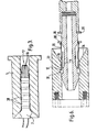
- the stab connector assembly of this embodiment of the invention has a socket member in the form of a steel tube 1 which is secured to a bracket 2 on a body such for example as a diving bell by means of a universal joint pivotal about axes 3 and 4.
- the tube 1 has an inwardly-chamfered outer end 5 and a shoulder 6 formed by a step in its inner wall.
- a steel stab member 7 is connected by a screw thread coupling 8 to a wire lifting cable 9 capable of bearing the weight of the diving bell and extending from the surface of the water, and is in the form of a central mandrel 10 having an annular recess 11 which has an inclined forward wall 12.
- the mandrel terminates in a head portion 13 having a rearwardly-directed shoulder 14.
- a steel sleeve 15 freely slidable longitudinally of the mandrel 10, the sleeve being slit from its forward end to form collet fingers 16 each terminating in a head 17 having a forwardly-directly abutment face 18 engageable with the shoulder 14 of the mandrel 10.
- the head 17 has a rearwardly-directed abutment face 19 engageable with the shoulder 6 of the tube 1.
- the collet fingers 16 are of selected thickness to allow them to be resiliently deflectable towards the axis of the mandrel 10 so that, when the head 17 is disposed at the recess 11 and pressed inwardly the fingers 16 deflect to allow the head 17 to enter the recess 11.
- the stab member In use for connecting the lifting cable 9 to the diving bell, the stab member is pushed into the tube 1 whereby the heads 17 of the fingers 16 engage the chamfered end 5, causing the sleeve 15 to slide rearwardly along the mandrel 10 until the heads 17 are adjacent the recess 11. The chamfer then pushes the heads 17 into the recess 11, deflecting the fingers 16, and allowing the stab member 7 to pass along the tube 1.
- the assembly is for connecting fluid pipelines from the surface of the water in a body such as a diving bell, rather than for use in lifting a bell as in Fig. 1.
- the shoulder 6 and faces 19 are less pronounced and provide a releasable connection for the stab member 7 to the tube 1.
- the collet fingers 16 extend from a sleeve 15 which is screwed directly to a supply line 20 having a through bore 21 for hot water and a through bore 22 for breathable diving gas.
- the tube 1 has corresponding bores 23, 24 respectively for feeding the fluids into the diving bell.
- Fluid seals 25 are provided on the stab member 7 and no central mandrel is present as the connection does not need to be load-bearing; indeed, the bores 21 and 22 terminate radially of the stab member 7 so that the fluid flow does not produce a net force on the stab member into or out of the tube 1.
- the tube 1 in this case has an annular projection 26 engaging with an annular recess 27 in the stab member 7 wall to locate the stab member precisely at the required location within the tube 1 to provide the fluid connection.
- the tube 1 is rigidly secured on the diving bell.
- Fig. 3 the assembly is similar to that of Fig. 2 but is for transferring electricity to a body such as a diving bell.
- the body of the stab member 7 has annular conductor bands 28 electrically connected to a power supply at the surface and corresponding with conductors (not shown) exposed at the inside wall of the tube 1.
- the assemblies of these embodiments provide rapid and effective life-saving systems for a stranded diving bell or other underwater vehicle or structure.
- the stab members 7 of Figs. 2 and 3 can be easily attached by divers or remotely-operated vehicles to tubes 1 already provided on the bell, and hot water, breathable gas and electricity supplied from the surface. This provides the occupants of the bell with the capability of survival for a long period.
- the stab member 7 of Fig. 1 can then be connected to the tube 2 secured to the bell, and the bell lifted safely to the surface.
- the sleeve 15 and collet fingers 16 extend from a ring 30 which is slidably mounted on the mandrel 10, and an annular recess 31 of the tube 1 engaging with the heads 17 of the collet fingers 16 is spaced from the tube's outer end by a distance less than the distance between the ring 30 and the heads 17.
- An annular shoulder 35 is rigidly fixed on the mandrel 10 rearwardly of the collet fingers 16.
- the connector of Fig. 6 can be engaged in similar manner to that of Figs. 1 and 4 with the heads 17 in the recess 31, but when in position the ring 30 is external of the tube 1, as shown. (It will be appreciated that the ring 30 could be disposed in the chamfered portion 34 of the tube 1, so long as it is accessible from outside the tube 1). If it is desired to break the connection and recover the mandrel 10, hydraulic jaws (not shown) are applied to the ring 30 and the shoulder 35 and actuated to force the ring 30 and shoulder 35 together.
- connection for ROV's to hold themselves on underwater structures and also to "plug in” to alternative selected cleaning, inspection, hydraulic fluid supply or other work packages for use on such structures.
- assembly of Fig. 6 may be used, with the mandrel 10 being externally powered to engage or release the connection.
Landscapes
- Engineering & Computer Science (AREA)
- Mechanical Engineering (AREA)
- Ocean & Marine Engineering (AREA)
- General Engineering & Computer Science (AREA)
- Chemical & Material Sciences (AREA)
- Combustion & Propulsion (AREA)
- Adornments (AREA)
- Coupling Device And Connection With Printed Circuit (AREA)
- Battery Mounting, Suspending (AREA)
- Details Of Connecting Devices For Male And Female Coupling (AREA)
- Quick-Acting Or Multi-Walled Pipe Joints (AREA)
Applications Claiming Priority (4)
| Application Number | Priority Date | Filing Date | Title |
|---|---|---|---|
| GB838333663A GB8333663D0 (en) | 1983-12-16 | 1983-12-16 | Stab connector assembly |
| GB8333663 | 1983-12-16 | ||
| GB848416999A GB8416999D0 (en) | 1984-07-04 | 1984-07-04 | Stab connector assembly |
| GB8416999 | 1984-07-04 |
Publications (2)
| Publication Number | Publication Date |
|---|---|
| EP0146336A2 true EP0146336A2 (de) | 1985-06-26 |
| EP0146336A3 EP0146336A3 (de) | 1987-10-14 |
Family
ID=26287117
Family Applications (1)
| Application Number | Title | Priority Date | Filing Date |
|---|---|---|---|
| EP84308628A Withdrawn EP0146336A3 (de) | 1983-12-16 | 1984-12-12 | Steckverbindung |
Country Status (3)
| Country | Link |
|---|---|
| EP (1) | EP0146336A3 (de) |
| DK (1) | DK601684A (de) |
| NO (1) | NO845052L (de) |
Cited By (3)
| Publication number | Priority date | Publication date | Assignee | Title |
|---|---|---|---|---|
| GB2198177A (en) * | 1986-10-10 | 1988-06-08 | Michael Squires | Coupling device |
| WO2008043823A1 (fr) * | 2006-10-13 | 2008-04-17 | Thales | Dispositif pour l'arrimage et le desarrimage automatique d'un emetteur sonar remorque a une ligne de remorquage d'un sonar actif. |
| US9309739B2 (en) | 2013-11-19 | 2016-04-12 | David Wright | Stab connector assembly and methods usable for establishing a fluid connection |
Family Cites Families (2)
| Publication number | Priority date | Publication date | Assignee | Title |
|---|---|---|---|---|
| FR2169464A5 (de) * | 1972-01-26 | 1973-09-07 | Matra Engins | |
| FR2155706A5 (de) * | 1972-10-17 | 1973-05-18 | Subsea Equipment Ass Ltd |
-
1984
- 1984-12-12 EP EP84308628A patent/EP0146336A3/de not_active Withdrawn
- 1984-12-14 NO NO845052A patent/NO845052L/no unknown
- 1984-12-14 DK DK601684A patent/DK601684A/da not_active Application Discontinuation
Cited By (6)
| Publication number | Priority date | Publication date | Assignee | Title |
|---|---|---|---|---|
| GB2198177A (en) * | 1986-10-10 | 1988-06-08 | Michael Squires | Coupling device |
| GB2198177B (en) * | 1986-10-10 | 1991-01-16 | Michael Squires | Coupling device |
| WO2008043823A1 (fr) * | 2006-10-13 | 2008-04-17 | Thales | Dispositif pour l'arrimage et le desarrimage automatique d'un emetteur sonar remorque a une ligne de remorquage d'un sonar actif. |
| FR2907263A1 (fr) * | 2006-10-13 | 2008-04-18 | Thales Sa | Dispositif pour l'arrimage et le desarrimage automatique d'un emetteur sonar remorque a une ligne de remorquage d'un sonar actif. |
| US8104419B2 (en) | 2006-10-13 | 2012-01-31 | Thales | Device for automatically attaching and detaching a towed sonar transmitter to and from an active-sonar tow line |
| US9309739B2 (en) | 2013-11-19 | 2016-04-12 | David Wright | Stab connector assembly and methods usable for establishing a fluid connection |
Also Published As
| Publication number | Publication date |
|---|---|
| EP0146336A3 (de) | 1987-10-14 |
| NO845052L (no) | 1985-06-17 |
| DK601684D0 (da) | 1984-12-14 |
| DK601684A (da) | 1985-06-17 |
Similar Documents
| Publication | Publication Date | Title |
|---|---|---|
| US5984006A (en) | Emergency release tool | |
| US4682913A (en) | Hydraulic stab connector | |
| US9546527B2 (en) | Wet connection system for downhole equipment | |
| EP1129271B1 (de) | Abschereinrichtung für unterwasserhilsleitungen | |
| US8485837B2 (en) | Electrical wet connector in downhole environment | |
| CN101356693B (zh) | 用于水下服务线路的连接装置 | |
| WO2019232605A1 (pt) | Sistema de acoplamento entre um enrijecedor de curvatura e uma boca de sino compreendendo uma pluralidade de mecanismos de travamento | |
| US5306050A (en) | Apparatus for internally connecting to coiled tubing | |
| ES2374472T3 (es) | Sujeción de cables. | |
| US4073562A (en) | Wet connector | |
| EP3137725B1 (de) | Verriegelbarer steckverbinderbehälter | |
| US2971178A (en) | Flexible connector for conductor core cable | |
| EP0146336A2 (de) | Steckverbindung | |
| BR112015032165B1 (pt) | Conexão submarina e método para conectar um umbilical a uma estrutura submarina utilizando uma conexão submarina | |
| US3931670A (en) | Apparatus and method for connecting two axially spaced apart pipes | |
| CN208966226U (zh) | 用于水平井输送牵引器射孔工具的丢手短节 | |
| CN110416804B (zh) | 一种用于井下电缆连接的湿接头 | |
| CN104227386A (zh) | 改进的水下快速连接数个接头的装置 | |
| JPH01157077A (ja) | 多芯ケーブルと吊下すべきゾンデとを機械的/電気的に接続する接続器 | |
| US20060003626A1 (en) | Cable connection | |
| US6530794B2 (en) | Coupler | |
| JP2025541118A (ja) | 可動海中構造物の海中エンドフィッティングの緊急分離のためのコネクタ組立体 | |
| GB2216972A (en) | Umbilical connectors | |
| CN217545546U (zh) | 一种通信线路铺设用保护罩 | |
| CN210092459U (zh) | 井下电缆连接用接头组件 |
Legal Events
| Date | Code | Title | Description |
|---|---|---|---|
| PUAI | Public reference made under article 153(3) epc to a published international application that has entered the european phase |
Free format text: ORIGINAL CODE: 0009012 |
|
| AK | Designated contracting states |
Designated state(s): BE DE FR GB NL SE |
|
| PUAL | Search report despatched |
Free format text: ORIGINAL CODE: 0009013 |
|
| AK | Designated contracting states |
Kind code of ref document: A3 Designated state(s): BE DE FR GB NL SE |
|
| 17P | Request for examination filed |
Effective date: 19880408 |
|
| 17Q | First examination report despatched |
Effective date: 19890630 |
|
| STAA | Information on the status of an ep patent application or granted ep patent |
Free format text: STATUS: THE APPLICATION IS DEEMED TO BE WITHDRAWN |
|
| 18D | Application deemed to be withdrawn |
Effective date: 19891113 |