EP0146180B1 - Mit Getränkeabgabevorrichtung versehene Kühlschranktür - Google Patents
Mit Getränkeabgabevorrichtung versehene Kühlschranktür Download PDFInfo
- Publication number
- EP0146180B1 EP0146180B1 EP84201785A EP84201785A EP0146180B1 EP 0146180 B1 EP0146180 B1 EP 0146180B1 EP 84201785 A EP84201785 A EP 84201785A EP 84201785 A EP84201785 A EP 84201785A EP 0146180 B1 EP0146180 B1 EP 0146180B1
- Authority
- EP
- European Patent Office
- Prior art keywords
- pipe
- door
- compartment
- container
- slide
- Prior art date
- Legal status (The legal status is an assumption and is not a legal conclusion. Google has not performed a legal analysis and makes no representation as to the accuracy of the status listed.)
- Expired
Links
- 238000005192 partition Methods 0.000 claims description 15
- 239000007788 liquid Substances 0.000 claims description 5
- 239000000463 material Substances 0.000 description 3
- 229920003023 plastic Polymers 0.000 description 3
- 239000004033 plastic Substances 0.000 description 3
- 238000010276 construction Methods 0.000 description 2
- 230000015572 biosynthetic process Effects 0.000 description 1
- 230000003670 easy-to-clean Effects 0.000 description 1
- 239000013013 elastic material Substances 0.000 description 1
- 238000011065 in-situ storage Methods 0.000 description 1
- 239000011810 insulating material Substances 0.000 description 1
- 230000007774 longterm Effects 0.000 description 1
- 238000000034 method Methods 0.000 description 1
- 238000005057 refrigeration Methods 0.000 description 1
- 230000000717 retained effect Effects 0.000 description 1
- 238000007789 sealing Methods 0.000 description 1
Images


Classifications
-
- B—PERFORMING OPERATIONS; TRANSPORTING
- B67—OPENING, CLOSING OR CLEANING BOTTLES, JARS OR SIMILAR CONTAINERS; LIQUID HANDLING
- B67D—DISPENSING, DELIVERING OR TRANSFERRING LIQUIDS, NOT OTHERWISE PROVIDED FOR
- B67D3/00—Apparatus or devices for controlling flow of liquids under gravity from storage containers for dispensing purposes
- B67D3/0009—Apparatus or devices for controlling flow of liquids under gravity from storage containers for dispensing purposes provided with cooling arrangements
-
- B—PERFORMING OPERATIONS; TRANSPORTING
- B67—OPENING, CLOSING OR CLEANING BOTTLES, JARS OR SIMILAR CONTAINERS; LIQUID HANDLING
- B67D—DISPENSING, DELIVERING OR TRANSFERRING LIQUIDS, NOT OTHERWISE PROVIDED FOR
- B67D3/00—Apparatus or devices for controlling flow of liquids under gravity from storage containers for dispensing purposes
-
- F—MECHANICAL ENGINEERING; LIGHTING; HEATING; WEAPONS; BLASTING
- F25—REFRIGERATION OR COOLING; COMBINED HEATING AND REFRIGERATION SYSTEMS; HEAT PUMP SYSTEMS; MANUFACTURE OR STORAGE OF ICE; LIQUEFACTION SOLIDIFICATION OF GASES
- F25D—REFRIGERATORS; COLD ROOMS; ICE-BOXES; COOLING OR FREEZING APPARATUS NOT OTHERWISE PROVIDED FOR
- F25D23/00—General constructional features
- F25D23/12—Arrangements of compartments additional to cooling compartments; Combinations of refrigerators with other equipment, e.g. stove
- F25D23/126—Water cooler
Definitions
- the invention relates to a refrigerator door with a drink dispenser.
- a drink dispenser built-in in a door of a refrigerator is for example known from US-A-3 476 295.
- a container of the dispenser is detachably arranged at the inside of the door.
- the door comprises a compartment which is accessible from the outside for taking a drink by means of a discharge tube.
- the dischargetube is closely fixed in an opening in a wall of the compartment and is provided with a valve. For refilling the container, this must be removed whereas the discharge tube remains in situ. This leads to filthiness of the tube and the valve which are difficult to clean, especially if the drink contains sugar or other syrup-like solutions. In the long term these valves also become unreliable due to the formation of deposits between movable and sealing parts.
- the tube or pipe remains fixed to the container during filling thereof.
- the opening in the wall of the compartment must be relatively large resulting in cold leakage from the inside of the refrigerator.
- the discharge pipe is not provided with a valve or tap.
- the object of the invention is to provide a refrigerator door with a drink dispenser which dispenser is easy to clean, reliable and simple in operation and which limits leakage of cold from the inside of the refrigerator to a minimum.
- a refrigerator door with a drink dispenser comprising inner and outer panels forming the wall of the door, the drink dispenser comprising a container which is detachable arranged on the inner panel, delivery means for the drink comprising a pipe which communicates with the interior of the container, the door further comprising a compartment which is accessible from the outside of the refrigerator without opening the door, the pipe extending through an opening in a wall of said compartment terminating in a spout located in said compartment, characterized in that
- a drink dispenser which comprises a container with a discharge pipe which is hingedly movable from an inoperative position, in which the spout is positioned above a maximum liquid level in the container, to a delivery position.
- this drink dispenser is entirely placed on a shelf inside the refrigerator cabinet.
- the refrigerator doors For taking a drink the refrigerator doors must be opened which results in cold leakage.
- the present invention starts from another construction of a drink dispenser, namely one which is accessible from the outside in orderto take a drinkwithout opening the refrigerator door.
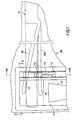
- the reference numeral 100 indicates a refrigerator door, 101 a drink dispenser container and 108 a delivery pipe which is hingedly connected at one end to said container and which, either by an inherent resilience or by the action of a spring or other elastic means between the container and the pipe, tends to assume a raised inoperative position.
- the refrigerator door comprises inner and outer panels 102 and 103, between which an insulating material is disposed.
- the container 101 rests on a shelf 106 formed on the inner side of the refrigerator door 100.
- Reference numeral 104 indicates the side walls of the refrigerator casing and 105 the refrigeration compartment.
- the container 101 is provided at its end with bosses or projections 109 which, by virtue of the elastic deformability of the materials used, engage in corresponding seats provided in shoulders 110 at the ends of the shelf 106.
- a compartment 111 which has an opening 113 at the front through which the user can insert a cup 112 into the compartment 111 to be filled with drink from the container 101.
- a button 114 which can be slid downwards by the user in the direction of the arrow F.
- a slide 116 slidable in vertical guides 130 and 131 is formed with a recess 125 in which the face end of the pipe 108 is located in such a way that this end is retained between the upper and lower edges of the recess.
- the button 114 comprises a projection 117 which is fixed in a recess in the slide 116.
- the projection 117 extends through a vertical slot 118 in a profiled indicator plate 119 which closes a compartment 120 in which the slide 116 is vertically movable, this compartment being provided in the door adjacent the compartment 111 for the cup.
- compartment 111 is divided into a lower compartment 111A, in which a cup can be placed, and an upper compartment 111 B, in which a spout 107 of the pipe 108 is located, by means of a pivotable partition 124 (see Figure 4).
- a pivotable partition 124 Extending down one side of the slide 116 is a lug 121 which co-operates with a radial projection 122 on the pivot spindle 123 of the pivotable partition 124.
- the guides 130 and 131 for the slide 116 are formed by part of a profiled member 132, which may comprise a plurality of parts and which at least partly defines the compartments 111 and 120, and by part of the indicator plate 119 respectively.
- the spindle 123 of the partition 124 is rotatably supported in the member 132.
- the inner panel 102 and the member 132 comprise openings 140 and 141 through which the pipe 108 passes.
- the slide 116 is formed at the front end with a downwardly directed tab 150 which closes the slot 118 in which the projection 117 of the button 114 moves.
- the reference numeral 160 indicates a cap which closes the filling aperture of the container 101.
- the container 1 is of parallelepiped form and is preferably constructed of plastics by known methods.
- the container 1 On its upper wall, the container 1 has a filling aperture 2, which may be threaded to receive a threaded cap provided with an air compensation hole or valve to allow airto enter the container above the liquid therein.
- the end side walls 3, 4 of the container are deeper than the other two vertical walls so that the end walls 3, 4 have projecting portions 3A, 4A which form two supports to keep the bottom 5 of the container 1 raised above the surface on which the container rests.
- the container In its bottom wall the container has an outlet aperture 6 communicating with an outlet duct 7 which is either fixed rigidly to or formed integrally with the container.
- the duct 7 extends beyond the front wall of the container 1 with a tubular part 7A which bends through a right angle and on which there is mounted a sleeve 8 of elastic material which acts as a connector for a delivery pipe 9.
- the sleeve constitutes a hinge for the pipe 9.
- the inlet end 10 of the pipe 9 thus communicates with the interior of the container 1.
- the downwardly directed discharge end or spout 11 of the pipe is maintained above the maximum liquid level in the container by a tension spring, which at one end is hooked to a lug 13 which projects forward from the front wall of the container 1, and at the other end is hooked to or embraces the pipe 9 at a point intermediate the ends thereof.
- the pipe 9 may also be formed from a plastics material integrally with the projecting part 7A of the outlet duct 7, thus enabling the connecting sleeve 8 to be dispensed with.
- the pipe 9 When made of a plastics material the pipe 9 may be given an inherent resilience which allows it to hinge from the inoperative position shown in full lines in Figure 1 to a delivery position, and which also biasses the pipe to the inoperative position, thus enabling the return spring 12 to be dispensed with.
- the drink is delivered when the user depresses the pipe 9 by operating the slide 116 against the action of the spring 12 into a position (for example, the position shown in broken lines in Figure 5) in which the discharge end of the pipe is below the level of the drink in the container 1. Drink will then flow from the outlet of the pipe 9. When released the pipe 9 rises to the inoperative position again under the action of the spring 12 and delivery ceases.
Landscapes
- Engineering & Computer Science (AREA)
- Mechanical Engineering (AREA)
- Chemical & Material Sciences (AREA)
- Combustion & Propulsion (AREA)
- Physics & Mathematics (AREA)
- Thermal Sciences (AREA)
- General Engineering & Computer Science (AREA)
- Devices For Dispensing Beverages (AREA)
- Refrigerator Housings (AREA)
- Confectionery (AREA)
Claims (1)
- Kühlschranktür (100) mit einer Getränkeabgabevorrichtung, wobei die Tür Innen- und Aussenplatten (102, 103) aufweist, welche die Wand der Tür bilden, wobei die Getränkeabgabevorrichtung einen Behälter (101) aufweist, der entfernbar an der Innenplatte angeordnet ist, weiterhin Getränkespendemittel mit einem Rohr (108), das mit dem Innern des Behälters (101) in Verbindung steht, wobei die Tür weiterhin einen Raum (111) aufweist, der ohne die Tür zu öffnen von ausserhalb des Kühlschrankes zugänglich ist, wobei das Rohr (108) sich durch eine Öffnung in einer Wand des genannten Raumes erstreckt und in einer in dem genannten Raum (111) liegenden Düse (107) endet, dadurch gekennzeichnet, dass-das genannte Rohr (108) entgegen einer federnden Vorspannung gelenkig beweglich ist und zwar aus einer nicht wirksamen Lage, in der die Düse (107) sich über einem maximalen Flüssigkeitspegel in dem Behälter (101) befindet, in eine spendende Lage,-der genannte Raum (111) in einen offenen unteren Raum (111A), in den ein Becher gestellt werden kann und einen geschlossenen oberen Raum (111B) aufgeteilt ist, in dem sich die Düse (107) des Rohrs befindet, wobei dieser obere und untere Raum durch eine gelenkige Trennwand (124) voneinander getrennt sind,-die genannte Kühlschranktür einen Schieber (116) mit einem Regelknopf (114) aufweist, der von ausserhalb des Tür betätigbar und in einem Schlitz (118) in der Tür schiebbar ist,
wobei dieser Schieber eine derartige Form hat, dass er auf das Rohr (108) und die Trennwand (124) derart einwirken kann, dass die Öffnungsbewegung der Trennwand (124) und die Bewegung des Rohres (108) in die Spendelage durch einzige Bewegung des genannten Schiebers (116) erhalten wird, wobei die Scliessbewegung der Trennwand (124) und die Bewegung des Rohres (108) in die unwirksame Lage durch eine entgegengesetzte Bewegung des genannten Schiebers (116) erhalten wird.
Applications Claiming Priority (2)
| Application Number | Priority Date | Filing Date | Title |
|---|---|---|---|
| IT2376483U | 1983-12-06 | ||
| IT8323764U IT8323764V0 (it) | 1983-12-06 | 1983-12-06 | Distributore di bevande. |
Publications (3)
| Publication Number | Publication Date |
|---|---|
| EP0146180A2 EP0146180A2 (de) | 1985-06-26 |
| EP0146180A3 EP0146180A3 (en) | 1986-04-23 |
| EP0146180B1 true EP0146180B1 (de) | 1988-11-23 |
Family
ID=11209786
Family Applications (1)
| Application Number | Title | Priority Date | Filing Date |
|---|---|---|---|
| EP84201785A Expired EP0146180B1 (de) | 1983-12-06 | 1984-12-03 | Mit Getränkeabgabevorrichtung versehene Kühlschranktür |
Country Status (6)
| Country | Link |
|---|---|
| US (1) | US4610375A (de) |
| EP (1) | EP0146180B1 (de) |
| AR (1) | AR241697A1 (de) |
| DE (1) | DE3475340D1 (de) |
| ES (1) | ES283229Y (de) |
| IT (1) | IT8323764V0 (de) |
Families Citing this family (9)
| Publication number | Priority date | Publication date | Assignee | Title |
|---|---|---|---|---|
| DE3641844C1 (de) * | 1986-12-08 | 1988-01-21 | Bosch Siemens Hausgeraete | Waermeisolierte Kuehlschranktuer |
| DE8901630U1 (de) * | 1989-02-13 | 1989-04-06 | Bosch-Siemens Hausgeräte GmbH, 8000 München | Kühlschranktüre mit einer in einer von außen zugänglichen Nische angeordneten Vorrichtung zum Zapfen von gekühlten Getränken |
| US5297400A (en) * | 1993-02-17 | 1994-03-29 | Maytag Corporation | Liquid dispensing assembly for a refrigerator |
| KR100412951B1 (ko) * | 2001-10-16 | 2003-12-31 | 주식회사 엘지이아이 | 냉장고의 디스펜서 물공급장치 |
| US7121109B2 (en) * | 2005-01-12 | 2006-10-17 | Maytag Corporation | Water line retaining element for a refrigerator dispenser |
| KR20070075670A (ko) * | 2006-01-14 | 2007-07-24 | 삼성전자주식회사 | 냉장고 및 그 제어방법 |
| US20100083686A1 (en) * | 2008-10-04 | 2010-04-08 | Reels Mathiew T | Apparatus for dispensing beverages through a refrigerator door |
| US9648981B2 (en) * | 2012-01-17 | 2017-05-16 | Koninklijke Philips N.V. | Adjustable dispensing nozzle |
| US9862589B2 (en) | 2016-05-31 | 2018-01-09 | Starbucks Corporation | Chilled beverage dispenser |
Family Cites Families (10)
| Publication number | Priority date | Publication date | Assignee | Title |
|---|---|---|---|---|
| US1953200A (en) * | 1932-06-21 | 1934-04-03 | Albert G Thomas | Oil dispensing vessel |
| GB446942A (en) * | 1935-08-09 | 1936-05-08 | Jules Eugene Bernard | Improvements in or relating to refrigerators |
| US2078097A (en) * | 1935-12-03 | 1937-04-20 | Radzinsky Harry | Water cooling means for refrigerators |
| US2126491A (en) * | 1937-11-03 | 1938-08-09 | Harry C Mccartha | Refrigerated liquid dispenser |
| US2741406A (en) * | 1952-10-17 | 1956-04-10 | William N Matson | Resilient drip-proof nozzle construction |
| US2786606A (en) * | 1955-06-29 | 1957-03-26 | Gen Electric | Liquid container and dispenser |
| US2973124A (en) * | 1958-04-01 | 1961-02-28 | Reese Lee | Dispenser for granular material |
| US3208641A (en) * | 1963-09-09 | 1965-09-28 | Leroy D Brugioni | Water container for refrigerator door |
| US3476295A (en) * | 1968-01-03 | 1969-11-04 | Henri E Telfer | Liquid dispensing apparatus having a dispensing top closure |
| US3637118A (en) * | 1970-02-09 | 1972-01-25 | John Petrocy | Self-closing liquid dispenser |
-
1983
- 1983-12-06 IT IT8323764U patent/IT8323764V0/it unknown
- 1983-12-06 AR AR83299601A patent/AR241697A1/es active
-
1984
- 1984-12-03 DE DE8484201785T patent/DE3475340D1/de not_active Expired
- 1984-12-03 EP EP84201785A patent/EP0146180B1/de not_active Expired
- 1984-12-04 US US06/677,702 patent/US4610375A/en not_active Expired - Fee Related
- 1984-12-06 ES ES1984283229U patent/ES283229Y/es not_active Expired
Also Published As
| Publication number | Publication date |
|---|---|
| IT8323764V0 (it) | 1983-12-06 |
| EP0146180A3 (en) | 1986-04-23 |
| EP0146180A2 (de) | 1985-06-26 |
| AR241697A1 (es) | 1992-11-30 |
| ES283229Y (es) | 1986-11-16 |
| ES283229U (es) | 1986-04-01 |
| DE3475340D1 (en) | 1988-12-29 |
| US4610375A (en) | 1986-09-09 |
Similar Documents
| Publication | Publication Date | Title |
|---|---|---|
| US3789620A (en) | Ice door mechanism | |
| KR100488074B1 (ko) | 냉장고의 도어구조 | |
| US5857596A (en) | Water dispenser of a refrigerator | |
| US5261432A (en) | Dishwashing machine with multidose dispenser of powder detergent | |
| US5490547A (en) | System for providing a supply of chilled fluid | |
| EP0146180B1 (de) | Mit Getränkeabgabevorrichtung versehene Kühlschranktür | |
| KR102497700B1 (ko) | 냉장고 | |
| CN116057340A (zh) | 冰箱 | |
| US5743106A (en) | Water dispenser of a refrigerator | |
| CN102301193A (zh) | 冰箱 | |
| CN207985746U (zh) | 容器-阀-组件及制冷器具 | |
| US20090013708A1 (en) | Refrigeration appliance dispenser | |
| CN113137790B (zh) | 制冰机、冰分配组件和部署制冰机的方法 | |
| US5862952A (en) | Water dispenser of a refrigerator | |
| WO2024078572A1 (zh) | 自动填充水壶过度填充关闭机构 | |
| US7475555B2 (en) | Water dispenser assembly and method of assembling same | |
| KR20210156195A (ko) | 냉장고 | |
| US3987824A (en) | Water glass filler | |
| US3931911A (en) | Ice dispensing machine | |
| EP0449061B1 (de) | Mit Getränkeabgabevorrichtung versehener Kühlschrank | |
| US2761288A (en) | Liquid dispenser for refrigerator cabinets | |
| CA1186662A (en) | Small beverage dispenser for commercial use | |
| US2354272A (en) | Cool water reservoir for refrigerators | |
| US4277002A (en) | Ice dispensing mechanism | |
| KR102463874B1 (ko) | 냉장고 |
Legal Events
| Date | Code | Title | Description |
|---|---|---|---|
| PUAI | Public reference made under article 153(3) epc to a published international application that has entered the european phase |
Free format text: ORIGINAL CODE: 0009012 |
|
| AK | Designated contracting states |
Designated state(s): DE FR GB |
|
| PUAL | Search report despatched |
Free format text: ORIGINAL CODE: 0009013 |
|
| AK | Designated contracting states |
Kind code of ref document: A3 Designated state(s): DE FR GB |
|
| 17P | Request for examination filed |
Effective date: 19861020 |
|
| 17Q | First examination report despatched |
Effective date: 19870407 |
|
| GRAA | (expected) grant |
Free format text: ORIGINAL CODE: 0009210 |
|
| AK | Designated contracting states |
Kind code of ref document: B1 Designated state(s): DE FR GB |
|
| REF | Corresponds to: |
Ref document number: 3475340 Country of ref document: DE Date of ref document: 19881229 |
|
| ET | Fr: translation filed | ||
| REG | Reference to a national code |
Ref country code: GB Ref legal event code: 732 |
|
| PLBE | No opposition filed within time limit |
Free format text: ORIGINAL CODE: 0009261 |
|
| STAA | Information on the status of an ep patent application or granted ep patent |
Free format text: STATUS: NO OPPOSITION FILED WITHIN TIME LIMIT |
|
| 26N | No opposition filed | ||
| REG | Reference to a national code |
Ref country code: FR Ref legal event code: TP |
|
| PGFP | Annual fee paid to national office [announced via postgrant information from national office to epo] |
Ref country code: DE Payment date: 19960215 Year of fee payment: 12 |
|
| PGFP | Annual fee paid to national office [announced via postgrant information from national office to epo] |
Ref country code: GB Payment date: 19961125 Year of fee payment: 13 |
|
| PGFP | Annual fee paid to national office [announced via postgrant information from national office to epo] |
Ref country code: FR Payment date: 19961211 Year of fee payment: 13 |
|
| PG25 | Lapsed in a contracting state [announced via postgrant information from national office to epo] |
Ref country code: DE Effective date: 19970902 |
|
| PG25 | Lapsed in a contracting state [announced via postgrant information from national office to epo] |
Ref country code: GB Free format text: LAPSE BECAUSE OF NON-PAYMENT OF DUE FEES Effective date: 19971203 |
|
| PG25 | Lapsed in a contracting state [announced via postgrant information from national office to epo] |
Ref country code: FR Free format text: THE PATENT HAS BEEN ANNULLED BY A DECISION OF A NATIONAL AUTHORITY Effective date: 19971231 |
|
| GBPC | Gb: european patent ceased through non-payment of renewal fee |
Effective date: 19971203 |
|
| REG | Reference to a national code |
Ref country code: FR Ref legal event code: ST |