EP0145641A1 - Modular resection prosthesis assembly - Google Patents
Modular resection prosthesis assembly Download PDFInfo
- Publication number
- EP0145641A1 EP0145641A1 EP84730121A EP84730121A EP0145641A1 EP 0145641 A1 EP0145641 A1 EP 0145641A1 EP 84730121 A EP84730121 A EP 84730121A EP 84730121 A EP84730121 A EP 84730121A EP 0145641 A1 EP0145641 A1 EP 0145641A1
- Authority
- EP
- European Patent Office
- Prior art keywords
- parts
- kit according
- wedge
- prosthesis
- formations
- Prior art date
- Legal status (The legal status is an assumption and is not a legal conclusion. Google has not performed a legal analysis and makes no representation as to the accuracy of the status listed.)
- Granted
Links
Images
Classifications
-
- A—HUMAN NECESSITIES
- A61—MEDICAL OR VETERINARY SCIENCE; HYGIENE
- A61F—FILTERS IMPLANTABLE INTO BLOOD VESSELS; PROSTHESES; DEVICES PROVIDING PATENCY TO, OR PREVENTING COLLAPSING OF, TUBULAR STRUCTURES OF THE BODY, e.g. STENTS; ORTHOPAEDIC, NURSING OR CONTRACEPTIVE DEVICES; FOMENTATION; TREATMENT OR PROTECTION OF EYES OR EARS; BANDAGES, DRESSINGS OR ABSORBENT PADS; FIRST-AID KITS
- A61F2/00—Filters implantable into blood vessels; Prostheses, i.e. artificial substitutes or replacements for parts of the body; Appliances for connecting them with the body; Devices providing patency to, or preventing collapsing of, tubular structures of the body, e.g. stents
- A61F2/02—Prostheses implantable into the body
- A61F2/30—Joints
- A61F2/46—Special tools or methods for implanting or extracting artificial joints, accessories, bone grafts or substitutes, or particular adaptations therefor
- A61F2/4637—Special tools or methods for implanting or extracting artificial joints, accessories, bone grafts or substitutes, or particular adaptations therefor for connecting or disconnecting two parts of a prosthesis
-
- A—HUMAN NECESSITIES
- A61—MEDICAL OR VETERINARY SCIENCE; HYGIENE
- A61F—FILTERS IMPLANTABLE INTO BLOOD VESSELS; PROSTHESES; DEVICES PROVIDING PATENCY TO, OR PREVENTING COLLAPSING OF, TUBULAR STRUCTURES OF THE BODY, e.g. STENTS; ORTHOPAEDIC, NURSING OR CONTRACEPTIVE DEVICES; FOMENTATION; TREATMENT OR PROTECTION OF EYES OR EARS; BANDAGES, DRESSINGS OR ABSORBENT PADS; FIRST-AID KITS
- A61F2/00—Filters implantable into blood vessels; Prostheses, i.e. artificial substitutes or replacements for parts of the body; Appliances for connecting them with the body; Devices providing patency to, or preventing collapsing of, tubular structures of the body, e.g. stents
- A61F2/02—Prostheses implantable into the body
- A61F2/30—Joints
- A61F2/32—Joints for the hip
- A61F2/36—Femoral heads ; Femoral endoprostheses
-
- A—HUMAN NECESSITIES
- A61—MEDICAL OR VETERINARY SCIENCE; HYGIENE
- A61F—FILTERS IMPLANTABLE INTO BLOOD VESSELS; PROSTHESES; DEVICES PROVIDING PATENCY TO, OR PREVENTING COLLAPSING OF, TUBULAR STRUCTURES OF THE BODY, e.g. STENTS; ORTHOPAEDIC, NURSING OR CONTRACEPTIVE DEVICES; FOMENTATION; TREATMENT OR PROTECTION OF EYES OR EARS; BANDAGES, DRESSINGS OR ABSORBENT PADS; FIRST-AID KITS
- A61F2/00—Filters implantable into blood vessels; Prostheses, i.e. artificial substitutes or replacements for parts of the body; Appliances for connecting them with the body; Devices providing patency to, or preventing collapsing of, tubular structures of the body, e.g. stents
- A61F2/02—Prostheses implantable into the body
- A61F2/30—Joints
- A61F2/38—Joints for elbows or knees
- A61F2/3859—Femoral components
-
- A—HUMAN NECESSITIES
- A61—MEDICAL OR VETERINARY SCIENCE; HYGIENE
- A61F—FILTERS IMPLANTABLE INTO BLOOD VESSELS; PROSTHESES; DEVICES PROVIDING PATENCY TO, OR PREVENTING COLLAPSING OF, TUBULAR STRUCTURES OF THE BODY, e.g. STENTS; ORTHOPAEDIC, NURSING OR CONTRACEPTIVE DEVICES; FOMENTATION; TREATMENT OR PROTECTION OF EYES OR EARS; BANDAGES, DRESSINGS OR ABSORBENT PADS; FIRST-AID KITS
- A61F2/00—Filters implantable into blood vessels; Prostheses, i.e. artificial substitutes or replacements for parts of the body; Appliances for connecting them with the body; Devices providing patency to, or preventing collapsing of, tubular structures of the body, e.g. stents
- A61F2/02—Prostheses implantable into the body
- A61F2/30—Joints
- A61F2/32—Joints for the hip
- A61F2/36—Femoral heads ; Femoral endoprostheses
- A61F2/3607—Femoral heads ; Femoral endoprostheses including proximal or total replacement of the femur
-
- A—HUMAN NECESSITIES
- A61—MEDICAL OR VETERINARY SCIENCE; HYGIENE
- A61F—FILTERS IMPLANTABLE INTO BLOOD VESSELS; PROSTHESES; DEVICES PROVIDING PATENCY TO, OR PREVENTING COLLAPSING OF, TUBULAR STRUCTURES OF THE BODY, e.g. STENTS; ORTHOPAEDIC, NURSING OR CONTRACEPTIVE DEVICES; FOMENTATION; TREATMENT OR PROTECTION OF EYES OR EARS; BANDAGES, DRESSINGS OR ABSORBENT PADS; FIRST-AID KITS
- A61F2/00—Filters implantable into blood vessels; Prostheses, i.e. artificial substitutes or replacements for parts of the body; Appliances for connecting them with the body; Devices providing patency to, or preventing collapsing of, tubular structures of the body, e.g. stents
- A61F2/02—Prostheses implantable into the body
- A61F2/30—Joints
- A61F2/32—Joints for the hip
- A61F2/36—Femoral heads ; Femoral endoprostheses
- A61F2/3662—Femoral shafts
- A61F2/367—Proximal or metaphyseal parts of shafts
-
- A—HUMAN NECESSITIES
- A61—MEDICAL OR VETERINARY SCIENCE; HYGIENE
- A61F—FILTERS IMPLANTABLE INTO BLOOD VESSELS; PROSTHESES; DEVICES PROVIDING PATENCY TO, OR PREVENTING COLLAPSING OF, TUBULAR STRUCTURES OF THE BODY, e.g. STENTS; ORTHOPAEDIC, NURSING OR CONTRACEPTIVE DEVICES; FOMENTATION; TREATMENT OR PROTECTION OF EYES OR EARS; BANDAGES, DRESSINGS OR ABSORBENT PADS; FIRST-AID KITS
- A61F2/00—Filters implantable into blood vessels; Prostheses, i.e. artificial substitutes or replacements for parts of the body; Appliances for connecting them with the body; Devices providing patency to, or preventing collapsing of, tubular structures of the body, e.g. stents
- A61F2/02—Prostheses implantable into the body
- A61F2/30—Joints
- A61F2/32—Joints for the hip
- A61F2/36—Femoral heads ; Femoral endoprostheses
- A61F2/3662—Femoral shafts
- A61F2/3672—Intermediate parts of shafts
-
- A—HUMAN NECESSITIES
- A61—MEDICAL OR VETERINARY SCIENCE; HYGIENE
- A61F—FILTERS IMPLANTABLE INTO BLOOD VESSELS; PROSTHESES; DEVICES PROVIDING PATENCY TO, OR PREVENTING COLLAPSING OF, TUBULAR STRUCTURES OF THE BODY, e.g. STENTS; ORTHOPAEDIC, NURSING OR CONTRACEPTIVE DEVICES; FOMENTATION; TREATMENT OR PROTECTION OF EYES OR EARS; BANDAGES, DRESSINGS OR ABSORBENT PADS; FIRST-AID KITS
- A61F2/00—Filters implantable into blood vessels; Prostheses, i.e. artificial substitutes or replacements for parts of the body; Appliances for connecting them with the body; Devices providing patency to, or preventing collapsing of, tubular structures of the body, e.g. stents
- A61F2/02—Prostheses implantable into the body
- A61F2/30—Joints
- A61F2002/30001—Additional features of subject-matter classified in A61F2/28, A61F2/30 and subgroups thereof
- A61F2002/30316—The prosthesis having different structural features at different locations within the same prosthesis; Connections between prosthetic parts; Special structural features of bone or joint prostheses not otherwise provided for
- A61F2002/30329—Connections or couplings between prosthetic parts, e.g. between modular parts; Connecting elements
- A61F2002/30331—Connections or couplings between prosthetic parts, e.g. between modular parts; Connecting elements made by longitudinally pushing a protrusion into a complementarily-shaped recess, e.g. held by friction fit
- A61F2002/30332—Conically- or frustoconically-shaped protrusion and recess
- A61F2002/30339—Double cones, i.e. connecting element having two conical connections, one at each of its opposite ends
-
- A—HUMAN NECESSITIES
- A61—MEDICAL OR VETERINARY SCIENCE; HYGIENE
- A61F—FILTERS IMPLANTABLE INTO BLOOD VESSELS; PROSTHESES; DEVICES PROVIDING PATENCY TO, OR PREVENTING COLLAPSING OF, TUBULAR STRUCTURES OF THE BODY, e.g. STENTS; ORTHOPAEDIC, NURSING OR CONTRACEPTIVE DEVICES; FOMENTATION; TREATMENT OR PROTECTION OF EYES OR EARS; BANDAGES, DRESSINGS OR ABSORBENT PADS; FIRST-AID KITS
- A61F2/00—Filters implantable into blood vessels; Prostheses, i.e. artificial substitutes or replacements for parts of the body; Appliances for connecting them with the body; Devices providing patency to, or preventing collapsing of, tubular structures of the body, e.g. stents
- A61F2/02—Prostheses implantable into the body
- A61F2/30—Joints
- A61F2002/30001—Additional features of subject-matter classified in A61F2/28, A61F2/30 and subgroups thereof
- A61F2002/30316—The prosthesis having different structural features at different locations within the same prosthesis; Connections between prosthetic parts; Special structural features of bone or joint prostheses not otherwise provided for
- A61F2002/30329—Connections or couplings between prosthetic parts, e.g. between modular parts; Connecting elements
- A61F2002/30331—Connections or couplings between prosthetic parts, e.g. between modular parts; Connecting elements made by longitudinally pushing a protrusion into a complementarily-shaped recess, e.g. held by friction fit
- A61F2002/30362—Connections or couplings between prosthetic parts, e.g. between modular parts; Connecting elements made by longitudinally pushing a protrusion into a complementarily-shaped recess, e.g. held by friction fit with possibility of relative movement between the protrusion and the recess
- A61F2002/30364—Rotation about the common longitudinal axis
- A61F2002/30367—Rotation about the common longitudinal axis with additional means for preventing said rotation
-
- A—HUMAN NECESSITIES
- A61—MEDICAL OR VETERINARY SCIENCE; HYGIENE
- A61F—FILTERS IMPLANTABLE INTO BLOOD VESSELS; PROSTHESES; DEVICES PROVIDING PATENCY TO, OR PREVENTING COLLAPSING OF, TUBULAR STRUCTURES OF THE BODY, e.g. STENTS; ORTHOPAEDIC, NURSING OR CONTRACEPTIVE DEVICES; FOMENTATION; TREATMENT OR PROTECTION OF EYES OR EARS; BANDAGES, DRESSINGS OR ABSORBENT PADS; FIRST-AID KITS
- A61F2/00—Filters implantable into blood vessels; Prostheses, i.e. artificial substitutes or replacements for parts of the body; Appliances for connecting them with the body; Devices providing patency to, or preventing collapsing of, tubular structures of the body, e.g. stents
- A61F2/02—Prostheses implantable into the body
- A61F2/30—Joints
- A61F2002/30001—Additional features of subject-matter classified in A61F2/28, A61F2/30 and subgroups thereof
- A61F2002/30316—The prosthesis having different structural features at different locations within the same prosthesis; Connections between prosthetic parts; Special structural features of bone or joint prostheses not otherwise provided for
- A61F2002/30329—Connections or couplings between prosthetic parts, e.g. between modular parts; Connecting elements
- A61F2002/30474—Connections or couplings between prosthetic parts, e.g. between modular parts; Connecting elements using an intermediate sleeve interposed between both prosthetic parts to be coupled
-
- A—HUMAN NECESSITIES
- A61—MEDICAL OR VETERINARY SCIENCE; HYGIENE
- A61F—FILTERS IMPLANTABLE INTO BLOOD VESSELS; PROSTHESES; DEVICES PROVIDING PATENCY TO, OR PREVENTING COLLAPSING OF, TUBULAR STRUCTURES OF THE BODY, e.g. STENTS; ORTHOPAEDIC, NURSING OR CONTRACEPTIVE DEVICES; FOMENTATION; TREATMENT OR PROTECTION OF EYES OR EARS; BANDAGES, DRESSINGS OR ABSORBENT PADS; FIRST-AID KITS
- A61F2/00—Filters implantable into blood vessels; Prostheses, i.e. artificial substitutes or replacements for parts of the body; Appliances for connecting them with the body; Devices providing patency to, or preventing collapsing of, tubular structures of the body, e.g. stents
- A61F2/02—Prostheses implantable into the body
- A61F2/30—Joints
- A61F2002/30001—Additional features of subject-matter classified in A61F2/28, A61F2/30 and subgroups thereof
- A61F2002/30316—The prosthesis having different structural features at different locations within the same prosthesis; Connections between prosthetic parts; Special structural features of bone or joint prostheses not otherwise provided for
- A61F2002/30535—Special structural features of bone or joint prostheses not otherwise provided for
- A61F2002/30537—Special structural features of bone or joint prostheses not otherwise provided for adjustable
- A61F2002/3055—Special structural features of bone or joint prostheses not otherwise provided for adjustable for adjusting length
-
- A—HUMAN NECESSITIES
- A61—MEDICAL OR VETERINARY SCIENCE; HYGIENE
- A61F—FILTERS IMPLANTABLE INTO BLOOD VESSELS; PROSTHESES; DEVICES PROVIDING PATENCY TO, OR PREVENTING COLLAPSING OF, TUBULAR STRUCTURES OF THE BODY, e.g. STENTS; ORTHOPAEDIC, NURSING OR CONTRACEPTIVE DEVICES; FOMENTATION; TREATMENT OR PROTECTION OF EYES OR EARS; BANDAGES, DRESSINGS OR ABSORBENT PADS; FIRST-AID KITS
- A61F2/00—Filters implantable into blood vessels; Prostheses, i.e. artificial substitutes or replacements for parts of the body; Appliances for connecting them with the body; Devices providing patency to, or preventing collapsing of, tubular structures of the body, e.g. stents
- A61F2/02—Prostheses implantable into the body
- A61F2/30—Joints
- A61F2002/30001—Additional features of subject-matter classified in A61F2/28, A61F2/30 and subgroups thereof
- A61F2002/30316—The prosthesis having different structural features at different locations within the same prosthesis; Connections between prosthetic parts; Special structural features of bone or joint prostheses not otherwise provided for
- A61F2002/30535—Special structural features of bone or joint prostheses not otherwise provided for
- A61F2002/30599—Special structural features of bone or joint prostheses not otherwise provided for stackable
-
- A—HUMAN NECESSITIES
- A61—MEDICAL OR VETERINARY SCIENCE; HYGIENE
- A61F—FILTERS IMPLANTABLE INTO BLOOD VESSELS; PROSTHESES; DEVICES PROVIDING PATENCY TO, OR PREVENTING COLLAPSING OF, TUBULAR STRUCTURES OF THE BODY, e.g. STENTS; ORTHOPAEDIC, NURSING OR CONTRACEPTIVE DEVICES; FOMENTATION; TREATMENT OR PROTECTION OF EYES OR EARS; BANDAGES, DRESSINGS OR ABSORBENT PADS; FIRST-AID KITS
- A61F2/00—Filters implantable into blood vessels; Prostheses, i.e. artificial substitutes or replacements for parts of the body; Appliances for connecting them with the body; Devices providing patency to, or preventing collapsing of, tubular structures of the body, e.g. stents
- A61F2/02—Prostheses implantable into the body
- A61F2/30—Joints
- A61F2002/30001—Additional features of subject-matter classified in A61F2/28, A61F2/30 and subgroups thereof
- A61F2002/30316—The prosthesis having different structural features at different locations within the same prosthesis; Connections between prosthetic parts; Special structural features of bone or joint prostheses not otherwise provided for
- A61F2002/30535—Special structural features of bone or joint prostheses not otherwise provided for
- A61F2002/30604—Special structural features of bone or joint prostheses not otherwise provided for modular
-
- A—HUMAN NECESSITIES
- A61—MEDICAL OR VETERINARY SCIENCE; HYGIENE
- A61F—FILTERS IMPLANTABLE INTO BLOOD VESSELS; PROSTHESES; DEVICES PROVIDING PATENCY TO, OR PREVENTING COLLAPSING OF, TUBULAR STRUCTURES OF THE BODY, e.g. STENTS; ORTHOPAEDIC, NURSING OR CONTRACEPTIVE DEVICES; FOMENTATION; TREATMENT OR PROTECTION OF EYES OR EARS; BANDAGES, DRESSINGS OR ABSORBENT PADS; FIRST-AID KITS
- A61F2/00—Filters implantable into blood vessels; Prostheses, i.e. artificial substitutes or replacements for parts of the body; Appliances for connecting them with the body; Devices providing patency to, or preventing collapsing of, tubular structures of the body, e.g. stents
- A61F2/02—Prostheses implantable into the body
- A61F2/30—Joints
- A61F2/30767—Special external or bone-contacting surface, e.g. coating for improving bone ingrowth
- A61F2/30771—Special external or bone-contacting surface, e.g. coating for improving bone ingrowth applied in original prostheses, e.g. holes or grooves
- A61F2002/30772—Apertures or holes, e.g. of circular cross section
-
- A—HUMAN NECESSITIES
- A61—MEDICAL OR VETERINARY SCIENCE; HYGIENE
- A61F—FILTERS IMPLANTABLE INTO BLOOD VESSELS; PROSTHESES; DEVICES PROVIDING PATENCY TO, OR PREVENTING COLLAPSING OF, TUBULAR STRUCTURES OF THE BODY, e.g. STENTS; ORTHOPAEDIC, NURSING OR CONTRACEPTIVE DEVICES; FOMENTATION; TREATMENT OR PROTECTION OF EYES OR EARS; BANDAGES, DRESSINGS OR ABSORBENT PADS; FIRST-AID KITS
- A61F2/00—Filters implantable into blood vessels; Prostheses, i.e. artificial substitutes or replacements for parts of the body; Appliances for connecting them with the body; Devices providing patency to, or preventing collapsing of, tubular structures of the body, e.g. stents
- A61F2/02—Prostheses implantable into the body
- A61F2/30—Joints
- A61F2/30767—Special external or bone-contacting surface, e.g. coating for improving bone ingrowth
- A61F2/30771—Special external or bone-contacting surface, e.g. coating for improving bone ingrowth applied in original prostheses, e.g. holes or grooves
- A61F2002/30878—Special external or bone-contacting surface, e.g. coating for improving bone ingrowth applied in original prostheses, e.g. holes or grooves with non-sharp protrusions, for instance contacting the bone for anchoring, e.g. keels, pegs, pins, posts, shanks, stems, struts
- A61F2002/30884—Fins or wings, e.g. longitudinal wings for preventing rotation within the bone cavity
-
- A—HUMAN NECESSITIES
- A61—MEDICAL OR VETERINARY SCIENCE; HYGIENE
- A61F—FILTERS IMPLANTABLE INTO BLOOD VESSELS; PROSTHESES; DEVICES PROVIDING PATENCY TO, OR PREVENTING COLLAPSING OF, TUBULAR STRUCTURES OF THE BODY, e.g. STENTS; ORTHOPAEDIC, NURSING OR CONTRACEPTIVE DEVICES; FOMENTATION; TREATMENT OR PROTECTION OF EYES OR EARS; BANDAGES, DRESSINGS OR ABSORBENT PADS; FIRST-AID KITS
- A61F2/00—Filters implantable into blood vessels; Prostheses, i.e. artificial substitutes or replacements for parts of the body; Appliances for connecting them with the body; Devices providing patency to, or preventing collapsing of, tubular structures of the body, e.g. stents
- A61F2/02—Prostheses implantable into the body
- A61F2/30—Joints
- A61F2/32—Joints for the hip
- A61F2/36—Femoral heads ; Femoral endoprostheses
- A61F2/3609—Femoral heads or necks; Connections of endoprosthetic heads or necks to endoprosthetic femoral shafts
- A61F2002/3625—Necks
-
- A—HUMAN NECESSITIES
- A61—MEDICAL OR VETERINARY SCIENCE; HYGIENE
- A61F—FILTERS IMPLANTABLE INTO BLOOD VESSELS; PROSTHESES; DEVICES PROVIDING PATENCY TO, OR PREVENTING COLLAPSING OF, TUBULAR STRUCTURES OF THE BODY, e.g. STENTS; ORTHOPAEDIC, NURSING OR CONTRACEPTIVE DEVICES; FOMENTATION; TREATMENT OR PROTECTION OF EYES OR EARS; BANDAGES, DRESSINGS OR ABSORBENT PADS; FIRST-AID KITS
- A61F2/00—Filters implantable into blood vessels; Prostheses, i.e. artificial substitutes or replacements for parts of the body; Appliances for connecting them with the body; Devices providing patency to, or preventing collapsing of, tubular structures of the body, e.g. stents
- A61F2/02—Prostheses implantable into the body
- A61F2/30—Joints
- A61F2/32—Joints for the hip
- A61F2/36—Femoral heads ; Femoral endoprostheses
- A61F2/3609—Femoral heads or necks; Connections of endoprosthetic heads or necks to endoprosthetic femoral shafts
- A61F2002/365—Connections of heads to necks
-
- A—HUMAN NECESSITIES
- A61—MEDICAL OR VETERINARY SCIENCE; HYGIENE
- A61F—FILTERS IMPLANTABLE INTO BLOOD VESSELS; PROSTHESES; DEVICES PROVIDING PATENCY TO, OR PREVENTING COLLAPSING OF, TUBULAR STRUCTURES OF THE BODY, e.g. STENTS; ORTHOPAEDIC, NURSING OR CONTRACEPTIVE DEVICES; FOMENTATION; TREATMENT OR PROTECTION OF EYES OR EARS; BANDAGES, DRESSINGS OR ABSORBENT PADS; FIRST-AID KITS
- A61F2/00—Filters implantable into blood vessels; Prostheses, i.e. artificial substitutes or replacements for parts of the body; Appliances for connecting them with the body; Devices providing patency to, or preventing collapsing of, tubular structures of the body, e.g. stents
- A61F2/02—Prostheses implantable into the body
- A61F2/30—Joints
- A61F2/46—Special tools or methods for implanting or extracting artificial joints, accessories, bone grafts or substitutes, or particular adaptations therefor
- A61F2/4637—Special tools or methods for implanting or extracting artificial joints, accessories, bone grafts or substitutes, or particular adaptations therefor for connecting or disconnecting two parts of a prosthesis
- A61F2002/4641—Special tools or methods for implanting or extracting artificial joints, accessories, bone grafts or substitutes, or particular adaptations therefor for connecting or disconnecting two parts of a prosthesis for disconnecting
-
- A—HUMAN NECESSITIES
- A61—MEDICAL OR VETERINARY SCIENCE; HYGIENE
- A61F—FILTERS IMPLANTABLE INTO BLOOD VESSELS; PROSTHESES; DEVICES PROVIDING PATENCY TO, OR PREVENTING COLLAPSING OF, TUBULAR STRUCTURES OF THE BODY, e.g. STENTS; ORTHOPAEDIC, NURSING OR CONTRACEPTIVE DEVICES; FOMENTATION; TREATMENT OR PROTECTION OF EYES OR EARS; BANDAGES, DRESSINGS OR ABSORBENT PADS; FIRST-AID KITS
- A61F2220/00—Fixations or connections for prostheses classified in groups A61F2/00 - A61F2/26 or A61F2/82 or A61F9/00 or A61F11/00 or subgroups thereof
- A61F2220/0025—Connections or couplings between prosthetic parts, e.g. between modular parts; Connecting elements
- A61F2220/0033—Connections or couplings between prosthetic parts, e.g. between modular parts; Connecting elements made by longitudinally pushing a protrusion into a complementary-shaped recess, e.g. held by friction fit
-
- A—HUMAN NECESSITIES
- A61—MEDICAL OR VETERINARY SCIENCE; HYGIENE
- A61F—FILTERS IMPLANTABLE INTO BLOOD VESSELS; PROSTHESES; DEVICES PROVIDING PATENCY TO, OR PREVENTING COLLAPSING OF, TUBULAR STRUCTURES OF THE BODY, e.g. STENTS; ORTHOPAEDIC, NURSING OR CONTRACEPTIVE DEVICES; FOMENTATION; TREATMENT OR PROTECTION OF EYES OR EARS; BANDAGES, DRESSINGS OR ABSORBENT PADS; FIRST-AID KITS
- A61F2250/00—Special features of prostheses classified in groups A61F2/00 - A61F2/26 or A61F2/82 or A61F9/00 or A61F11/00 or subgroups thereof
- A61F2250/0058—Additional features; Implant or prostheses properties not otherwise provided for
- A61F2250/006—Additional features; Implant or prostheses properties not otherwise provided for modular
- A61F2250/0063—Nested prosthetic parts
Definitions
- the invention relates to a kit of the type specified in the preamble of claim 1.
- the invention specified in claim 1 is accordingly based on the object of specifying a prosthesis kit of the type mentioned at the outset, which allows the prosthesis parts to be detached from one another again using a simple tool without any particular effort.
- the prosthesis does not have to be rotated for screwing movements or the like when the parts are loosened, so that the disassembly of individual parts can also take place with the prosthesis socket still partially implanted.
- the wedge provided for cutting is fork-shaped, so that the required force application can take place in the edge area of the prosthesis parts and no openings leading to the inside are required, which could make detachment of the prosthesis parts from one another difficult by the penetration of body fluid.
- the guidance is also facilitated and the rear area of the wedge can be made wider so that it can be easily hit with an appropriate striking tool even under difficult conditions.
- a further advantage of the invention is that, in the case of a fork-shaped design of the wedge, the recesses with the surfaces which, by interacting with the wedge, enable adjacent elements to be separated, can be inserted into the outer contour of the prosthesis in such a way that they hardly appear in the way and before everything does not affect the functionality of the prosthesis. If the recesses are formed by chamfering, they can be overlapped with a suitably designed shape of the neighboring part in such a way that at the same time there is protection against twisting.
- kits for a resection prosthesis in particular as a femoral replacement, which in the assembled state shows a design approximating the curvature of the natural femur and thus also a corresponding physiological behavior under static and dynamic loads.
- kit for a resection prosthesis in particular as a femoral replacement, which in the assembled state shows a design approximating the curvature of the natural femur and thus also a corresponding physiological behavior under static and dynamic loads.
- many individual parts of the kit should be suitable for both the left femur and the right to simplify storage.
- the longitudinal axis of the intermediate part is curved similar to the femur and the formations are designed such that they fit into one another in two positions in which the abutting parts are rotated by an angle about their longitudinal axis which is 180 ° or approximates the natural angle that lies between the local planes of curvature of the longitudinal axes of the femur.
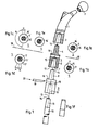
- an attachable joint ball 2 is provided for a head part 1 of a femoral prosthesis.
- the head part 1 has a conical bore 3, in which che a pin 4 of an intermediate part 5 with circular cylindrical body 6 and a conical bore 7 can be used.
- a pin 8 of a further intermediate part 9 fits into the conical bore 7, which is constructed essentially like the intermediate part 5, but has a different length.
- Several such intermediate parts 5, 9 can be joined together to form a shaft in accordance with the resection prosthesis shown in FIG. 1.
- a conical pin 11 of an end piece 12 can be inserted in the lower end of the shaft - namely in a corresponding conical bore 10 of the last intermediate part 9 - a conical pin 11 of an end piece 12 can be inserted.
- the end piece 12 has a conical pin and a cylindrical shaft with a diameter which is smaller than that of the intermediate part and which is intended to be cemented into the medullary cavity.
- the longitudinal axis 13 of the resection prosthesis shown is slightly curved, similar to the natural course of the femur. This curvature is preferably concentrated on the region of the intermediate parts 5, 9, while the head part 1 and the end piece 12 run essentially straight in the shaft region. The slight curvature also results in a certain elasticity, which corresponds better to the physiological one. The introduction of force into the femur is also improved.
- the plane of curvature of the longitudinal axis 13 is located in the plane of the drawing.
- the plane of curvature can also be arranged locally differently - for example, in the case of higher intermediate pieces in a plane that corresponds to the drawing plane.
- the plane of curvature can also be inclined more or less to the plane of the drawing or have a different direction at different height sections.
- Figure 1 the detailed representation according to Figure la shows a top view of the intermediate part 5, namely on the end of the pin 4, which is provided with the spring 14.
- Figure lb is a plan view of the other side of the intermediate part 5 with the surface 17 of the conical bore 7 and the groove 15. If the drawing is folded about the axis 18, it can be seen that a pin 14 according to Figure la fits into a groove 15 according to Figure 1b. It can also be seen that the pin 14 fits into the groove even when the intermediate part 5 in Figure la is rotated by 180 ° about its longitudinal axis.
- the curved intermediate parts 5, 9 are not only suitable for the construction of a left-sided femoral prosthesis, but can also be used in a corresponding manner for the construction of a right-sided prosthesis.
- the prerequisite here is that the plane of curvature of a right-sided prosthesis is pivoted by 180 ° with respect to the plane of curvature for a left-sided prosthesis about the central axis of the body.
- FIGS. 1c and 1d (based on FIGS. 1 a and 1 b) are suitable for this.
- the reference numerals are provided with an apostrophe compared to Figures la and lb. From Figure lc it can be seen that the spring 14 'is bent at the obtuse angle "beta”. The difference angle between 180 ° and "beta” is designated "alpha”. Double that This angle, the groove 15 is widened on one side in FIG. 1d.
- the prosthesis parts are provided with a longitudinal channel for a tie rod extending from the head part 1 to the end piece 12.
- a tie rod extending from the head part 1 to the end piece 12.
- This can be a thin, continuous screw or, preferably, a flexible threaded rod, which the holds individual prosthesis parts together. If a threaded rod is used, it can be shortened to the required length using a cutting tool, such as pliers.
- a tie rod is in itself dispensable, since the cone connections settle under load; however, it is also useful for handling during surgery and for fixing before the actual exposure to the patient's body weight.
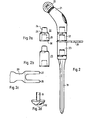
- FIGS. 2 to 2c A further exemplary embodiment of the resection prosthesis according to the invention is shown in FIGS. 2 to 2c.
- a curved shaft part 21 receives the joint head 22 via a cone, with the cone being shown in broken lines in the perspective illustration, correspondingly in the subsequent connections.
- the curved shaft part 21 is followed by two components of different lengths 22 and 23, each of which is shown separately in FIGS. 2a and 2b.
- two components of different lengths 22 and 23 each of which is shown separately in FIGS. 2a and 2b.
- different prosthesis lengths can be realized.
- a cone 24 can be seen, the dimensions of which are adapted to the corresponding, conical recess 25 shown in broken lines, the dimensions of which are used uniformly for the entire system.
- the element 22 has on its side facing the cone 24 two flat chamfers, of which only the chamfer 26 lying at the front in the drawing is visible.
- the two chamfers are parallel to each other and correspond to in their distance is the distance between the inner surfaces of two wedge-shaped prongs 27 and 28 of a fork 29.
- This fork 29 is driven from the side between the elements, as shown in Figure 2.
- the fork-shaped wedge 29 can thus be used easily and is guided without canting by the two chamfers. Penetration of body fluid into the interior of the prosthesis is not possible, so that the prosthesis parts can easily be detached from each other later.
- the wedge-shaped surfaces of part 29 act on the lower boundaries of the chamfer or on the lower edge of the part 1 located above.
- the lower region of the parts having a conical recess contains an additional recess 30 which is designed such that the parts remaining next to the recess overlap the individual parts of the prosthesis on their side having the cone 24 in the region of the chamfers 26 and thus secure them against twisting .
- the end region of the shaft 31 is designed such that it is a receptacle for an artificial one in its lower region already shaped in such a way that the corresponding rolling surfaces are provided on this part.
- Such a design of a total prosthesis results in a high degree of stability and allows an expanded area of application for the prosthesis according to the invention.
- a corresponding element is shown in the drawing in FIG. 2d and forms an alternative embodiment of the shaft end 31 (here designated 31 ′), the rolling surfaces 32 of an artificial knee joint being firmly connected to the shaft end 31 ′ in this embodiment.
- the embodiment of the invention is not limited to the example given above. Rather, a large number of variants are conceivable which make use of the solution shown, even in the case of fundamentally different types.
Abstract
Description
Die Erfindung betrifft einen Bausatz der im Oberbegriff des Anspruchs 1 angegebenen Art.The invention relates to a kit of the type specified in the preamble of claim 1.
Ein solcher Bausatz ist bekannt aus der DE-OS 32 05 577. Die dort beschriebenen Teilstücke, die zu einer Femurprothese gewünschter Länge zusammensteckbar sind, ergeben zusammengesetzt einen relativ starren, gerade verlaufenden Femurersatz. Nachteilig ist dabei, daß eine Demontage, welche im Falle einer Reoperation notwendig werden kann, nur unter Schwierigkeiten möglich ist.Such a kit is known from DE-OS 32 05 577. The sections described there, which form a Femurpro These desired length are pluggable, put together result in a relatively rigid, straight femoral replacement. The disadvantage here is that disassembly, which may be necessary in the event of a reoperation, is only possible with difficulty.
Der mit der bekannten Prothese verbundene Nachteil, daß sich die einzelnen Teile nachträglich nur schlecht voneinander lösen lassen, führt gerade bei Reoperationen und einer im Zusammenhang damit notwendig werdenden Veränderung der Prothese zu Schwierigkeiten. Dabei ist es nämlich wünschenswert, daß die Prothesenteile durch eine einfache Handhabung wieder voneinander getrennt werden können, um gegebenenfalls durch Einsetzen anderer Teile eine veränderte Zusammenstellung zu ermöglichen.The disadvantage associated with the known prosthesis that the individual parts can subsequently only be separated from each other with difficulty, leads to difficulties particularly in the case of reoperations and a change in the prosthesis that is necessary in connection therewith. It is desirable that the prosthesis parts can be separated from each other again by simple handling, in order to enable a different combination if necessary by inserting other parts.
Der in Anspruch 1 angegebenen Erfindung liegt demgemäß die Aufgabe zugrunde, einen Prothesenbausatz der eingangs genannten Gattung anzugeben, welcher es gestattet, die Prothesenteile ohne besonderen Kraftaufwand unter Benutzung eines einfachen Werkzeugs wieder voneinander zu lösen.The invention specified in claim 1 is accordingly based on the object of specifying a prosthesis kit of the type mentioned at the outset, which allows the prosthesis parts to be detached from one another again using a simple tool without any particular effort.
Besonders vorteilhaft bei der Erfindung ist die Tatsache, daß die Prothese beim Lösen der Teile nicht für Schraubbewegungen oder dergleichen verdreht werden muß, so daß die Demontage einzelner Teile auch bei noch teilweise implantiertem Prothesenschaft erfolgen kann.Particularly advantageous with the invention is the fact that the prosthesis does not have to be rotated for screwing movements or the like when the parts are loosened, so that the disassembly of individual parts can also take place with the prosthesis socket still partially implanted.
Bei bevorzugten Weiterbildungen der Erfindung ist der zum Trennen vorgesehene Keil gabelförmig ausgestaltet, so daß der erforderliche Kraftangriff im Randbereich der Prothesenteile erfolgen kann und keine zum Inneren führenden Öffnungen erforderlich sind, welche durch Eindringen von Körperflüssigkeit das Lösen der Prothesenteile voneinander erschweren könnten. Gleichzeitig ist damit auch die Führung erleichtert und der rückwärtige Bereich des Keils läßt sich breiter ausgestalten, so daß er auch unter erschwerten Bedingungen leicht mit einem entsprechenden Schlagwerkzeug getroffen werden kann.In preferred developments of the invention, the wedge provided for cutting is fork-shaped, so that the required force application can take place in the edge area of the prosthesis parts and no openings leading to the inside are required, which could make detachment of the prosthesis parts from one another difficult by the penetration of body fluid. At the same time, the guidance is also facilitated and the rear area of the wedge can be made wider so that it can be easily hit with an appropriate striking tool even under difficult conditions.
Günstig bei der Erfindung ist weiterhin, daß sich bei gabelförmiger Gestaltung des Keils die Ausnehmungen mit den Flächen, welche durch Wechselwirkung mit dem Keil ein Trennen benachbarter Elemente ermöglichen, derart in die Außenkontur der Prothese einfügen lassen, daß sie kaum störend in Erscheinung treten und vor allem die Funktionsfähigkeit der Prothese nicht beeinträchtigen. Wenn die Ausnehmungen durch Anfasungen gebildet werden, können diese bei einer entsprechend ausgebildeten Form des Nachbarteils derart übergriffen werden, daß gleichzeitig eine Sicherung gegen Verdrehen gegeben ist.A further advantage of the invention is that, in the case of a fork-shaped design of the wedge, the recesses with the surfaces which, by interacting with the wedge, enable adjacent elements to be separated, can be inserted into the outer contour of the prosthesis in such a way that they hardly appear in the way and before everything does not affect the functionality of the prosthesis. If the recesses are formed by chamfering, they can be overlapped with a suitably designed shape of the neighboring part in such a way that at the same time there is protection against twisting.
Einer vorteilhaften Weiterbildung der vorliegenden Erfindung liegt die Aufgabe zugunde, einen Bausatz für eine Resektionsprothese insbesondere als Femurersatz zu schaffen, welcher im zusammengesetzten Zustand eine der Krümmung des natürlichen Oberschenkelknochens angenäherte Gestaltung und damit auch ein entsprechendes physiologisches Verhalten unter statischer und dynamischer Belastung zeigt. Dabei sollen möglichst viele Einzelteile des Bausatzes sowohl für den linken Femur als auch für den rechten geeignet sein, um die Lagerhaltung zu vereinfachen. Diese weitere Aufgabe wird dadurch gelöst, daß die Längsachse des Zwischenteiles ähnlich dem Femur gekrümmt ist und die Ausformungen derart gestaltet sind, daß sie in zwei Stellungen ineinanderpassen, in welchen die aneinanderstoßenden Teile um einen Winkel um ihre Längsachse verdreht sind, der 180° beträgt oder dem natürlichen Winkel nahekommt, der zwischen den lokalen Krümmungsebenen der Längsachsen des Femur gelegen ist.An advantageous further development of the present invention is based on the task of creating a kit for a resection prosthesis, in particular as a femoral replacement, which in the assembled state shows a design approximating the curvature of the natural femur and thus also a corresponding physiological behavior under static and dynamic loads. As many individual parts of the kit as possible should be suitable for both the left femur and the right to simplify storage. This further object is achieved in that the longitudinal axis of the intermediate part is curved similar to the femur and the formations are designed such that they fit into one another in two positions in which the abutting parts are rotated by an angle about their longitudinal axis which is 180 ° or approximates the natural angle that lies between the local planes of curvature of the longitudinal axes of the femur.
Andere vorteilhafte Weiterbildungen der Erfindung sind in den übrigen Unteransprüchen angegeben.Other advantageous developments of the invention are specified in the remaining subclaims.
Anhand von in den Zeichnungen wiedergegebenen Ausführungsbeispielen wird das Prinzip der Erfindung und ihrer Ausführungsformen näher erläutert. Es zeigen:
- Figur 1 ein Ausführungsbeispiel eines ersten Bausatzes einschließlich eines die Gelenkkugel tragenden Kopfteils,
- Figuren la bis lf Einzelheiten des Bausatzes gemäß Figur 1,
- Figur 2 ein weiteres Ausführungsbeispiel eines Bausatzes, entsprechend Figur 1 sowie
- Figuren 2a bis 2d Einzelheiten des Bausatzes gemäß Figur 2.
- FIG. 1 shows an exemplary embodiment of a first kit, including a head part carrying the joint ball,
- Figures la to lf details of the kit according to Figure 1,
- Figure 2 shows another embodiment of a kit, corresponding to Figure 1 and
- Figures 2a to 2d details of the kit according to Figure 2.
In Figur 1 ist für ein Kopfteil 1 einer Femurprothese eine aufsteckbare Gelenkkugel 2 vorgesehen. Am unteren Ende weist das Kopf teil 1 eine konische Bohrung 3 auf, in welche ein Zapfen 4 eines Zwischenteiles 5 mit kreiszylindrischem Rumpf 6 und einer konischen Bohrung 7 einsetzbar ist.In FIG. 1, an attachable joint ball 2 is provided for a head part 1 of a femoral prosthesis. At the lower end, the head part 1 has a
In die konische Bohrung 7 wiederum paßt ein Zapfen 8 eines weiteren Zwischenteiles 9, daß im wesentlichen wie das Zwischenteil 5 aufgebaut ist, jedoch eine abweichende Länge aufweist. Mehrere solcher Zwischenteile 5, 9 können zu einem Schaft entsprechend der in Figur 1 gezeigten Resektionsprothese zusammengefügt werden. In das untere Ende des Schafts - nämlich in eine entsprechende konische Bohrung 10 des letzten Zwischenteiles 9 - ist ein konischer Zapfen 11 eines Endstückes 12 steckbar. Das Endstück 12 weist einen konischen Zapfen und einen zylindrischen Schaft mit gegenüber dem Zwischenteil verringertem Durchmesser auf, der dazu bestimmt ist, in den Markraum einzementiert zu werden.In turn, a pin 8 of a further intermediate part 9 fits into the
Die Längsachse 13 der dargestellten Resektionsprothese ist ähnlich dem natürlichen Verlauf des Femur leicht gekrümmt. Bevorzugt ist diese Krümmung auf den Bereich der Zwischenteile 5, 9 konzentriert, während das Kopfteil 1 und das Endstück 12 im Schaftbereich im wesentlichen gerade verläuft. Durch die leichte Krümmung ergibt sich zusätzlich eine gewisse Elastizität, die der physiologischen besser entspricht. Auch ist die Krafteinleitung in den Femur verbessert.The
Zur vereinfachten Darstellung sei hier angenommen, daß die Krümmungsebene der Längsachse 13 in der Zeichenebene gelegen ist. Bei längeren Prothesen kann die Krümmungsebene durchaus auch lokal unterschiedlich angeordnet sein - beispielsweise bei höher gelegenen Zwischenstücken in einer Ebene, wie sie der Zeichenebene entspricht. Bei anderen Ausführungen kann die Krümmungsebene auch mehr oder weniger zur Zeichenebene geneigt sein bzw. in unterschiedlichen Höhenabschnitten eine unterschiedliche Richtung aufweisen.To simplify the illustration, it is assumed here that the plane of curvature of the
Da sich die geringe Krümmung über die gesamte Prothesenlänge von ca. 3 bis 4 Winkelgraden in ihrer Auswirkung auf die einzelnen Teile an diesen vielfach nur schwer erkennen läßt, muß sichergestellt sein, daß diese Zwischenteile in der Weise korrekt zusammengesetzt werden, daß sich der gewünschte Gesamtkrümmungsverlauf ergibt. Um auch eine Sicherung bezüglich der korrekten Richtung der Schaftkrümmung im Halsbereich zu bewirken, sind aufeinander abgestimmte (ineinander fügbare) Ausformungen als Sicherungen gegen Verdrehen um die Achse 13 vorgesehen, und zwar in Gestalt jeweils einer Feder 14 an den Zapfen 4, 8 und 11 und von Nuten 15 in den Bohrungen 3, 7 und 10. Die Federn und Nuten greifen im zusammengesetzten Zustand der Prothese ineinander.Since the slight curvature over the entire length of the prosthesis of approx. 3 to 4 degrees of angle in its effect on the individual parts can often only be recognized with difficulty, it must be ensured that these intermediate parts are correctly assembled in such a way that the desired overall curvature course results. In order to secure the correct direction of the shaft curvature in the neck area, mutually coordinated (interlocking) formations are provided as security against rotation about the
Um das Zusammensetzen zu erleichtern, weisen diese Ausformungen gegeneinander ein geringes Spiel auf. Statt Federn und Nuten als Ausformungen können auch zwei Nasen mit zugehörigen Ausnehmungen oder dergl. vorgesehen sein. Diese Ausformungen können sowohl am Ende der Zapfen bzw. am Grund der Bohrungen, als auch an den aneinanderstoßenden Flächen 16 bzw. 17 vorgesehen sein.In order to facilitate assembly, these formations have little play against one another. Instead of tongues and grooves as formations, two lugs with associated recesses or the like can also be provided. These formations can be provided both at the end of the pegs or at the bottom of the bores and on the
Zu Figur 1 zeigt die Detaildarstellung gemäß Figur la eine Aufsicht auf das Zwischenteil 5, und zwar auf das Ende des Zapfens 4, der mit der Feder 14 versehen ist. In Figur lb ist eine Aufsicht auf die andere Seite des Zwischenteiles 5 mit der Fläche 17 der konischen Bohrung 7 und der Nut 15 dargestellt. Wenn die Zeichnung um die Achse 18 gefaltet wird, ist ersichtlich, daß ein Zapfen 14 gemäß Figur la in eine Nut 15 gemäß Figur lb paßt. Es ist ebenfalls ersichtlich, daß der Zapfen 14 auch dann in die Nut paßt, wenn das Zwischenteil 5 in Figur la um 180° um seine Längsachse gedreht ist. Hieraus folgt, daß die gekrümmten Zwischenteile 5, 9 nicht nur zum Aufbau einer linksseitigen Femurprothese geeignet sind, sondern in entsprechender Weise auch für den Aufbau einer rechtsseitigen Prothese verwendbar sind. Voraussetzung dabei ist, daß die Krümmungsebene einer rechtsseitigen Prothese um 180° gegenüber der Krümmungsebene für eine linksseitige Prothese um die Körpermittelachse geschwenkt ist.For Figure 1, the detailed representation according to Figure la shows a top view of the
Diese vereinfachende Voraussetzung trifft aber nicht über die ganze Länge eines Oberschenkelknochens zu. Vielmehr gibt es Bereiche im Verlaufe des Femur, wo zwischen der linksseitigen Krümmungsebene und der rechtsseitigen ein Winkel "beta" von weniger als 180* liegt. Hierfür sind die Ausführungsbeispiele geeignet, die in den Figuren lc und ld (in Anlehnung an die Figuren la und lb) dargestellt sind. Die Bezugszeichen sind gegenüber den Figuren la und lb mit einem Apostroph versehen. Aus Figur lc geht hervor, daß die Feder 14' in dem stumpfen Winkel "beta" geknickt verläuft. Der Differenzwinkel zwischen 180° und "beta" ist mit "alpha" bezeichnet. Um das Doppelte dieses Winkels ist in Figur ld die Nut 15 einseitig keilförmig erweitert.However, this simplifying requirement does not apply over the entire length of a femur. Rather, there are areas in the course of the femur where there is an angle "beta" of less than 180 * between the left-hand plane of curvature and the right-hand side. The exemplary embodiments shown in FIGS. 1c and 1d (based on FIGS. 1 a and 1 b) are suitable for this. The reference numerals are provided with an apostrophe compared to Figures la and lb. From Figure lc it can be seen that the spring 14 'is bent at the obtuse angle "beta". The difference angle between 180 ° and "beta" is designated "alpha". Double that This angle, the
Wenn die Zeichnung wiederum um die Linie 18 gefaltet gedacht wird, ist ersichtlich, daß die Feder 14' in die Nut 15' paßt. Weiterhin ist erkennbar, daß nach Drehung des Zwischenteils 5 (ausgehend von Figur lc) um den Winkel "beta" die Stellung nach Figur le erhalten wird und das nunmehr die Feder 14' in ihrer neuen Stellung nach Figur le ebenfalls in die Nut 15' nach Figur ld hineinpaßt.If the drawing is again thought to be folded around the
In Figur 1 ist weiterhin eine Möglichkeit zum Lösen der Konusverbindungen angegeben. Hierzu ist bei dem Zwischenteil 9 durch eine Bohrung 18 dafür gesorgt, daß nach dem Einsetzen des Endstückes 12 zwischen dessen Feder 14 und dem Zwischenteil 9 (genauer gesagt: dem oberen Wandungsteil der Bohrung 18) ein Zwischenraum bleibt. Dieser Zwischenraum ist von außen durch die Bohrung 18 für einen Keil 19 zugänglich, der in Richtung eines Pfeiles 20 eingetrieben werden kann, um den konischen Zapfen 11 wieder aus der Bohrung 10 hinauszudrücken. Der Keil 19 stützt sich dabei auf der Feder 14 ab, so daß beim Auseinandertreiben der Teile 9 und 12 die Konusflächen geschont werden.In Figure 1, a way to loosen the cone connections is also specified. For this purpose, it is ensured in the intermediate part 9 through a
Nicht in der Zeichnung dargestellt ist eine praktische Ergänzungsmöglichkeit, die darin besteht, daß die Prothesenteile mit einem Längskanal für einen vom Kopfteil 1 bis zum Endstück 12 reichenden Zuganker versehen sind. Dabei kann es sich um eine dünne durchgehende Schraube oder bevorzugt um eine biegsame Gewindestange handeln, welche die einzelnen Prothesenteile zusammenhält. Bei Verwendung einer Gewindestange kann diese mit einem Schneidwerkzeug, beispielsweise einer Zange, nach Bedarf auf die erforderliche Länge gekürzt werden. Ein solcher Zuganker ist an sich entbehrlich, da die Konusverbindungen sich bei Belastung setzen; er ist aber gleichfalls für die Handhabung während der Operation und zur Fixierung vor dem Beginn der eigentlichen Belastung durch das Körpergewicht des Patienten nützlich.Not shown in the drawing is a practical addition, which consists in that the prosthesis parts are provided with a longitudinal channel for a tie rod extending from the head part 1 to the
In den Figuren 2 bis 2c ist ein weiteres Ausführungsbeispiel der erfindungsgemäßen Resektionsprothese dargestellt. Ein gekrümmter Schaftteil 21 nimmt über einen Konus den Gelenkkopf 22 auf, wobei in der perspektivischen Darstellung der Konus - entsprechend bei den nachfolgenden Verbindungen - jeweils gestrichelt dargestellt ist.A further exemplary embodiment of the resection prosthesis according to the invention is shown in FIGS. 2 to 2c. A
An den gekrümmten Schaftteil 21 schließen sich zwei Bauteile unterschiedlicher Länge 22 und 23 an, welche in den Figuren 2a und 2b jeweils noch einmal separat dargestellt sind. Durch die Variation der Länge der Bauelemente lassen sich unterschiedliche Prothesenlängen realisieren. Bei dem in Figur 2a wiedergegebenen Element 22 ist ein Konus 24 erkennbar, welcher bezüglich seiner Abmessungen an die entsprechende, gestrichelt dargestellte, konusförmige Ausnehmung 25 angepaßt ist, welche in ihren Abmessungen einheitlich für das gesamte System verwendet wird. Das Element 22 weist an seiner dem Konus 24 zugewandten Seite zwei ebene Anfasungen auf, von denen nur die in der Zeichnung vorn liegende Anfasung 26 sichtbar ist. Die beiden Anfasungen liegen parallel zueinander und entsprechen in ihrem Abstand dem Abstand der Innenflächen von zwei keilförmigen Zinken 27 und 28 einer Gabel 29.The
Diese Gabel 29 wird von der Seite her zwischen die Elemente getrieben, wie es in Figur 2 dargestellt ist. Der gabelförmige Keil 29 läßt sich somit leicht einsetzen und wird durch die beiden Anfasungen verkantungsfrei geführt. Ein Eindringen von Körperflüssigkeit in Innenbereiche der Prothese ist dabei nicht möglich, so daß sich die Prothesenteile später in jedem Falle leicht voneinander lösen lassen. Die keilförmigen Flächen des Teils 29 wirken dabei auf unteren Begrenzungen der Anfasungen bzw. auf die Unterkante des jeweils obengelegenen Teils 1.This
Der untere Bereich der eine konusförmige Aussparung aufweisenden Teile enthält eine zusätzliche Ausnehmung 30, welche so beschaffen ist, daß die neben der Ausnehmung verbleibenden Teile die Einzelteile der Prothese an ihrer den Konus 24 aufweisenden Seite im Bereich der Anfasungen 26 übergreifen und somit gegen ein Verdrehen sichern.The lower region of the parts having a conical recess contains an
Falls eine Schaftkrümmung entsprechend der Ausführung als Links- bzw. Rechtsprothese erwünscht ist, sind die Flächen der Anfasung bzw. der diese übergreifenden Ausnehmungen entsprechend dem in Figuren lc bis le dargestellten Ausführungsbeispiel auszugestalten.If a shaft curvature corresponding to the design as a left-hand or right-hand prosthesis is desired, the surfaces of the chamfer or of the recesses overlapping these are to be designed in accordance with the exemplary embodiment shown in FIGS. 1c to 1e.
Bei einem weiteren - in der Zeichnung nicht dargestellten - Ausführungsbeispiel ist der Endbereich des Schafts 31 derart ausgebildet, daß er in seinem unteren Bereich eine Aufnanme fur ein künstliches er ist bereits selbst in einer Weise geformt, daß an diesem Teil die entsprechenden Abrollflächen vorgesehen sind. Eine derartige Ausführung einer Totalprothese ergibt eine hohe Stabilität und läßt einen erweiterten Anwendungsbereich für die erfindungsgemäße Prothese zu. Ein entsprechendes Element ist in der Zeichnung in Figur 2d dargestellt und bildet eine alternative Ausführung des Schaftendes 31 (hier mit 31' bezeichnet), wobei bei dieser Ausführung mit dem Schaftende 31' die Abrollflächen 32 eines künstlichen Kniegelenks fest verbunden sind.In a further exemplary embodiment — not shown in the drawing — the end region of the
Die Erfindung beschränkt sich in ihrer Ausführung nicht auf das vorstehend angegebene Beispiel. Vielmehr sind eine Vielzahl von Varianten denkbar, welche von der dargestellten Lösung auch bei grundsätzlich anders gearteten Ausführungen Gebrauch machen.The embodiment of the invention is not limited to the example given above. Rather, a large number of variants are conceivable which make use of the solution shown, even in the case of fundamentally different types.
Claims (11)
dadurch gekennzeichnet,
daß sich in aneinandergrenzenden Bereichen benachbarter Teile mindestens eine, in die im übrigen ebenmäßige Außenkontur mindestens eines der Teile eingelassene Ausnehmung (15, 26, 30) befindet, welche in zur Implantation ausgerichteter Position insgesamt einen Keil (16, 28) zum Trennen der beiden Teile aufnimmt, wobei an den beiden Teilen einander gegenüberliegenden jeweils im wesentlichen quer verlaufende Anschlagflächen vorgesehen sind, welche jeweils die mittels des Keils ausgeübte, die beiden Teile trennende Kraft aufnehmen.1. Kit for a resection prosthesis with a head part and an end part, of which one part has a conical pin and the other part has a conical bore, at least one intermediate part adapted to the pin and / or bore being provided between these two parts, and the when assembling adjoining surfaces of different parts can be secured against twisting by adapted shapes,
characterized,
that in adjacent areas of adjacent parts there is at least one recess (15, 26, 30) let into the otherwise even outer contour of at least one of the parts, which in the position aligned for implantation has a total of a wedge (16, 28) for separating the two parts receives, on the two parts opposite each other, essentially transverse transverse stop surfaces are provided, each of which absorbs the force exerted by means of the wedge and separating the two parts.
Priority Applications (1)
| Application Number | Priority Date | Filing Date | Title |
|---|---|---|---|
| AT84730121T ATE29834T1 (en) | 1983-11-08 | 1984-11-08 | KIT FOR A RESECTION PROSTHESIS. |
Applications Claiming Priority (2)
| Application Number | Priority Date | Filing Date | Title |
|---|---|---|---|
| DE3340767 | 1983-11-08 | ||
| DE19833340767 DE3340767A1 (en) | 1983-11-08 | 1983-11-08 | KIT FOR A RESECTION PROSTHESIS |
Publications (2)
| Publication Number | Publication Date |
|---|---|
| EP0145641A1 true EP0145641A1 (en) | 1985-06-19 |
| EP0145641B1 EP0145641B1 (en) | 1987-09-23 |
Family
ID=6214027
Family Applications (1)
| Application Number | Title | Priority Date | Filing Date |
|---|---|---|---|
| EP84730121A Expired EP0145641B1 (en) | 1983-11-08 | 1984-11-08 | Modular resection prosthesis assembly |
Country Status (4)
| Country | Link |
|---|---|
| US (1) | US4676797A (en) |
| EP (1) | EP0145641B1 (en) |
| AT (1) | ATE29834T1 (en) |
| DE (2) | DE3340767A1 (en) |
Cited By (17)
| Publication number | Priority date | Publication date | Assignee | Title |
|---|---|---|---|---|
| EP0201442A2 (en) * | 1985-04-05 | 1986-12-17 | France Implant | Modular prosthetic device |
| FR2585945A1 (en) * | 1985-08-06 | 1987-02-13 | Armor | Method of implanting a resection prosthesis in the diaphysis of a long bone and prosthesis allowing implementation of this method. |
| EP0283706A1 (en) * | 1987-03-09 | 1988-09-28 | Waldemar Link (GmbH & Co.) | Hip prosthesis |
| EP0290735A1 (en) * | 1987-05-15 | 1988-11-17 | GebràDer Sulzer Aktiengesellschaft | Kit for the intraoperative construction of a femoral head prosthesis |
| DE8911046U1 (en) * | 1988-09-14 | 1990-02-08 | Pfizer Hospital Products Group, Inc., New York, N.Y., Us | |
| WO1990002533A2 (en) * | 1988-09-09 | 1990-03-22 | Klaus Draenert | Hip-joint prosthesis and use thereof |
| EP0532617A1 (en) * | 1990-06-06 | 1993-03-24 | Ronald Sekel | Hip prosthesis. |
| FR2697996A1 (en) * | 1992-11-17 | 1994-05-20 | Medinov Sa | Femoral prosthesis assembly - has shank whose end can receive series of necks connected to spherical head in variety of positions |
| EP1106148A1 (en) * | 1999-11-25 | 2001-06-13 | Steinicke Maschinen- und Werkzeugbau AG | Extracting instrument for disconnecting individual parts of an endoprosthesis |
| EP1358860A3 (en) * | 2002-04-30 | 2005-12-21 | DePuy Orthopaedics, Inc. | A modular orthopaedic implant system |
| WO2007028832A2 (en) * | 2005-09-09 | 2007-03-15 | Waldemar Link Gmbh & Co. Kg | Endoprothesis set comprising a distraction instrument |
| FR2913590A1 (en) * | 2007-03-14 | 2008-09-19 | Mouzayek Hicham | Modular recovery femoral rod for hip prosthesis of patient, diaphyseal and metaphyseal elements comprising respective conical surfaces that couple with metaphyseal and epiphyseal elements, where surfaces are same |
| WO2013110259A1 (en) * | 2012-01-26 | 2013-08-01 | Merete Medical Gmbh | Adapter system for an endoprosthesis |
| US9615941B2 (en) | 2007-05-02 | 2017-04-11 | Zimmer, Inc. | Orthopedic tool for altering the connection between orthopedic components |
| EP3328303A4 (en) * | 2015-07-27 | 2019-04-03 | HIP Innovation Technology, LLC | Femoral cup or femoral ball extractor |
| EP3498230A1 (en) * | 2017-12-15 | 2019-06-19 | Waldemar Link GmbH & Co. KG | Modular endoprosthesis shaft system with rotating element |
| EP3730097A1 (en) * | 2019-04-26 | 2020-10-28 | Waldemar Link GmbH & Co. KG | Trial neckpiece for a joint endoprosthesis |
Families Citing this family (112)
| Publication number | Priority date | Publication date | Assignee | Title |
|---|---|---|---|---|
| US4822370A (en) * | 1986-01-14 | 1989-04-18 | Orthoplant Endoprothetik | Hip joint femoral prosthesis |
| DE3600804C1 (en) * | 1986-01-14 | 1987-08-13 | Orthoplant Endoprothetik | Hip joint prosthesis with condyle connector |
| DE8605597U1 (en) * | 1986-03-01 | 1986-04-10 | orthoplant Endoprothetik GmbH, 2800 Bremen | Endoprosthesis to replace rod-shaped bones |
| EP0257359B1 (en) * | 1986-08-15 | 1991-11-27 | Boehringer Mannheim Corporation | Modular hip prosthesis |
| US5314479A (en) * | 1986-08-15 | 1994-05-24 | Depuy Inc. | Modular prosthesis |
| US5080685A (en) * | 1986-08-15 | 1992-01-14 | Boehringer Mannheim Corporation | Modular hip prosthesis |
| US4822366A (en) * | 1986-10-16 | 1989-04-18 | Boehringer Mannheim Corporation | Modular knee prosthesis |
| DE3710233A1 (en) * | 1987-03-27 | 1988-10-27 | Gmt Medizinische Technik Gmbh | SADDLE PROSTHESIS |
| FR2619005B1 (en) * | 1987-08-03 | 1993-09-17 | Omci | HIP PROSTHESIS WITH INTERCHANGEABLE EPIPHYSIS |
| US5194066A (en) * | 1988-01-11 | 1993-03-16 | Boehringer Mannheim Corporation | Modular joint prosthesis |
| US4834081A (en) * | 1988-01-11 | 1989-05-30 | Boehringer Mannheim Corporation | Tool for removing modular joint prosthesis |
| US4865609A (en) * | 1988-03-02 | 1989-09-12 | Bioconcepts, Inc. | Modular joint prosthesis assembly and method of removing |
| US4851007A (en) * | 1988-03-18 | 1989-07-25 | Gray Frank B | Femoral component for a hip prosthesis |
| US5658352A (en) * | 1988-09-09 | 1997-08-19 | Draenert; Klaus | Hip prosthesis and its use |
| US5108452A (en) * | 1989-02-08 | 1992-04-28 | Smith & Nephew Richards Inc. | Modular hip prosthesis |
| US5061271A (en) * | 1989-02-27 | 1991-10-29 | Boehringer Mannheim Corporation | Tool for separating components of a modular joint prosthesis |
| US4921500A (en) * | 1989-02-28 | 1990-05-01 | Osteonics Corp. | Femoral head adaptor for interoperative assembly |
| US5015257A (en) * | 1989-03-20 | 1991-05-14 | Zimmer, Inc. | Prosthetic interpositional device/coupler |
| US4963155A (en) * | 1989-08-30 | 1990-10-16 | Zimmer, Inc. | Attachment mechanism for modular surgical products |
| US5201882A (en) * | 1989-11-03 | 1993-04-13 | Paxson Robert D | Modular hip joint prosthesis with adjustable anteversion |
| US5002581A (en) * | 1989-11-03 | 1991-03-26 | Dow Corning Wright Corporation | Modular hip joint prosthesis with adjustable anteversion |
| US4997444A (en) * | 1989-12-28 | 1991-03-05 | Zimmer, Inc. | Implant having varying modulus of elasticity |
| US5100407A (en) * | 1990-09-04 | 1992-03-31 | Pfizer Hospital Products Group, Inc. | Modular trial hip replacement system |
| DE4028510C2 (en) * | 1990-09-07 | 1994-12-01 | Link Waldemar Gmbh Co | Endoprosthesis |
| US5108449A (en) * | 1990-12-31 | 1992-04-28 | Gray Frank B | Femoral component for a hip prosthesis |
| US5658349A (en) * | 1991-07-29 | 1997-08-19 | Joint Medical Products Corporation | Prosthetic joint system for bone replacement |
| US5156624A (en) * | 1991-09-06 | 1992-10-20 | Zimmer, Inc. | Head adaptor for hip prosthesis |
| US5342366A (en) * | 1992-02-19 | 1994-08-30 | Biomet, Inc. | Surgical instruments for hip revision |
| EP0558203A1 (en) * | 1992-02-20 | 1993-09-01 | Wright Medical Technology, Inc. | Modular trial instrument with interlock mechanism |
| CH685533A5 (en) * | 1992-10-13 | 1995-08-15 | Philipp Rolf Kropf Albert Geis | Modular hip prosthesis stem. |
| US5961555A (en) | 1998-03-17 | 1999-10-05 | Huebner; Randall J. | Modular shoulder prosthesis |
| ES2069473B1 (en) * | 1993-06-04 | 1996-02-16 | Levante Ind Quirurgicas | PROTESIS OF OSEA SUBSTITUTION OF MODULAR DESIGN. |
| DE4320086C3 (en) * | 1993-06-17 | 2002-05-16 | Peter Brehm | Modular shaft for a revision hip prosthesis system |
| US5405403A (en) * | 1994-03-18 | 1995-04-11 | Mikhail; W. E. Michael | Femoral prosthesis with anti-rotation feature for ball |
| US5489284A (en) * | 1994-07-15 | 1996-02-06 | Smith & Nephew Richards Inc. | Cannulated modular intramedullary nail |
| US5620445A (en) * | 1994-07-15 | 1997-04-15 | Brosnahan; Robert | Modular intramedullary nail |
| US5569263A (en) * | 1995-01-12 | 1996-10-29 | Orthopaedic Innovations, Inc. | Adjustable provisional articulating device |
| US5645607A (en) * | 1995-03-02 | 1997-07-08 | Zimmer, Inc. | Hip stem provisional having adjustable neck offsets |
| DE19680996D2 (en) * | 1995-11-20 | 1999-01-28 | Artos Med Produkte | Modular endoprosthesis |
| GB9707371D0 (en) * | 1997-04-11 | 1997-05-28 | Minnesota Mining & Mfg | A modular humeral prosthesis |
| US6494913B1 (en) | 1998-03-17 | 2002-12-17 | Acumed, Inc. | Shoulder prosthesis |
| US7189261B2 (en) | 1998-04-03 | 2007-03-13 | Smith & Nephew, Inc. | Modular humeral prosthesis and method |
| US6149687A (en) * | 1998-07-10 | 2000-11-21 | Sulzer Orthopedics Inc. | Offset trial stem |
| US6702854B1 (en) | 1999-06-01 | 2004-03-09 | Apex Surgical, Llc | Implantable joint prosthesis |
| US6238435B1 (en) | 2000-03-10 | 2001-05-29 | Bristol-Myers Squibb Co | Assembly tool for prosthetic implant |
| US6319286B1 (en) | 2000-03-13 | 2001-11-20 | Exactech, Inc | Modular hip prosthesis |
| US8114163B2 (en) | 2000-04-10 | 2012-02-14 | Biomet Manufacturing Corp. | Method and apparatus for adjusting height and angle for a radial head |
| US8535382B2 (en) | 2000-04-10 | 2013-09-17 | Biomet Manufacturing, Llc | Modular radial head prostheses |
| US8920509B2 (en) | 2000-04-10 | 2014-12-30 | Biomet Manufacturing, Llc | Modular radial head prosthesis |
| AU2001257443A1 (en) | 2000-05-03 | 2001-11-12 | Smith And Nephew, Inc. | Multi modular trialing system and instrumentation |
| US6613092B1 (en) * | 2000-07-19 | 2003-09-02 | Centerpulse Orthopedics Inc. | Stem taper adapter |
| US6589281B2 (en) * | 2001-01-16 | 2003-07-08 | Edward R. Hyde, Jr. | Transosseous core approach and instrumentation for joint replacement and repair |
| US20020120340A1 (en) * | 2001-02-23 | 2002-08-29 | Metzger Robert G. | Knee joint prosthesis |
| US7497874B1 (en) * | 2001-02-23 | 2009-03-03 | Biomet Manufacturing Corp. | Knee joint prosthesis |
| US6953479B2 (en) | 2001-07-16 | 2005-10-11 | Smith & Nephew, Inc. | Orthopedic implant extension |
| US7097663B1 (en) | 2001-12-17 | 2006-08-29 | Smith & Nephew, Inc. | Modular prosthesis system with novel locking mechanism |
| DE10200125A1 (en) * | 2002-01-04 | 2003-07-24 | Intraplant Ag Cham | Modular hip joint endoprosthesis has conical connection between spherical head and trochant segment and between trochant segment and shaft |
| AUPS038802A0 (en) * | 2002-02-08 | 2002-02-28 | Portland Orthopaedics Pty Limited | Modulear prosthesis with adjustable taper |
| US6902583B2 (en) | 2002-04-25 | 2005-06-07 | Medicinelodge, Inc. | Tripartite attachment mechanism and method for a modular prosthesis |
| US7182786B2 (en) | 2002-04-25 | 2007-02-27 | Zimmer Technology, Inc. | Modular bone implant, tool, and method |
| US6875239B2 (en) * | 2002-04-25 | 2005-04-05 | Medicinelodge, Inc. | Modular prosthesis for replacing bone and method |
| US20030204268A1 (en) * | 2002-04-25 | 2003-10-30 | Medicinelodge, Inc. | Binary attachment mechanism and method for a modular prosthesis |
| US6887276B2 (en) * | 2002-12-13 | 2005-05-03 | Medicine Lodge, Inc | Modular implant for joint reconstruction and method of use |
| US6866683B2 (en) | 2002-12-13 | 2005-03-15 | Medicine Lodge, Inc. | Modular implant for joint reconstruction and method of use |
| US7854737B2 (en) * | 2002-12-20 | 2010-12-21 | Depuy Products, Inc. | Instrument and associated method of trailing for modular hip stems |
| US7235106B2 (en) * | 2002-12-20 | 2007-06-26 | Depuy Products, Inc. | Modular hip stems and associated method of trialing |
| US7125423B2 (en) * | 2003-03-31 | 2006-10-24 | Depuy Products, Inc. | Intercalary prosthesis, kit and method |
| US7198642B2 (en) * | 2003-03-31 | 2007-04-03 | Depuy Products, Inc. | Orthopaedic spacer |
| US7141067B2 (en) * | 2003-03-31 | 2006-11-28 | Depuy Products, Inc. | Intercalary implant |
| US7153326B1 (en) | 2003-06-19 | 2006-12-26 | Biomet Manufacturing Corp. | Method and apparatus for use of an offset stem connection |
| US7435263B2 (en) * | 2003-09-30 | 2008-10-14 | Depuy Products, Inc. | Modular long bone prosthesis for partial or total bone replacement |
| DE112004001893B4 (en) * | 2003-10-09 | 2018-06-21 | Omni Life Science, Inc. | Conical joint prosthesis |
| FR2861577B1 (en) * | 2003-11-05 | 2006-02-10 | Ceravic | IMPLANTABLE ORTHESIS AND SURGICAL KIT FOR ARTHRODESIS OF THE KNEE |
| CA2515364A1 (en) * | 2003-12-12 | 2005-07-07 | Mariasal Investment N.V. | Movable neck and stem for hip prosthesis, made in such a way as to facilitate their disengagement |
| US7135044B2 (en) * | 2004-03-09 | 2006-11-14 | Howmedics Osteonics Corp. | Modular prosthesis kits |
| US8273093B2 (en) | 2004-06-29 | 2012-09-25 | Depuy Products, Inc. | Instrumentation for recording and replicating orthopaedic implant orientation |
| US7867282B2 (en) * | 2004-12-17 | 2011-01-11 | Depuy Products, Inc. | Modular implant system and method with diaphyseal implant and adapter |
| AU2005317184B2 (en) * | 2004-12-17 | 2011-10-13 | Depuy Products, Inc. | Modular implant system and method with diaphyseal implant and adapter |
| US7507256B2 (en) * | 2004-12-17 | 2009-03-24 | Depuy Products, Inc. | Modular implant system and method with diaphyseal implant |
| US8460390B2 (en) * | 2004-12-29 | 2013-06-11 | Depuy Products, Inc. | System and method for replicating orthopaedic implant orientation |
| US8444698B2 (en) | 2004-12-29 | 2013-05-21 | Depuy Products, Inc. | Joint prosthesis with infinitely positionable head |
| US7998218B1 (en) * | 2005-02-02 | 2011-08-16 | Biomet Manufacturing Corp. | Modular orthopedic implant |
| US7998217B1 (en) | 2005-02-02 | 2011-08-16 | Biomet Manufacturing Corp. | Modular offset stem implants |
| JP4852596B2 (en) * | 2005-03-14 | 2012-01-11 | インボーン テクノロジーズ, インコーポレイテッド | Ankle replacement prosthesis |
| US8679185B2 (en) | 2005-09-30 | 2014-03-25 | DePuy Synthes Products, LLC | Joint prosthesis with positionable head |
| DE202005020876U1 (en) * | 2005-11-16 | 2006-10-05 | Plus Orthopedics Ag | Endoprosthesis comprises a shaft, which extends along a primary axis, a distal end piece and a proximal end piece |
| US7842093B2 (en) * | 2006-07-18 | 2010-11-30 | Biomet Manufacturing Corp. | Method and apparatus for a knee implant |
| US7537618B2 (en) * | 2006-11-13 | 2009-05-26 | Howmedica Osteonics Corp. | Modular humeral head |
| AU2006351469B2 (en) | 2006-12-07 | 2012-10-18 | Ihip Surgical, Llc | Method and apparatus for total hip replacement |
| US8579985B2 (en) | 2006-12-07 | 2013-11-12 | Ihip Surgical, Llc | Method and apparatus for hip replacement |
| US8974540B2 (en) | 2006-12-07 | 2015-03-10 | Ihip Surgical, Llc | Method and apparatus for attachment in a modular hip replacement or fracture fixation device |
| US8328873B2 (en) | 2007-01-10 | 2012-12-11 | Biomet Manufacturing Corp. | Knee joint prosthesis system and method for implantation |
| US8187280B2 (en) | 2007-10-10 | 2012-05-29 | Biomet Manufacturing Corp. | Knee joint prosthesis system and method for implantation |
| US8562616B2 (en) | 2007-10-10 | 2013-10-22 | Biomet Manufacturing, Llc | Knee joint prosthesis system and method for implantation |
| JP5448842B2 (en) | 2007-01-10 | 2014-03-19 | バイオメト マニファクチャリング コーポレイション | Knee joint prosthesis system and implantation method |
| US8163028B2 (en) | 2007-01-10 | 2012-04-24 | Biomet Manufacturing Corp. | Knee joint prosthesis system and method for implantation |
| CH701386B1 (en) * | 2007-03-20 | 2011-01-14 | Mariasal Invest Nv | Mobile femoral neck stem for hip replacement. |
| US7981161B2 (en) * | 2007-08-17 | 2011-07-19 | Howmedica Osteonics Corp. | Disposable neck trial adapter |
| GB0716403D0 (en) * | 2007-08-22 | 2007-10-03 | Benoist Girard Sas | Trial prosthetic neck component |
| US8002838B2 (en) * | 2008-06-11 | 2011-08-23 | Depuy Products, Inc. | Joint prosthesis with positionable head |
| DE102008045291B4 (en) | 2008-09-02 | 2013-05-02 | Merete Medical Gmbh | Knee arthrodesis implant |
| DE102008049123B4 (en) | 2008-09-26 | 2013-06-06 | Merete Medical Gmbh | Modular joint prosthesis |
| US8758446B2 (en) * | 2009-03-23 | 2014-06-24 | Biomet Manufacturing, Llc | Method and apparatus for protecting modular implant connection |
| US20110112649A1 (en) * | 2009-11-09 | 2011-05-12 | Biomet Manufacturing Corp. | Radial and ulnar replacement |
| EP2685939B1 (en) | 2011-03-16 | 2016-11-02 | Smith&Nephew, Inc. | Anatomic guide |
| EP2689749B1 (en) * | 2012-07-26 | 2016-06-08 | WALDEMAR LINK GmbH & Co. KG | Clip-on module for a long shaft prosthetic |
| US9949839B2 (en) | 2013-03-13 | 2018-04-24 | Wright Medical Technology, Inc. | Revision implant augments, systems, and methods |
| US9101479B2 (en) * | 2013-03-15 | 2015-08-11 | Depuy (Ireland) | Prosthetic components and methods for joint line access |
| US10136998B2 (en) | 2016-08-30 | 2018-11-27 | Wright Medical Technology, Inc. | Revision total ankle implants |
| US10751186B2 (en) * | 2017-09-12 | 2020-08-25 | Zimmer, Inc. | Methods for attaching acetabular augments together or to acetabular shells |
| CN109875730A (en) * | 2019-03-05 | 2019-06-14 | 福建医科大学附属第一医院 | A kind of structure and its application method of femoral prosthesis |
| US20220316504A1 (en) * | 2021-04-01 | 2022-10-06 | Wright Medical Technology, Inc. | Coupling systems and methods |
Citations (2)
| Publication number | Priority date | Publication date | Assignee | Title |
|---|---|---|---|---|
| EP0011665A1 (en) * | 1978-11-23 | 1980-06-11 | Osteo Ag | Set for endoprosthesis and process for adjusting the length of the neck of this endoprosthesis |
| DE3205577A1 (en) * | 1981-02-23 | 1982-10-28 | Howmedica International, Inc. Zweigniederlassung Kiel, 2300 Kiel | Bone prosthesis |
Family Cites Families (11)
| Publication number | Priority date | Publication date | Assignee | Title |
|---|---|---|---|---|
| DE8108959U1 (en) * | 1981-08-13 | Central'nyj naučno-issledovatel'skij institut travmatologii i ortopedii imeni N.N. Priorova, Moskva | Facility for restoring limb function | |
| US1393930A (en) * | 1919-08-30 | 1921-10-18 | Elijah K Wolfe | Grate-shaker bar |
| US2869907A (en) * | 1956-07-20 | 1959-01-20 | Deliso John | Socket and rod coupling |
| US3485520A (en) * | 1968-05-01 | 1969-12-23 | Rayburn G Alexander | Self-locking connection between rigid members and method of making same |
| DE2451275C2 (en) * | 1974-10-29 | 1982-08-26 | Feldmühle AG, 4000 Düsseldorf | Head part of a hip joint prosthesis to be implanted |
| DE2454181C3 (en) * | 1974-11-15 | 1980-02-21 | Rosenthal Technik Ag, 8672 Selb | Ceramic implant |
| SU797680A1 (en) * | 1979-03-19 | 1981-01-23 | Центральный Ордена Трудовогокрасного Знамени Научно-Иссле-Довательский Институт Травматологиии Ортопедии Им.H.H.Приорова | Artificial hip joint |
| FR2475891A1 (en) * | 1979-12-06 | 1981-08-21 | Peze William | Artificial hip joint prosthesis - has external wing on curved portion fixed in recess in large trochanter |
| US4368789A (en) * | 1980-11-03 | 1983-01-18 | Orr . . . Screw Machine Products, Inc. | Drilling apparatus |
| GB2094629B (en) * | 1981-03-14 | 1984-08-01 | Tsnii | Artifical hip knee and femur |
| DE3138848A1 (en) * | 1981-09-30 | 1983-04-21 | GMT GESELLSCHAFT FüR MEDIZINISCHE TECHNIK MBH | ENDOPROTHESIS TO REPLACE ROD-SHAPED BONES |
-
1983
- 1983-11-08 DE DE19833340767 patent/DE3340767A1/en not_active Withdrawn
-
1984
- 1984-11-07 US US06/721,674 patent/US4676797A/en not_active Expired - Lifetime
- 1984-11-08 AT AT84730121T patent/ATE29834T1/en not_active IP Right Cessation
- 1984-11-08 EP EP84730121A patent/EP0145641B1/en not_active Expired
- 1984-11-08 DE DE8484730121T patent/DE3466350D1/en not_active Expired
Patent Citations (2)
| Publication number | Priority date | Publication date | Assignee | Title |
|---|---|---|---|---|
| EP0011665A1 (en) * | 1978-11-23 | 1980-06-11 | Osteo Ag | Set for endoprosthesis and process for adjusting the length of the neck of this endoprosthesis |
| DE3205577A1 (en) * | 1981-02-23 | 1982-10-28 | Howmedica International, Inc. Zweigniederlassung Kiel, 2300 Kiel | Bone prosthesis |
Cited By (28)
| Publication number | Priority date | Publication date | Assignee | Title |
|---|---|---|---|---|
| EP0201442A3 (en) * | 1985-04-05 | 1987-01-07 | France Implant | Modular prosthetic device |
| EP0201442A2 (en) * | 1985-04-05 | 1986-12-17 | France Implant | Modular prosthetic device |
| FR2585945A1 (en) * | 1985-08-06 | 1987-02-13 | Armor | Method of implanting a resection prosthesis in the diaphysis of a long bone and prosthesis allowing implementation of this method. |
| EP0283706A1 (en) * | 1987-03-09 | 1988-09-28 | Waldemar Link (GmbH & Co.) | Hip prosthesis |
| EP0290735A1 (en) * | 1987-05-15 | 1988-11-17 | GebràDer Sulzer Aktiengesellschaft | Kit for the intraoperative construction of a femoral head prosthesis |
| CH671689A5 (en) * | 1987-05-15 | 1989-09-29 | Sulzer Ag | |
| WO1990002533A3 (en) * | 1988-09-09 | 1990-06-14 | Klaus Draenert | Hip-joint prosthesis and use thereof |
| EP0617933A1 (en) * | 1988-09-09 | 1994-10-05 | DRAENERT, Klaus, Dr.med. | Hip-joint prosthesis and use thereof |
| WO1990002533A2 (en) * | 1988-09-09 | 1990-03-22 | Klaus Draenert | Hip-joint prosthesis and use thereof |
| EP0359485A1 (en) * | 1988-09-14 | 1990-03-21 | Pfizer Hospital Products Group, Inc. | Modular prosthesis |
| US5108437A (en) * | 1988-09-14 | 1992-04-28 | Pfizer Hospital Products Group, Inc. | Modular prosthesis |
| DE8911046U1 (en) * | 1988-09-14 | 1990-02-08 | Pfizer Hospital Products Group, Inc., New York, N.Y., Us | |
| EP0532617A1 (en) * | 1990-06-06 | 1993-03-24 | Ronald Sekel | Hip prosthesis. |
| EP0532617A4 (en) * | 1990-06-06 | 1993-04-07 | Ronald Sekel | Hip prosthesis |
| FR2697996A1 (en) * | 1992-11-17 | 1994-05-20 | Medinov Sa | Femoral prosthesis assembly - has shank whose end can receive series of necks connected to spherical head in variety of positions |
| EP1106148A1 (en) * | 1999-11-25 | 2001-06-13 | Steinicke Maschinen- und Werkzeugbau AG | Extracting instrument for disconnecting individual parts of an endoprosthesis |
| EP1358860A3 (en) * | 2002-04-30 | 2005-12-21 | DePuy Orthopaedics, Inc. | A modular orthopaedic implant system |
| WO2007028832A3 (en) * | 2005-09-09 | 2007-07-19 | Link Waldemar Gmbh Co | Endoprothesis set comprising a distraction instrument |
| WO2007028832A2 (en) * | 2005-09-09 | 2007-03-15 | Waldemar Link Gmbh & Co. Kg | Endoprothesis set comprising a distraction instrument |
| FR2913590A1 (en) * | 2007-03-14 | 2008-09-19 | Mouzayek Hicham | Modular recovery femoral rod for hip prosthesis of patient, diaphyseal and metaphyseal elements comprising respective conical surfaces that couple with metaphyseal and epiphyseal elements, where surfaces are same |
| US9615941B2 (en) | 2007-05-02 | 2017-04-11 | Zimmer, Inc. | Orthopedic tool for altering the connection between orthopedic components |
| WO2013110259A1 (en) * | 2012-01-26 | 2013-08-01 | Merete Medical Gmbh | Adapter system for an endoprosthesis |
| EP3328303A4 (en) * | 2015-07-27 | 2019-04-03 | HIP Innovation Technology, LLC | Femoral cup or femoral ball extractor |
| EP3498230A1 (en) * | 2017-12-15 | 2019-06-19 | Waldemar Link GmbH & Co. KG | Modular endoprosthesis shaft system with rotating element |
| WO2019115515A1 (en) * | 2017-12-15 | 2019-06-20 | Waldemar Link Gmbh & Co. Kg | Modular endoprosthesis shaft system with rotation element |
| US11654029B2 (en) | 2017-12-15 | 2023-05-23 | Waldemar Link Gmbh & Co. Kg | Modular endoprosthesis shaft system with rotation element |
| EP3730097A1 (en) * | 2019-04-26 | 2020-10-28 | Waldemar Link GmbH & Co. KG | Trial neckpiece for a joint endoprosthesis |
| WO2020216887A1 (en) * | 2019-04-26 | 2020-10-29 | Waldemar Link Gmbh & Co. Kg | Trial neck piece for a joint endoprosthesis |
Also Published As
| Publication number | Publication date |
|---|---|
| DE3340767A1 (en) | 1985-05-15 |
| ATE29834T1 (en) | 1987-10-15 |
| US4676797A (en) | 1987-06-30 |
| DE3466350D1 (en) | 1987-10-29 |
| EP0145641B1 (en) | 1987-09-23 |
Similar Documents
| Publication | Publication Date | Title |
|---|---|---|
| EP0145641B1 (en) | Modular resection prosthesis assembly | |
| DE2611985C3 (en) | Femoral head endoprosthesis | |
| DE60133370T2 (en) | SPINE IMPLANT AND INTRODUCTION DEVICE | |
| EP1729673B1 (en) | Cervical intervertebral prosthesis | |
| DE60309520T2 (en) | Two-part prosthesis element and method for assembling such a prosthesis element | |
| EP2114274B1 (en) | Plate-implant, in particular for use on a spinal column | |
| DE2447772A1 (en) | JOINT ENDOPROTHESIS | |
| WO1996015739A1 (en) | Modular joint prosthesis | |
| EP0402810B1 (en) | Implantation set | |
| DE3205577C2 (en) | Endoprosthesis for femoral or tibial articular bone parts and adjacent femoral or tibial bone sections | |
| EP1639968A1 (en) | Implant with a part to be inserted and anchored in a bone cavity | |
| DE10247762A1 (en) | Intervertebral prosthesis | |
| EP0121491A1 (en) | Implant | |
| DE2941266A1 (en) | Hip joint endoprosthesis | |
| DE2728690C3 (en) | Joint implant | |
| DE3336005C2 (en) | ||
| EP0721767A2 (en) | Endoprosthesis | |
| EP0669116A1 (en) | Femoral part for a hip joint endoprosthesis | |
| EP1468656A1 (en) | Osteosynthesis device | |
| DE3624525C2 (en) | ||
| WO2007124607A1 (en) | Shaft for a joint prosthesis | |
| DE8306663U1 (en) | Implant | |
| DE3347055A1 (en) | Prosthetic intermediate piece for a bone | |
| DE3935488C2 (en) | ||
| EP1350486A1 (en) | Endoprosthesis |
Legal Events
| Date | Code | Title | Description |
|---|---|---|---|
| PUAI | Public reference made under article 153(3) epc to a published international application that has entered the european phase |
Free format text: ORIGINAL CODE: 0009012 |
|
| AK | Designated contracting states |
Designated state(s): AT BE CH DE FR GB IT LI |
|
| 17P | Request for examination filed |
Effective date: 19851109 |
|
| 17Q | First examination report despatched |
Effective date: 19861212 |
|
| ITF | It: translation for a ep patent filed |
Owner name: BARZANO' E ZANARDO MILANO S.P.A. |
|
| GRAA | (expected) grant |
Free format text: ORIGINAL CODE: 0009210 |
|
| AK | Designated contracting states |
Kind code of ref document: B1 Designated state(s): AT BE CH DE FR GB IT LI |
|
| REF | Corresponds to: |
Ref document number: 29834 Country of ref document: AT Date of ref document: 19871015 Kind code of ref document: T |
|
| ET | Fr: translation filed | ||
| REF | Corresponds to: |
Ref document number: 3466350 Country of ref document: DE Date of ref document: 19871029 |
|
| GBT | Gb: translation of ep patent filed (gb section 77(6)(a)/1977) | ||
| PLBE | No opposition filed within time limit |
Free format text: ORIGINAL CODE: 0009261 |
|
| STAA | Information on the status of an ep patent application or granted ep patent |
Free format text: STATUS: NO OPPOSITION FILED WITHIN TIME LIMIT |
|
| 26N | No opposition filed | ||
| PGFP | Annual fee paid to national office [announced via postgrant information from national office to epo] |
Ref country code: AT Payment date: 19911125 Year of fee payment: 8 |
|
| ITTA | It: last paid annual fee | ||
| PGFP | Annual fee paid to national office [announced via postgrant information from national office to epo] |
Ref country code: CH Payment date: 19911218 Year of fee payment: 8 |
|
| PG25 | Lapsed in a contracting state [announced via postgrant information from national office to epo] |
Ref country code: AT Effective date: 19921108 |
|
| PG25 | Lapsed in a contracting state [announced via postgrant information from national office to epo] |
Ref country code: LI Effective date: 19921130 Ref country code: CH Effective date: 19921130 |
|
| REG | Reference to a national code |
Ref country code: GB Ref legal event code: 732E |
|
| ITPR | It: changes in ownership of a european patent |
Owner name: CAMBIO RAGIONE SOCIALE;JOHNSON & JOHNSON PROFESSIO |
|
| REG | Reference to a national code |
Ref country code: FR Ref legal event code: TP |
|
| REG | Reference to a national code |
Ref country code: CH Ref legal event code: AUV Free format text: DIE OBENGENANNTEN PATENTE SIND, MANGELS BEZAHLUNG DER 9. JAHRESGEBUEHR GELOESCHT WORDEN. Ref country code: CH Ref legal event code: PL |
|
| PGFP | Annual fee paid to national office [announced via postgrant information from national office to epo] |
Ref country code: FR Payment date: 19940418 Year of fee payment: 10 |
|
| PGFP | Annual fee paid to national office [announced via postgrant information from national office to epo] |
Ref country code: GB Payment date: 19940421 Year of fee payment: 10 |
|
| PGFP | Annual fee paid to national office [announced via postgrant information from national office to epo] |
Ref country code: BE Payment date: 19940506 Year of fee payment: 10 |
|
| PG25 | Lapsed in a contracting state [announced via postgrant information from national office to epo] |
Ref country code: GB Effective date: 19941108 |
|
| PG25 | Lapsed in a contracting state [announced via postgrant information from national office to epo] |
Ref country code: BE Effective date: 19941130 |
|
| BERE | Be: lapsed |
Owner name: ARTOS MEDIZINISCHE PRODUKTE G.M.B.H. Effective date: 19941130 |
|
| GBPC | Gb: european patent ceased through non-payment of renewal fee |
Effective date: 19941108 |
|
| PG25 | Lapsed in a contracting state [announced via postgrant information from national office to epo] |
Ref country code: FR Effective date: 19950731 |
|
| REG | Reference to a national code |
Ref country code: FR Ref legal event code: ST |
|
| PGFP | Annual fee paid to national office [announced via postgrant information from national office to epo] |
Ref country code: DE Payment date: 20031120 Year of fee payment: 20 |