EP0145461A2 - Rescue device - Google Patents
Rescue device Download PDFInfo
- Publication number
- EP0145461A2 EP0145461A2 EP84308500A EP84308500A EP0145461A2 EP 0145461 A2 EP0145461 A2 EP 0145461A2 EP 84308500 A EP84308500 A EP 84308500A EP 84308500 A EP84308500 A EP 84308500A EP 0145461 A2 EP0145461 A2 EP 0145461A2
- Authority
- EP
- European Patent Office
- Prior art keywords
- strap
- rigid member
- slider
- rescue device
- person
- Prior art date
- Legal status (The legal status is an assumption and is not a legal conclusion. Google has not performed a legal analysis and makes no representation as to the accuracy of the status listed.)
- Withdrawn
Links
Images

Classifications
-
- B—PERFORMING OPERATIONS; TRANSPORTING
- B63—SHIPS OR OTHER WATERBORNE VESSELS; RELATED EQUIPMENT
- B63C—LAUNCHING, HAULING-OUT, OR DRY-DOCKING OF VESSELS; LIFE-SAVING IN WATER; EQUIPMENT FOR DWELLING OR WORKING UNDER WATER; MEANS FOR SALVAGING OR SEARCHING FOR UNDERWATER OBJECTS
- B63C9/00—Life-saving in water
- B63C9/26—Cast or life lines; Attachments thereto; Containers therefor; Rescue nets or the like
Definitions
- the present invention relates to a rescue device to rescue a person from water. It very often happens in sailing and other boating activities that a person falls overboard and, if the sea or other water is rough, it is quite difficult to rescue the person quickly. Most sailors in fact wear buoyancy aids but it is nonetheless very difficult to bring a boat in rough water closely adjacent to a person who has fallen in the water and thereafter to pull the person into the boat.
- a rescue device comprising an elongate rigid member, a flexible strap having first and second ends, the first end of the strap being secured to one end of the rigid member and a slider slidable along at least a portion of the member from a position spaced from the one end thereof towards said one end, the second end of the strap being attached to said slider, whereby, with the slider located at said position, the strap and said portion of the rigid member form a loop which can be placed over the body of a person to be rescued from water and the other end of the member can then be pulled, thereby causing the slider to move towards the said one end of the rigid member, to tighten the strap around the person.
- the portion of the rigid member is made arcuate thereby to give a preformed portion of the loop.
- the arcuate portion is part-circular and preferably semi-circular, the strap then forming the other part of a circular loop.
- Preferably means are provided releasably to retain the slider at said position to prevent the slider moving along the portion of the rigid member during the act of placing it over the head of the person in the water.
- This may take many forms and could be a simple catch or it could be a thin line extending to the other end of the rigid member which is held by the rescuer during the time while the loop is passed over the person to be rescued's head.
- the strap can take many forms. It could be a simple line or rope and the slider could be a looped portion or eye formed in the end of the rope and passed over the rigid member.
- the strap is in the form of a flat belt and in order to retain the flat belt so that its flat surface is applied against the body of the person to be rescued, the first end of the belt is preferably secured to the one end of the rigid member to hold the plane of the belt at the first end transverse to the plane of the loop.
- the rigid member may have such a cross-section and the slider have such a cooperating shape as to guide the slider in a particular orientation, thereby to hold the plane of the belt at the second end transverse to the plane of the loop, thus effectively maintaining the belt in an arcuate vertical orientation as it is placed over the person's head.
- the strap may in fact be provided with a stiffener to preform it into the shape of the remainder of the loop.
- the rigid member may be solid or is preferably in the form of a tube and a line may be attached to the other end of the rigid member for safety reasons and to assist in pulling the person to be rescued in.
- This line may be passed through the tube and fixed to the first end of the strap.
- a rigid member in the form of an elongate tube 10 having adjacent one end 12 an arcuate portion 14 which is of generally semi-circular shape.
- a line 16 passes from said one end 12 through the tube and out of the other end 18 where it may, for example, be secured to a cleat 17.
- a strap in the form of a belt 20 Fixed to the one end 12 is a strap in the form of a belt 20, one end of which is secured to the line 16 adjacent the end 12, or to some other means adjacent the end 12, preferably to retain the strap in a vertical plane, as seen in Figure 1, adjacent the end 12.
- the other end 24 of the strap 20 is secured to a slider 26.
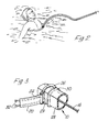
- the tube 10 is provided with a flattened section 28 which can be seen more clearly in Figure 3 and the slider 26 is provided with a straight portion 29 overlying the flattened portion 28 thereby to prevent the slider from rotating about the axis of the tube 10.
- a combined stop and retainer 30 is mounted on the exterior of the tube 10 adjacent a position 15 of the tube at the end of the arcuate portion 14.
- the strap or belt 20 is provided with stiffeners 32 to preform the belt to the upper half of the circle as illustrated in Figure 1.
- a stop 34 At the end 12 of the tube 10, there is a stop 34 to prevent the slider going beyond the end.
- the boat grasps the tube 10 adjacent the end 14, the line 16 having previously been secured e.g. by the cleat 17.
- the loop formed by the strap 20 and the arcuate portion 14 is then placed over the head of the person in the water, the loop being sufficiently large, for example, of the order of 1 metre/In diameter, to pass easily over the head and shoulders of the person to be rescued. If the device is then pushed downwardly so that the portion 14 and strap 20 go below,the arms of the person in the water, it can then be pulled at the end 14 so that the traveller will move along the portion 14 until it arrives at the end 12.
- the stop 34 then prevents the traveller moving there-beyond.
- the loop will then become very much smaller and will have approximately half its original circumference. If one continues to pull then the person will be retained and can be pulled towards the boat and then pulled inboard fairly readily.
- the retaining means 30 can take several forms. For example it could simply be a latch, or a thickened portion which engages under the straight part 29, or it could be in the form of an external light cord which could be controlled by the user.
Landscapes
- Engineering & Computer Science (AREA)
- Mechanical Engineering (AREA)
- Ocean & Marine Engineering (AREA)
- Emergency Lowering Means (AREA)
Abstract
A rescue device for assisting in removing a person from the water including an elongate rigid member (10) having a curved portion (14) adjacent one end (12) thereof. A flexible strap (20) is connected at the end (12) and to a slider (26) which is slidable along the portion (14). In the position illustrated the loop formed by the strap (20) and the portion (14) are passed over the person in the water and the device is then pulled towards the end (14), so that the slider moves along the portion (14), thereby reducing the circumference of the loop to the length of the strap. Continued movement will then retain the person and pull the person towards the operator.
Description
- The present invention relates to a rescue device to rescue a person from water. It very often happens in sailing and other boating activities that a person falls overboard and, if the sea or other water is rough, it is quite difficult to rescue the person quickly. Most sailors in fact wear buoyancy aids but it is nonetheless very difficult to bring a boat in rough water closely adjacent to a person who has fallen in the water and thereafter to pull the person into the boat.
- It is now proposed, according to the present invention, to provide a rescue device comprising an elongate rigid member, a flexible strap having first and second ends, the first end of the strap being secured to one end of the rigid member and a slider slidable along at least a portion of the member from a position spaced from the one end thereof towards said one end, the second end of the strap being attached to said slider, whereby, with the slider located at said position, the strap and said portion of the rigid member form a loop which can be placed over the body of a person to be rescued from water and the other end of the member can then be pulled, thereby causing the slider to move towards the said one end of the rigid member, to tighten the strap around the person.
- With such a construction, one gets as close as reasonably possible to the person to be rescued, and then one can fairly readily manipulate the device so that the loop falls over the person, the loop being sufficiently wide to pass readily over the shoulders. The loop can then be submerged to pass below the level of the person's arms. If one then pulls on the other end of the device the slider will move along the portion of the rigid member to enable the loop to become smaller and thereby firmly hold the person around the chest. Continued pulling will not over- tighten the loop particularly if a stop is placed at the one end of the rigid member to prevent the slider moving beyond the end and thence along the strap.
- Preferably the portion of the rigid member is made arcuate thereby to give a preformed portion of the loop. Thus, the arcuate portion is part-circular and preferably semi-circular, the strap then forming the other part of a circular loop.
- Preferably means are provided releasably to retain the slider at said position to prevent the slider moving along the portion of the rigid member during the act of placing it over the head of the person in the water. This may take many forms and could be a simple catch or it could be a thin line extending to the other end of the rigid member which is held by the rescuer during the time while the loop is passed over the person to be rescued's head.
- The strap can take many forms. It could be a simple line or rope and the slider could be a looped portion or eye formed in the end of the rope and passed over the rigid member. In a preferred arrangement, however, the strap is in the form of a flat belt and in order to retain the flat belt so that its flat surface is applied against the body of the person to be rescued, the first end of the belt is preferably secured to the one end of the rigid member to hold the plane of the belt at the first end transverse to the plane of the loop. The rigid member may have such a cross-section and the slider have such a cooperating shape as to guide the slider in a particular orientation, thereby to hold the plane of the belt at the second end transverse to the plane of the loop, thus effectively maintaining the belt in an arcuate vertical orientation as it is placed over the person's head. The strap may in fact be provided with a stiffener to preform it into the shape of the remainder of the loop.
- The rigid member may be solid or is preferably in the form of a tube and a line may be attached to the other end of the rigid member for safety reasons and to assist in pulling the person to be rescued in. This line may be passed through the tube and fixed to the first end of the strap.
- In order that the invention may more readily be understood, the following description is given, merely by way of example, reference being made to the accompanying drawings, in which:-
- Figure 1 is a perspective view of one embodiment of rescue device according to the invention;
- Figure 2 is a schematic view showing the device of Figure 1 in use; and
- Figure 3 is an enlarged fragmentary cross-sectional view of a portion of the device of Figure 1.
- Referring first to Figure 1, there is illustrated therein a rigid member in the form of an
elongate tube 10 having adjacent oneend 12 an arcuate portion 14 which is of generally semi-circular shape. Aline 16 passes from said oneend 12 through the tube and out of theother end 18 where it may, for example, be secured to a cleat 17. - Fixed to the one
end 12 is a strap in the form of abelt 20, one end of which is secured to theline 16 adjacent theend 12, or to some other means adjacent theend 12, preferably to retain the strap in a vertical plane, as seen in Figure 1, adjacent theend 12. Theother end 24 of thestrap 20 is secured to aslider 26. Thetube 10 is provided with aflattened section 28 which can be seen more clearly in Figure 3 and theslider 26 is provided with astraight portion 29 overlying theflattened portion 28 thereby to prevent the slider from rotating about the axis of thetube 10. A combined stop andretainer 30 is mounted on the exterior of thetube 10 adjacent aposition 15 of the tube at the end of the arcuate portion 14. This will retain theslider 26 in the position illustrated in Figure 1 so that the strap, in effect, completes the circle formed in part by the semi-circular arcuate portion 14. Preferably the strap orbelt 20 is provided withstiffeners 32 to preform the belt to the upper half of the circle as illustrated in Figure 1. At theend 12 of thetube 10, there is astop 34 to prevent the slider going beyond the end. - In use of the above device, when a person has, for example, fallen overboard from a boat, a person on board the boat grasps the
tube 10 adjacent the end 14, theline 16 having previously been secured e.g. by the cleat 17. The loop formed by thestrap 20 and the arcuate portion 14 is then placed over the head of the person in the water, the loop being sufficiently large, for example, of the order of 1 metre/In diameter, to pass easily over the head and shoulders of the person to be rescued. If the device is then pushed downwardly so that the portion 14 andstrap 20 go below,the arms of the person in the water, it can then be pulled at the end 14 so that the traveller will move along the portion 14 until it arrives at theend 12. Thestop 34 then prevents the traveller moving there-beyond. The loop will then become very much smaller and will have approximately half its original circumference. If one continues to pull then the person will be retained and can be pulled towards the boat and then pulled inboard fairly readily. - The retaining means 30 can take several forms. For example it could simply be a latch, or a thickened portion which engages under the
straight part 29, or it could be in the form of an external light cord which could be controlled by the user.
Claims (9)
1. A rescue device characterised in that it comprises an elongate rigid member (10), a flexible strap (20) having first and second ends (22, 24), the first end (22) of the strap (20) being secured to one end (12) of the rigid member (10) and a slider (26) slidable along at least a portion (14) of the member from a position (15) spaced from the one end (12) thereof towards said one end, the second end (24) of the strap being attached to said slider (26), whereby, with the slider located at said position (15), the strap and said portion of the rigid member form a loop which can be placed over the body of a person to be rescued from water and the other end (18) of the member (10) can then be pulled, thereby causing the slider (26) to move towards the said one end of the rigid member, to tighten the strap around the person.
2. A rescue device according to claim 1, characterised in that said portion (14) of the rigid member (10) is arcuate thereby to give a preformed portion of said loop.
3. A rescue device according to claim 1 or 2, characterised in that means (30) are provided to releasably retain the slider at said position.
4. A rescue device according to claim 1, 2 or 3, characterised in that the strap is in the form of a flat belt, the first end of which is secured to the one end of the rigid member to hold the plane of the belt at the first end transverse to the plane of the loop.
5. A rescue device according to claim 4, characterised in that said portion (14) of the rigid member has such a cross-section and the slider (26) has such a cooperating shape as to guide the slider in a particular orientation, thereby to hold the plane of the belt at the second end transverse to the plane of the loop.
6. A rescue device according to any preceding claim, characterised in that the strap is lightly stiffened (at 32) to preform it to the shape of the remainder of the loop.
7. A rescue device according to any preceding claim, characterised in that a line (16) extends from the other end of the rigid member.
8. A rescue device according to any preceding claim, characterised in that the rigid member is in the form of a tube.
9. A rescue device according to claim 7 and claim 8, characterised in that the line (16) passes through the tube and is fixed to the first end of the strap.
Applications Claiming Priority (2)
| Application Number | Priority Date | Filing Date | Title |
|---|---|---|---|
| GB08332802A GB2150889B (en) | 1983-12-08 | 1983-12-08 | Rescue device |
| GB8332802 | 1983-12-08 |
Publications (2)
| Publication Number | Publication Date |
|---|---|
| EP0145461A2 true EP0145461A2 (en) | 1985-06-19 |
| EP0145461A3 EP0145461A3 (en) | 1985-09-18 |
Family
ID=10553026
Family Applications (1)
| Application Number | Title | Priority Date | Filing Date |
|---|---|---|---|
| EP84308500A Withdrawn EP0145461A3 (en) | 1983-12-08 | 1984-12-06 | Rescue device |
Country Status (3)
| Country | Link |
|---|---|
| US (1) | US4596530A (en) |
| EP (1) | EP0145461A3 (en) |
| GB (1) | GB2150889B (en) |
Families Citing this family (28)
| Publication number | Priority date | Publication date | Assignee | Title |
|---|---|---|---|---|
| FI352U1 (en) * | 1992-07-06 | 1992-11-10 | Timo Virtanen | Raeddningsanordning |
| US5586514A (en) * | 1995-03-29 | 1996-12-24 | Yuscavage; Thomas M. | Mooring device |
| US6067942A (en) * | 1998-05-21 | 2000-05-30 | Fernandez; John Bernard | Fish lasso |
| US6273017B1 (en) | 1999-03-03 | 2001-08-14 | Gene E. Griffin | Boat mooring device |
| US6488689B1 (en) | 1999-05-20 | 2002-12-03 | Aaron V. Kaplan | Methods and apparatus for transpericardial left atrial appendage closure |
| US6050869A (en) * | 1999-06-24 | 2000-04-18 | Kellett; K. Craige | Marine rescue snare |
| US6257163B1 (en) | 1999-10-13 | 2001-07-10 | Kenneth Scott Carpenter | Utility tether and apparatus therefore |
| JP5074765B2 (en) | 2003-10-09 | 2012-11-14 | センターハート・インコーポレイテッド | Apparatus and method for tissue ligation |
| WO2006110734A2 (en) | 2005-04-07 | 2006-10-19 | Sentreheart, Inc. | Apparatus and method for the ligation of tissue |
| WO2008121278A2 (en) | 2007-03-30 | 2008-10-09 | Sentreheart, Inc. | Devices, systems, and methods for closing the left atrial appendage |
| US20080265593A1 (en) * | 2007-04-19 | 2008-10-30 | Gregory Woodworth | Hot stick devices, systems and method |
| EP2200896A1 (en) * | 2007-09-18 | 2010-06-30 | Jomune Pty Limited | Man-over-board rescue device |
| US8469983B2 (en) | 2007-09-20 | 2013-06-25 | Sentreheart, Inc. | Devices and methods for remote suture management |
| JP2009161000A (en) * | 2007-12-28 | 2009-07-23 | Ihi Corp | Floating object recovering device |
| US7740298B1 (en) * | 2008-12-02 | 2010-06-22 | Larson Donald O | Human transporting system |
| EP2413815B1 (en) | 2009-04-01 | 2018-12-12 | Sentreheart, Inc. | Tissue ligation devices and controls therefor |
| CN104997574B (en) | 2010-04-13 | 2017-06-06 | 森特里心脏股份有限公司 | Method and apparatus for interventional and delivery of devices to the heart |
| EP2717791B1 (en) | 2011-06-08 | 2018-05-09 | Sentreheart, Inc. | Tissue ligation devices and tensioning devices therefor |
| CA2902064C (en) | 2013-03-12 | 2021-06-01 | Sentreheart, Inc. | Tissue ligation devices and methods therefor |
| EP3062711B1 (en) | 2013-10-31 | 2023-06-21 | AtriCure, Inc. | Devices for left atrial appendage closure |
| WO2016154488A2 (en) | 2015-03-24 | 2016-09-29 | Sentreheart, Inc. | Tissue ligation devices and methods therefor |
| CA2980740C (en) | 2015-03-24 | 2023-10-10 | Sentreheart, Inc. | Devices and methods for left atrial appendage closure |
| ES2975082T3 (en) | 2016-02-26 | 2024-07-03 | Atricure Inc | Devices for closing the left atrial appendage |
| CN106005315A (en) * | 2016-06-27 | 2016-10-12 | 宜兴市申益体育设施有限公司 | Portable and adjustable water lifesaving rod |
| US10479464B2 (en) * | 2016-08-04 | 2019-11-19 | Dennis G. Busch | Water rescue system |
| US11224435B2 (en) | 2016-09-23 | 2022-01-18 | Sentreheart Llc | Devices and Methods for left atrial appendage closure |
| JP2021519143A (en) | 2018-03-27 | 2021-08-10 | センターハート・インコーポレイテッドSentreHEART, Inc. | Devices and methods for left atrial appendage closure |
| CN110406647A (en) * | 2019-08-09 | 2019-11-05 | 江苏梅卡瓦安防科技有限公司 | A kind of rescue bar with automatic calling for help function |
Family Cites Families (8)
| Publication number | Priority date | Publication date | Assignee | Title |
|---|---|---|---|---|
| DE295038C (en) * | ||||
| GB290510A (en) * | 1927-11-01 | 1928-05-17 | Reginald Sidney Carr | Improved appliance for gripping articles in places difficult of access |
| US1759054A (en) * | 1928-10-05 | 1930-05-20 | William H Laub | Animal catching and holding tool |
| US2179394A (en) * | 1937-06-28 | 1939-11-07 | Wulff Lee | Tailer |
| GB561190A (en) * | 1942-11-02 | 1944-05-09 | Cornelius James Sutton | A device for facilitating the removal of bodies from water, also adaptable for the rescue of unconscious or injured persons from dangerous places |
| US2499511A (en) * | 1946-03-26 | 1950-03-07 | William C Koger | Hog catcher and holder |
| GB901988A (en) * | 1960-05-30 | 1962-07-25 | Ronald Charles John Chapman | Improvements in life saving or rescue appliance |
| DE2846073A1 (en) * | 1978-10-23 | 1980-04-30 | Dieter Schmidt | Equipment for rescuing drifting people etc. from sea - is wide, flat-spring strap with spreader for making hoop with lacing for tightening |
-
1983
- 1983-12-08 GB GB08332802A patent/GB2150889B/en not_active Expired
-
1984
- 1984-12-06 EP EP84308500A patent/EP0145461A3/en not_active Withdrawn
- 1984-12-07 US US06/679,537 patent/US4596530A/en not_active Expired - Fee Related
Also Published As
| Publication number | Publication date |
|---|---|
| GB2150889B (en) | 1987-06-03 |
| GB8332802D0 (en) | 1984-01-18 |
| GB2150889A (en) | 1985-07-10 |
| EP0145461A3 (en) | 1985-09-18 |
| US4596530A (en) | 1986-06-24 |
Similar Documents
| Publication | Publication Date | Title |
|---|---|---|
| US4596530A (en) | Rescue device | |
| US4599074A (en) | Man overboard retrieval device | |
| US5329873A (en) | Extendable personal dive flag | |
| US4863409A (en) | Method and apparatus for aid in lifesaving operations on water | |
| US3676882A (en) | Life saving implements | |
| US4343056A (en) | Man-overboard rescue apparatus for sailboats | |
| US5192238A (en) | Self-activated man overboard recovery system | |
| EP0116077B1 (en) | Life preserver | |
| CN112368205B (en) | Horseshoe-shaped life buoy for water rescue and related rescue rope assembly | |
| US9096298B1 (en) | Rescue pole | |
| US8172630B2 (en) | Man-over-board rescue device | |
| US4079735A (en) | Emergency air breathing assembly for divers | |
| US5480332A (en) | Multiple victim rescue device | |
| US6375532B1 (en) | Quick release safety mechanism | |
| US3123845A (en) | Swimmer s buoy | |
| CA3076696C (en) | Tangle-free rescue assist device | |
| CN118666101A (en) | Winding device for buoy of submerged surface marker | |
| US20030176123A1 (en) | Method and device for saving people in distressin the sea | |
| WO1999041143A1 (en) | Life saving apparatus | |
| US2338067A (en) | Submarine salvaging and lifesaving apparatus | |
| US6352461B1 (en) | Water rescue device and method | |
| JP2562804B2 (en) | Tank mounting device for scuba diving | |
| CA1077784A (en) | Quick-release man overboard gear | |
| WO2004028897A1 (en) | Collapsible snorkel | |
| GB2353006A (en) | Variable safety buoy for indicating differing operational situations |
Legal Events
| Date | Code | Title | Description |
|---|---|---|---|
| PUAI | Public reference made under article 153(3) epc to a published international application that has entered the european phase |
Free format text: ORIGINAL CODE: 0009012 |
|
| AK | Designated contracting states |
Designated state(s): BE DE FR IT NL SE |
|
| PUAL | Search report despatched |
Free format text: ORIGINAL CODE: 0009013 |
|
| AK | Designated contracting states |
Designated state(s): BE DE FR IT NL SE |
|
| 17P | Request for examination filed |
Effective date: 19860311 |
|
| 17Q | First examination report despatched |
Effective date: 19870121 |
|
| STAA | Information on the status of an ep patent application or granted ep patent |
Free format text: STATUS: THE APPLICATION IS DEEMED TO BE WITHDRAWN |
|
| 18D | Application deemed to be withdrawn |
Effective date: 19880704 |