EP0145407B1 - Vorrichtung zum Verbinden einer logischen Schaltung mit einem koaxialen Kabel - Google Patents
Vorrichtung zum Verbinden einer logischen Schaltung mit einem koaxialen Kabel Download PDFInfo
- Publication number
- EP0145407B1 EP0145407B1 EP84308233A EP84308233A EP0145407B1 EP 0145407 B1 EP0145407 B1 EP 0145407B1 EP 84308233 A EP84308233 A EP 84308233A EP 84308233 A EP84308233 A EP 84308233A EP 0145407 B1 EP0145407 B1 EP 0145407B1
- Authority
- EP
- European Patent Office
- Prior art keywords
- needles
- cable
- conductor
- jaw
- insulation
- Prior art date
- Legal status (The legal status is an assumption and is not a legal conclusion. Google has not performed a legal analysis and makes no representation as to the accuracy of the status listed.)
- Expired - Lifetime
Links
- 239000004020 conductor Substances 0.000 claims description 29
- 238000009413 insulation Methods 0.000 claims description 13
- 239000002184 metal Substances 0.000 claims description 5
- 229910052751 metal Inorganic materials 0.000 claims description 5
- 238000012216 screening Methods 0.000 claims description 4
- 230000006835 compression Effects 0.000 claims description 2
- 238000007906 compression Methods 0.000 claims description 2
- 230000000295 complement effect Effects 0.000 claims 5
- 238000000465 moulding Methods 0.000 claims 2
- 238000010137 moulding (plastic) Methods 0.000 claims 2
- 239000007769 metal material Substances 0.000 claims 1
- 239000000463 material Substances 0.000 description 5
- 230000004048 modification Effects 0.000 description 5
- 238000012986 modification Methods 0.000 description 5
- 229920003023 plastic Polymers 0.000 description 5
- 239000004033 plastic Substances 0.000 description 5
- RYGMFSIKBFXOCR-UHFFFAOYSA-N Copper Chemical compound [Cu] RYGMFSIKBFXOCR-UHFFFAOYSA-N 0.000 description 2
- 229910000639 Spring steel Inorganic materials 0.000 description 2
- 229910052802 copper Inorganic materials 0.000 description 2
- 239000010949 copper Substances 0.000 description 2
- DHKHKXVYLBGOIT-UHFFFAOYSA-N 1,1-Diethoxyethane Chemical compound CCOC(C)OCC DHKHKXVYLBGOIT-UHFFFAOYSA-N 0.000 description 1
- 239000011354 acetal resin Substances 0.000 description 1
- 238000005452 bending Methods 0.000 description 1
- 230000005540 biological transmission Effects 0.000 description 1
- 239000003989 dielectric material Substances 0.000 description 1
- 238000000605 extraction Methods 0.000 description 1
- 239000011521 glass Substances 0.000 description 1
- 229920006324 polyoxymethylene Polymers 0.000 description 1
- 239000011347 resin Substances 0.000 description 1
- 229920005989 resin Polymers 0.000 description 1
- 238000005476 soldering Methods 0.000 description 1
Images


Classifications
-
- H—ELECTRICITY
- H01—ELECTRIC ELEMENTS
- H01R—ELECTRICALLY-CONDUCTIVE CONNECTIONS; STRUCTURAL ASSOCIATIONS OF A PLURALITY OF MUTUALLY-INSULATED ELECTRICAL CONNECTING ELEMENTS; COUPLING DEVICES; CURRENT COLLECTORS
- H01R9/00—Structural associations of a plurality of mutually-insulated electrical connecting elements, e.g. terminal strips or terminal blocks; Terminals or binding posts mounted upon a base or in a case; Bases therefor
- H01R9/03—Connectors arranged to contact a plurality of the conductors of a multiconductor cable, e.g. tapping connections
- H01R9/05—Connectors arranged to contact a plurality of the conductors of a multiconductor cable, e.g. tapping connections for coaxial cables
- H01R9/0509—Tapping connections
-
- H—ELECTRICITY
- H01—ELECTRIC ELEMENTS
- H01R—ELECTRICALLY-CONDUCTIVE CONNECTIONS; STRUCTURAL ASSOCIATIONS OF A PLURALITY OF MUTUALLY-INSULATED ELECTRICAL CONNECTING ELEMENTS; COUPLING DEVICES; CURRENT COLLECTORS
- H01R12/00—Structural associations of a plurality of mutually-insulated electrical connecting elements, specially adapted for printed circuits, e.g. printed circuit boards [PCB], flat or ribbon cables, or like generally planar structures, e.g. terminal strips, terminal blocks; Coupling devices specially adapted for printed circuits, flat or ribbon cables, or like generally planar structures; Terminals specially adapted for contact with, or insertion into, printed circuits, flat or ribbon cables, or like generally planar structures
- H01R12/70—Coupling devices
- H01R12/71—Coupling devices for rigid printing circuits or like structures
- H01R12/72—Coupling devices for rigid printing circuits or like structures coupling with the edge of the rigid printed circuits or like structures
- H01R12/722—Coupling devices for rigid printing circuits or like structures coupling with the edge of the rigid printed circuits or like structures coupling devices mounted on the edge of the printed circuits
- H01R12/727—Coupling devices presenting arrays of contacts
-
- H—ELECTRICITY
- H01—ELECTRIC ELEMENTS
- H01R—ELECTRICALLY-CONDUCTIVE CONNECTIONS; STRUCTURAL ASSOCIATIONS OF A PLURALITY OF MUTUALLY-INSULATED ELECTRICAL CONNECTING ELEMENTS; COUPLING DEVICES; CURRENT COLLECTORS
- H01R13/00—Details of coupling devices of the kinds covered by groups H01R12/70 or H01R24/00 - H01R33/00
- H01R13/648—Protective earth or shield arrangements on coupling devices, e.g. anti-static shielding
- H01R13/658—High frequency shielding arrangements, e.g. against EMI [Electro-Magnetic Interference] or EMP [Electro-Magnetic Pulse]
-
- H—ELECTRICITY
- H01—ELECTRIC ELEMENTS
- H01R—ELECTRICALLY-CONDUCTIVE CONNECTIONS; STRUCTURAL ASSOCIATIONS OF A PLURALITY OF MUTUALLY-INSULATED ELECTRICAL CONNECTING ELEMENTS; COUPLING DEVICES; CURRENT COLLECTORS
- H01R4/00—Electrically-conductive connections between two or more conductive members in direct contact, i.e. touching one another; Means for effecting or maintaining such contact; Electrically-conductive connections having two or more spaced connecting locations for conductors and using contact members penetrating insulation
- H01R4/24—Connections using contact members penetrating or cutting insulation or cable strands
Definitions
- the present invention relates to a device for connecting a logic circuit to a coaxial cable by piercing the insulation of the cable, according to the pre-characterizing part of claim 1.
- a device for connecting a logic circuit to a coaxial cable by piercing the insulation of the cable according to the pre-characterizing part of claim 1.
- Such a device is known from DE-A-1 765 200.
- the known device of DE-A-1 765 200 has a single needle as insulating piercing contact. Such a needle is liable to make poor contact as the centre conductor tends to be displaced laterally thereby.
- the object of the invention is to provide a device for connecting a logic circuit to a coaxial cable which allows easy, rapid and repeatable connection, while ensuring that both conductors are reliably contacted.
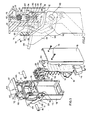
- An electronic apparatus 10 is to be connected to a coaxial cable 11.
- the apparatus 10 may be a transceiver for transmitting data, while the cable 11 is part of a data transmission local area network, for example an arbitration network operating in accordance with a protocol known in the art by the commercial name "Ethernet".
- an arbitration network operating in accordance with a protocol known in the art by the commercial name "Ethernet”.
- such a network includes a coaxial cable which runs through the locations served and allows connection of the various work stations or terminals through a corresponding transceiver 10 at any point on the cable 11.
- the transceiver 10 is constituted essentially by a logic circuit on a card 12 which also carries the respective electrical supply and includes an interface constituted by a plurality of terminals to which the terminals of the work station are connection by a connector 14 (Fig. 1).
- the card 12 is fixed to an insulating block 15 of a support for the elements for connecting to the cable 11, by means of a pair of screws 16 (Fig. 1).
- the block 15 is fixed to an insulating support 17 which constitutes the fixed frame of the device.
- the block 15 and the support 17 are preferably of plastics material loaded with glass, or of acetal resin.
- the support 17 and the card 12 are covered by a security box , of self-extinguishing resin for example.
- the coaxial cable 11 is constituted by a central conductor 19 (Fig. 2) of copper having a well defined diameter, for example about 2.2 mm, which is sheathed by a first layer 20 of dielectric material, or insulation, with a thickness of about 2 mm.
- the cable 11 is moreover screened by a braid 21, for example of copper, which is in turn covered by an outer sheath 22 which is also insulating.
- the block 15 constitutes a first jaw having a semi-cylindrical seat 23 for the cable 11.
- the block 15 is adapted to be accommodated in a space 24 in the support 17 so as to leave a space between its left-hand surface 25 and a pair of shoulders 26 (Fig. 1) of the support 17.
- the block 15 is provided with three transverse slots 27, 28 and 29 (Fig. 3).
- a metal strip 31 which is latched against a shoulder 32 of the slot 27 by the action of a resilient bent tab 33.
- the strip 31 has a bent tab 34 which supports a pair of electrical connection elements, each constituted by a needle 36 of, for example, spring steel.
- the two needles 36 (Fig. 4) are held parallel with one another at a distance slightly less than the diameter of the central conductor 19.
- the strip 31 carries a pair of pins 37 and 38 which are aligned vertically and are each provided with a stop neck for the needles 36.
- a pair of pins 40 aligned horizontally on the strip 31 are adapted to act as pivots for the i needles 36 when they are urged to bend outwards, as will be better seen from the following.
- the strip 31 includes an appendage 41 which is soldered to a terminal 42 (Fig. 1) of the printed circuit on the card 12.
- the needles 36 (Fig. 4) end at the top with a conical point and having a portion 43 which is partly prismatic, i.e. is constituted by two plane faces at 90°, for engaging the conductor 19 with the angle between the two plane faces.
- Each needle 36 also has a portion 44 covered with a layer of insulation to prevent electrical contact between the braid 21 and the needles 36.
- the neck of the pin 38 has a diameter slightly larger than that of the pin 37, while each needle 36 is provided with a channel 45 which engages in the neck of the pin 38 so that the two needles 36 are always kept orientated, i.e. face to face in reciprocally symmetrical position.
- the two slots 28 and 29 are equidistant from the slot 27.
- another metal strip 46 is located which is held in position by a resilient tab 47 engaged with a shoulder48 of the block 15.
- the strip 46 is provided with three lower bent tabs 49 and three vertical tabs 50 between which a contact element 51 for connecting the circuit of the card 12 to the braid 21 of the cable 11 is engaged.
- Each element 51 is for example of spring steel and has the form of a U which forms two needles 52 each ending with an obliquely shaped tip 53.
- the two needles 52 are mutually spaced by slightly less than the diameter of the braid 21 so that they are adapted to penetrate the outer insulation 22 and to come into contact with the braid 21.
- Each strip 46 is provided with an appendage 54 adapted to be soldered to a suitable terminal 56 of the card 12 (Fig. 1).
- the slots 27, 28 and 29 are extended downwards to allow removal of the strips 31,46 by operation of a tool on the tabs 33, 47.
- the connection device includes another jaw 61 (Fig. 1) complementing the jaw 15 and provided with a semi-cylindrical seat 62 (Fig. 2).
- the jaw 61 includes a vertical appendage 63 which is guided vertically between the two shoulders 26 of the support 17 and the surface 25 of the block 15 so that the jaw is guided to move parallel to them.
- the jaw 61 is provided below with two appendages 64 disposed at the two sides of the block 15 to facilitate the positioning of the device on the cable 11 before connection and to allow extraction of the needles 36 and 52 from the cable 11 when disconnection is desired.
- the jaw 61 is actuated by a pair of connecting rods 66 and a two-position lever 67.
- This is constituted by two arms 68 connected by a crossbar 69 and pivoted on two coaxial pins 70 carried by the support 17.
- the pivot 71 for the connecting rods 66 on the arms 68 of the lever 67 is disposed in such a position that, on rotation of the lever 67 from the open position of Fig. 2 to the closed position outlined in Fig. 2, it is carried over dead centre i.e. beyond the conjunction of the centre of the pins 70 with the pivot 72 of the connecting rods 66 on the jaw 61 so that the closed position is made stable.
- the transceiver 10 can be connected to any point of the cable 11 accessible from outside.
- the lever 67 in the position of Fig. 2, the jaw 61 is disposed on the cable 11 which is thus positioned between the semicylindrical recess 62 and the appendages 64.
- the lever 67 is then turned so that by means of the connecting rods 66 the jaw 15 is approached.
- the needles 36 and 52 (Fig. 4) then engage the cable 11, piercing its insulation.
- the needles 52 of each element 51 pierce the outer insulation 22 and engage the braid 21 at two diametrically opposed regions.
- the needles 36 pierce in turn the insulation 22, the braid 21, and the insulation 20, carrying the insulated portions 44 into correspondence with the braid 21.
- the needles 36 engage, with the angle of the region 43, two diametrically opposed regions of the central conductor 19 of the cable 11, which forces the two needles 36 slightly outwards, causing them to bend from the pivot pins 40.
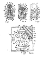
- the appendage 41 for connection to the terminal 42 is carried by a strip 75 (Fig. 5) soldered to the two needles 36.
- the strip 75 and the needles 36 are incorporated in a block 76 of plastics material such as to be able to be inserted against friction in the slot 24 of the block 15 (Fig. 3), until a tab 85 snaps under a shoulder 86.
- the needles 36 (Fig. 5) are provided with an orientating offset 77 and are arranged in the forming mould of the block 76 together with the strip 75, after the plastics material is injected.
- the block 76 has two recesses 79 which define a central appendage 80 for guiding and supporting the needles 36.
- the appendage 54 for connection to the terminal 56 (Fig. 1) of the card 12 is in turn carried by a strip 81 similar to the strip 75.
- the U-elements 51 are connected to the strip 81 by soldering and are incorporated in another block 83 of plastics material 83, in a similar manner to that seen forthe block 76.
- the block 83 has two appendages 84 for guiding and supporting needles 51 and is adapted to be inserted in the slots 28 and 29 of the block 15 until a tab 87 snaps under a shoulder 88.
- the block 15 is formed from two parts 90 and 91 (Fig. 9) of plastics material facing one another and connected by pressing by two pins 92, integral with the part 90, which engage two corresponding locations 93 in the part 91.
- the pins 92 and/or the locations 93 (Fig. 6) can be so formed as to connect the two parts by snapping together, by the example forming the pins with an axial slot and with a head with a larger diameter.
- the part 90 of the block 15 is formed with two seats 94 and 96 (Fig. 9) each adapted to receive one half of one of the blocks 83 from which the appendage 54 projects.
- Each seat 94 and 96 comprises a channel 97 for receiving a prismatic projection 98 of the block 83 (Fig. 8) and a hole 99 for allowing the appendage 54 to pass through.
- the part 91 of the block 15 is formed with two seats 101 and 102 each adapted to receive the other half of one of the blocks 83 and comprising a channel 103 for holding, through another prismatic projection 104, each block 83 in the respective seat 101 or 102.
- the needles are guided in the vicinity of the cable itself by a support generally indicated by 106 (Fig. 7), which slides perpendicularly to the seat 23 of the block 15.
- the support 106 takes the form of a hollow cylinder 107 closed at the top by a wall 108. This is provided with a slot 109 (see also Fig. 10) in which the needles 36 engage, and which therefore cannot open out during piercing.
- the cylinder 107 is moveover provided with two axial slots 111 (Fig. 7) by means of which the cylinder 107 is engaged with the receesses 79 of the block 76.
- a compression spring 112 disposed between the bottom of the recesses 79 and the wall 108 tends to push the latter towards the free ends of the needles 36.
- the assembly constituted by the block 76 with the needles 36, the cylinder 107 and the spring 112 is accommodated in two seats 113 and 114 (Fig. 9) of the two parts 90 and 91.
- These seats comprise a cylindrical portion 116 for the cylinder 109 and a prismatic portion 117 for the two ends of the block 76.
- Each portion 117 is moreover provided with a channel 118 (Fig. 7) for recieving a corresponding locking prismatic projection 119 provided on each end of the block 76.
- the part 90 is provided with a hole 120 to allow the appendage 41 of the strip 75 to pass through the part 90.
- the two seats 113 and 114 of the parts 90 and 91 are provided with two recesses 121 and 122 in which two prismatic appendages 123 (Fig. 10) of the cylinder 107 are engaged so as to prevent rotation of the cylinder 107 in the seats 113 and 114 and to determine its stroke.
- the cylinder 107 At rest the cylinder 107 is in the high position indicated in Fig. 7.
- the jaw of the connection device When the jaw of the connection device is closed, the cable 11 is pressed against the needles 36 and 52 in the seat 23 of the block 15. First the needles 36 pierce the insulation 22 of the cable 11, while the wall 108 of the cylinder 107 prevents them from spreading outwards under the laterial force. As the pressing of the cable 11 towards the seat 23 continues, the cable 11 engages the wall of the cylinder 107 and causes the latter to slide into the seats 113 and 114 against the action of the spring 112. When the needles 36 engage the conductor 19, they are guided by the wall 108 in the vicinity of the respective free ends so that these can cut into the conductor 19 as far as the position indicated in Fig. 11 without being opened out by the greater force required for such cutting, and guaranteeing excellent electrical contact.
Landscapes
- Connections By Means Of Piercing Elements, Nuts, Or Screws (AREA)
- Multi-Conductor Connections (AREA)
- Coupling Device And Connection With Printed Circuit (AREA)
Claims (14)
Applications Claiming Priority (4)
| Application Number | Priority Date | Filing Date | Title |
|---|---|---|---|
| IT6824783 | 1983-11-28 | ||
| IT68247/83A IT1159982B (it) | 1983-11-28 | 1983-11-28 | Dispositivo di collegamento di un circuito logico a un cavo coassiale |
| IT67859/84A IT1179084B (it) | 1984-08-29 | 1984-08-29 | Perfezionamenti a un dispositivo di collegamento di un circuito logico a un cavo coassiale |
| IT6785984 | 1984-08-29 |
Publications (3)
| Publication Number | Publication Date |
|---|---|
| EP0145407A2 EP0145407A2 (de) | 1985-06-19 |
| EP0145407A3 EP0145407A3 (en) | 1988-01-27 |
| EP0145407B1 true EP0145407B1 (de) | 1991-01-23 |
Family
ID=26329844
Family Applications (1)
| Application Number | Title | Priority Date | Filing Date |
|---|---|---|---|
| EP84308233A Expired - Lifetime EP0145407B1 (de) | 1983-11-28 | 1984-11-28 | Vorrichtung zum Verbinden einer logischen Schaltung mit einem koaxialen Kabel |
Country Status (3)
| Country | Link |
|---|---|
| US (1) | US4614394A (de) |
| EP (1) | EP0145407B1 (de) |
| DE (1) | DE3484009D1 (de) |
Families Citing this family (6)
| Publication number | Priority date | Publication date | Assignee | Title |
|---|---|---|---|---|
| FR2600475B1 (fr) * | 1986-06-20 | 1988-08-26 | Alsthom Cgee | Interface de liaison d'un appareillage a un cable coaxial et coupleur incorporant une telle interface |
| US5003249A (en) * | 1990-04-16 | 1991-03-26 | Bird Bruce R | Electrical power detection and indication device |
| NO312868B1 (no) * | 1994-09-28 | 2002-07-08 | Siemens Ag | Tilkoblingsinnretning for knivklemme |
| DE20001912U1 (de) * | 2000-02-03 | 2001-06-13 | Weidmüller Interface GmbH & Co, 32760 Detmold | Verbindungs- und/oder Verteilerelement für Schirmkabel |
| EP3633089B1 (de) * | 2015-06-30 | 2021-04-21 | School Juridical Person The Kitasato Institute | Detektionsvorrichtung und verfahren zur schätzung eines flüssigkeitstyps |
| WO2021118812A1 (en) | 2019-12-12 | 2021-06-17 | Commscope Technologies Llc | Dual coax network with power distribution and mid-span tap for signals and/or power from same |
Family Cites Families (5)
| Publication number | Priority date | Publication date | Assignee | Title |
|---|---|---|---|---|
| US2970184A (en) * | 1958-03-05 | 1961-01-31 | Blonder Tongue Elect | Electric cable connector |
| DE1765200A1 (de) * | 1968-04-18 | 1971-07-15 | Siemens Ag | Anschlussklemme fuer Koaxialkabel |
| US3543222A (en) * | 1969-02-24 | 1970-11-24 | Rj Communication Products Inc | Method and apparatus for coupling to a co-axial cable |
| US4261632A (en) * | 1979-04-09 | 1981-04-14 | Thomas & Betts Corporation | Coaxial cable connector |
| CA1144252A (en) * | 1980-04-10 | 1983-04-05 | Edward A. Bianchi | Coaxial tap connector |
-
1984
- 1984-11-28 DE DE8484308233T patent/DE3484009D1/de not_active Expired - Lifetime
- 1984-11-28 EP EP84308233A patent/EP0145407B1/de not_active Expired - Lifetime
- 1984-11-28 US US06/675,851 patent/US4614394A/en not_active Expired - Fee Related
Also Published As
| Publication number | Publication date |
|---|---|
| EP0145407A2 (de) | 1985-06-19 |
| US4614394A (en) | 1986-09-30 |
| DE3484009D1 (de) | 1991-02-28 |
| EP0145407A3 (en) | 1988-01-27 |
Similar Documents
| Publication | Publication Date | Title |
|---|---|---|
| USRE50502E1 (en) | Apparatus for terminating wires | |
| US3805214A (en) | Resilient electrical contact | |
| CN100429845C (zh) | 电缆端接设备及方法 | |
| EP2532052B1 (de) | Elektrische verbindungsanordnung und verfahren | |
| US3758935A (en) | Apparatus for securing wires to terminals in connectors | |
| US3835445A (en) | Electrical connecting devices for terminating cords and methods of assembling the devices to cords | |
| US6702617B1 (en) | Electrical connector with geometrical continuity for transmitting very high frequency data signals | |
| US9960549B2 (en) | Electrical connector | |
| US20100071202A1 (en) | Cable-crimping tool for connectors | |
| CA1234481A (en) | Communication plug connection tool | |
| US20080014801A1 (en) | Wire guide and connector assembly using same | |
| EP0145407B1 (de) | Vorrichtung zum Verbinden einer logischen Schaltung mit einem koaxialen Kabel | |
| CN119787013A (zh) | 具有切割片的电连接器外壳及其使用方法 | |
| GB2110886A (en) | Electrical connector member | |
| US3842392A (en) | Pre-loaded electrical connectors, assembly apparatus and method | |
| US5556307A (en) | Modular telecommunication jack assembly | |
| US4809424A (en) | Tool for preparing coaxial cable and for positioning and connection of coaxial connector therewith | |
| US4412566A (en) | Apparatus for transposing a pair of parallel and adjacent conductors into a vertical relationship | |
| US4946406A (en) | Electrical connector which requires no application tool | |
| US6824412B2 (en) | Auto-latching sliding contact mechanism enabling impedance matching between two connectors | |
| US6435898B2 (en) | Snap-in electrical conductor connecting system using conductor-cutting anvils | |
| US5238428A (en) | Round-to-flat shielded connector assembly | |
| GB2226260A (en) | Connecting an electrical connector with a cable | |
| GB2112217A (en) | An electrical connector | |
| US4209218A (en) | Insulated electrical conductor locking arrangement and method |
Legal Events
| Date | Code | Title | Description |
|---|---|---|---|
| PUAI | Public reference made under article 153(3) epc to a published international application that has entered the european phase |
Free format text: ORIGINAL CODE: 0009012 |
|
| AK | Designated contracting states |
Designated state(s): DE FR GB |
|
| PUAL | Search report despatched |
Free format text: ORIGINAL CODE: 0009013 |
|
| AK | Designated contracting states |
Kind code of ref document: A3 Designated state(s): DE FR GB |
|
| 17P | Request for examination filed |
Effective date: 19880601 |
|
| 17Q | First examination report despatched |
Effective date: 19890821 |
|
| GRAA | (expected) grant |
Free format text: ORIGINAL CODE: 0009210 |
|
| AK | Designated contracting states |
Kind code of ref document: B1 Designated state(s): DE FR GB |
|
| REF | Corresponds to: |
Ref document number: 3484009 Country of ref document: DE Date of ref document: 19910228 |
|
| ET | Fr: translation filed | ||
| PLBE | No opposition filed within time limit |
Free format text: ORIGINAL CODE: 0009261 |
|
| STAA | Information on the status of an ep patent application or granted ep patent |
Free format text: STATUS: NO OPPOSITION FILED WITHIN TIME LIMIT |
|
| 26N | No opposition filed | ||
| PGFP | Annual fee paid to national office [announced via postgrant information from national office to epo] |
Ref country code: FR Payment date: 19931110 Year of fee payment: 10 |
|
| PGFP | Annual fee paid to national office [announced via postgrant information from national office to epo] |
Ref country code: GB Payment date: 19931118 Year of fee payment: 10 |
|
| PGFP | Annual fee paid to national office [announced via postgrant information from national office to epo] |
Ref country code: DE Payment date: 19931123 Year of fee payment: 10 |
|
| PG25 | Lapsed in a contracting state [announced via postgrant information from national office to epo] |
Ref country code: GB Effective date: 19941128 |
|
| GBPC | Gb: european patent ceased through non-payment of renewal fee |
Effective date: 19941128 |
|
| PG25 | Lapsed in a contracting state [announced via postgrant information from national office to epo] |
Ref country code: FR Effective date: 19950731 |
|
| PG25 | Lapsed in a contracting state [announced via postgrant information from national office to epo] |
Ref country code: DE Effective date: 19950801 |
|
| REG | Reference to a national code |
Ref country code: FR Ref legal event code: ST |