EP0145346B1 - Reactor and susceptor for chemical vapor deposition process - Google Patents
Reactor and susceptor for chemical vapor deposition process Download PDFInfo
- Publication number
- EP0145346B1 EP0145346B1 EP84307992A EP84307992A EP0145346B1 EP 0145346 B1 EP0145346 B1 EP 0145346B1 EP 84307992 A EP84307992 A EP 84307992A EP 84307992 A EP84307992 A EP 84307992A EP 0145346 B1 EP0145346 B1 EP 0145346B1
- Authority
- EP
- European Patent Office
- Prior art keywords
- susceptor
- reactor
- wafers
- reaction vessel
- faces
- Prior art date
- Legal status (The legal status is an assumption and is not a legal conclusion. Google has not performed a legal analysis and makes no representation as to the accuracy of the status listed.)
- Expired
Links
Images




Classifications
-
- C—CHEMISTRY; METALLURGY
- C23—COATING METALLIC MATERIAL; COATING MATERIAL WITH METALLIC MATERIAL; CHEMICAL SURFACE TREATMENT; DIFFUSION TREATMENT OF METALLIC MATERIAL; COATING BY VACUUM EVAPORATION, BY SPUTTERING, BY ION IMPLANTATION OR BY CHEMICAL VAPOUR DEPOSITION, IN GENERAL; INHIBITING CORROSION OF METALLIC MATERIAL OR INCRUSTATION IN GENERAL
- C23C—COATING METALLIC MATERIAL; COATING MATERIAL WITH METALLIC MATERIAL; SURFACE TREATMENT OF METALLIC MATERIAL BY DIFFUSION INTO THE SURFACE, BY CHEMICAL CONVERSION OR SUBSTITUTION; COATING BY VACUUM EVAPORATION, BY SPUTTERING, BY ION IMPLANTATION OR BY CHEMICAL VAPOUR DEPOSITION, IN GENERAL
- C23C16/00—Chemical coating by decomposition of gaseous compounds, without leaving reaction products of surface material in the coating, i.e. chemical vapour deposition [CVD] processes
- C23C16/44—Chemical coating by decomposition of gaseous compounds, without leaving reaction products of surface material in the coating, i.e. chemical vapour deposition [CVD] processes characterised by the method of coating
- C23C16/458—Chemical coating by decomposition of gaseous compounds, without leaving reaction products of surface material in the coating, i.e. chemical vapour deposition [CVD] processes characterised by the method of coating characterised by the method used for supporting substrates in the reaction chamber
Definitions
- the present invention relates to reactors and susceptors, and more particularly to reactors and susceptors useful in a chemical vapor deposition process occurring in a radiant absorption heater system.
- III-V materials such as gallium arsenide
- other epitaxial compositions used for semiconductors, etc.
- the chemical vapor deposition process is typically performed in-any of a variety of reactors well recognized in the art, including horizontal reactors, vertical reactors, pancake reactors, and the like. Broadly, the reactors fall into two different classifications: radiant absorption heater systems (such as cold wall reactors) and oven reactors (such as hot wall reactors). Cold wall or radiant energy absorption systems are typically preferred over hot wall reactors for many reasons including their better yields and throughputs.
- the susceptor becomes hotter than the surrounding elements of the reactor vessel and consequently selectively heats up a susceptor-carried substrate for the material to be deposited. While the selective heating of the substrate relative to the other reactor vessel elements is a clear advantage of the radiant absorption heater system, economic operation of such a system clearly requires a susceptor which will efficiently use the energy being introduced.
- the present invention is directed to a susceptor for use in such a radiant absorption heater system.
- the material must be capable of efficiently absorbing the specific form of radiant energy being introduced into the reaction vessel so as to minimize the energy input required to bring the system to, and maintain it at, its usual operating temperature (this typically being in the neighborhood of 700°C or higher for the production of epitaxial III-V materials).
- the material must also be chemically inert with respect to the materials it contacts, including the source gases being introduced into the reaction vessel, and must not be a source of contamination to either the source gases, the substrate or the material being produced.
- the susceptor In a horizontal type reactor, the susceptor has the configuration of a box or rectangular parallelepiped and the reaction gases are directed from one end, across the full length thereof, towards the other end.
- the wafers to be grown are disposed on only the large upwardly-facing surface of the susceptor, typically in recesses provided for this purpose.
- the other large surface i.e., the downwardly-facing one
- the "utilized area" for a horizontal reactor is relatively low.
- the power requirement (defined as the power to bring the susceptor to reaction temperature) is 50 kilowatts, and the utilized area (defined as the surface area occupied by wafers/total susceptor surface area) is about 23%.
- the susceptor in a horizontal reactor the susceptor is usually tilted slightly upwardly in the direction of the gas flow (i.e., downstream) so that the rear or downstream wafers are exposed to fresh input gas. This minimizes the problem of depletion which occurs when a fair sized series of successive upstream wafers deplete the input gases of the reactive components and expose the most downstream wafers only to the relatively exhausted input gases.
- the tilting of the susceptor can also assist in maintaining the desired temperature profile within the reactor vessel.
- An eight sided infrared heated vertical reactor may have almost double the wafer capacity (say about 30 such wafers), but an even lower utilized area of only about 17%. As much of the surface area of its susceptor is being heated for no functional purpose, the power requirement of this type of reactor is quite high, about 115 kilowatts. Thus, a 67% increase in the wafer capacity requires a 130% increase in the power requirement. In a radio frequency heated pancake-type reactor, a slightly enhanced capacity of 21 such wafers (relative to the horizontal reactor) provides slightly enhanced utilized area of 27%, but the reactor requires 100-115 kilowatts, at least twice as much power.
- a reactor which is characterized by both a larger wafer capacity, and a low power requirement, in other words, a high utilized area. Accordingly, it is an object of the present invention to provide a reactor having a high utilized area so as to maximize its wafer capacity and minimize its power requirement.
- US-A-4 186 684 discloses a reactor for use in a chemical vapor deposition process which comprises a reaction vessel having a gas inlet and a gas outlet and defining a substantially vertical path for flow of gas between the inlet and outlet, a susceptor disposed within the reaction vessel, and heating means for the susceptor.
- the susceptor provides a converging pair of opposed faces each of which has means to receive a plurality of wafers and maintain the wafers exposed to gas flowing through the path between the gas inlet and the gas outlet, the pair of opposed faces converging towards the gas inlet.
- the reactor in accordance with the present invention has the features of the reactor of US-A-4 186 684 referred to above, and is characterized in that:
- the susceptor ends are trapezoidal in configuration, with the suscep- tortop and bottom generally being parallel and the susceptor ends also being generally parallel.
- the susceptor is configured and dimensioned so that over 30%, and preferably 40%, of its surface area may be occupied by wafers.
- Each of the opposed faces preferably extends further horizontally than vertically (in other words, is longer than it is high).
- Each of the two susceptor faces preferably has an equal number of the receiving means. More particularly, each has means to receive a vertically- spaced plurality of horizontally extending rows of wafers, each face having three rows of the receiving means, and preferably three rows of six receiving means each.
- the heating means comprises a radiant absorption heating system which may be, for example, of the radio frequency or infrared type.
- the reaction vessel preferably has the gas inlet adjacent to the top thereof and the gas outlet adjacent to the bottom thereof.
- Means may further be provided for positioning the susceptor in the reaction vessel, the susceptor having a groove in each of its ends into which the positioning means are received.
- the substantially solid susceptor of the present invention configured as a truncated wedge for use in a vertical gas flow, has a power requirement of less than 1.1 times the given power requirement despite a doubled wafer capacity.
- the reactor A comprises a reaction vessel B, a susceptor C disposed within the reaction vessel B, heating means D disposed about the reaction vessel B for heating of the susceptor C, and, optionally, means E for positioning the susceptor C in the reaction vessel B.
- the reactor A is shown with the reaction vessel B in its closed position in Figs. 2,4,8 and 9, and in its open position in Figs. 6 and 7.
- the susceptor C is configured as a truncated wedge and comprises a body having a top 10, a bottom 12; a pair of longitudinally spaced ends 14, and an upwardly converging pair of opposed faces 16.
- the susceptor top 10 and bottom 12 are generally parallel and rectangular in configuration while the susceptor eds 14 are generally parallel and trapezoidal in configuration.
- the opposed faces 16 are rectangular and, like the long edges of the susceptor ends 14, converge in a direction counter to that of the downward gas path to be described hereinafter - in other words, they converge upwardly.
- Each susceptor end 14 defines a small peripheral groove 20 extending from the bottom 12 upwardly about halfway towards the top 10, the groove being adapted to be engaged by the means E for positioning the susceptor C within the reaction vessel B.
- Each of the susceptor faces 16 has means 22 configured and dimensioned to receive a plurality of polished substrates or wafers W (two such wafers W being represented in Fig. 1) and maintain the wafers W exposed to the aforementioned gas flow path.
- Each of the two faces 16 preferably has an equal number of receiving means 22, each face being illustrated as having eighteen receiving means 22 adapted to receive a vertically spaced plurality of horizontally extending rows of wafers W. More particularly, each of the faces 16 is provided with three rows of six receiving means each. The number of rows and the number of receiving means on each row will, of course, be a function of the susceptor size, the wafer size and in general the particular application intended.
- each face extend further horizontally than vertically so that there will be relatively few rows, each containing a relatively large number of receiving means 22. While it is not required that each of the faces 16 have an equal number of receiving means 22, this is the desired goal from the standpoint of efficiency and economy.
- the wafer-receiving means 22 are preferably recesses in the faces 16. Each recess is preferably slightly oversized relative to the wafer diameter to facilitate insertion of the polished substrate or wafer and removal of the epitaxially grown wafer (actually a polished substrate with an epitaxially grown layer thereon) using tweezers, vacuum pencils or the like.
- the depth of the recesses is generally equal to or slightly less than that of the wafer so as to expose the outer surface of the wafer to the gas flow path. Alternate means recognized in the art for enabling a susceptor to receive and maintain wafers may be employed.
- the faces 16 may be substantially planar except for outwardly projecting nipples, arranged so that a plurality of nipples (generally a pair) receive and maintain each wafer in the desired position on the face.
- the nipples of course, must be made of a material compatible with that of the susceptor to avoid devitrification, peeling, contamination and the like.
- the susceptor C is substantially solid, the grooves 20 and recesses 22 in no way affecting this substantial solidity.
- the susceptor is preferably substantially homogeneous in composition and of uniform density, although variations in composition and density may be employed to alter the natural temperature profile of the susceptor, if desired.
- the susceptor C may be formed of any of the materials conventionally used for susceptors including high purity quartz, black-coated quartz, graphite, glassy carbon, silicon carbide, molybdenum, etc.
- the susceptors are formed of graphite coated with silicon carbide to effect a seal and prevent outgassing.
- the illustrated suscepter C preferably has overall dimensions of 53.34 cm by 30.48 cm (21.0 inches by 12.0 inches) with a thickness tapering from 3.27 cm (1.288 inches) at the bottom 12 to 1.27 cm (0.50 inch) at the top 10.
- Each groove 20 has a radius of 0.635 cm (0.25 inch) and a height of 15.24 cm (6.0 inches).
- the receiving means or recesses 22 are spaced at least 2.54 cm (1.00 inch) from the bottom 12, 2.64 cm (1.04 inch) from the ends 14, and 4.32 cm (1.70 inch) from the top 10.
- the recesses 22 are approximately 7.747-7.7724 cm (3.05-3.06 inches) in diameter to accommodate 7.62 cm (3 inch) diameter wafers.
- the susceptor C is disposed within the reaction vessel B, the latter comprising a upper section 30 having a gas inlet 32 adjacent the top thereof extending substantially the length of the susceptor top 10 and a lower section 34 having a gas outlet 36 adjacent the bottom thereof.
- the lower vessel section 34 is provided with four cross-members 38 which provides support for the positioning means E in a manner described hereinafter.
- the gas inlet 32 and gas outlet 36 are adapted to be connected to a gas supply (not shown) and a gas discharge or recirculation vent (not shown) respectively, so that a substantially vertical gas flow path is established between the upper inlet 32 and lower outlet 36.
- the bottom of the upper section 30 defines an outwardly extending peripheral rim or flange 40
- the top of the lower section 34 similarly defines an outwardly extending peripheral rim or flange 42.
- the lower flange 40 of the upper section 30 and the upper flange 42 of the lower section 34 may be of similar dimensions and aligned with one another vertically, the opposing faces of the flanges remain vertically spaced even in the closed position of the reaction vessel.
- the upper portion of the upper section 30 tapers slightly outwardly from the inlet 32 while the lower portion thereof defines an open-bottom chamber configured and dimensioned to enable the susceptor C to be totally received therewithin.
- the middle portion of the lower section 34 slopes inwardly so that the downward gas flow passing the cross-members 38 is concentrated and channeled into the outlet 36.
- the means E for positioning susceptor C within the reaction vessel B comprises a substantially planar rectangular support bar 50 having a pair of upstanding posts 52, one at either end thereof, and a plurality of depending spacer rods 54.
- the upstanding posts 52 are configured and dimensioned to be received within the grooves 20 of the susceptor ends 14 while the susceptor bottom 12 is resting on the top of the support bar 50. The engagement of the grooves 20 by the upstanding posts 52 stabilizes the susceptor C to prevent it from tipping over.
- the depending spacer rods 54 each have an upper section 56 and a lower section 58 of reduced diameter, the cross-members 38 of the lower reaction vessel section 34 having open- topped cylindrical apertures capable of accommodating the reduced diameter portions 58, but not the normal diameter portions 56. Accordingly, the support bar 50 is spaced by the length of the normal diameter portion 56 above the lower section 34, thereby permitting the gases which have traveled downwardly past the susceptor C and support bar 50 to sweep under the support bar 50 and into the passageways 60 (at least partially defined by the cross-members 38) leading to the gas outlet 36. (Obviously if the susceptor C or support bar 50 rested directly atop the cross-members 38, access of the gas to the passageways 60 would be blocked.)
- the reaction vessel B and the positioning means E are both preferably made of clear fused quartz.
- Conventional heating means D are disposed about the reaction vessel, particularly the upper section 30 thereof, for heating of the susceptor C disposed within the reaction vessel B.
- the heating system is of the radiant absorption variety wherein radiant energy in the form of radio frequency (RF), infrared (IR) or microwave energy is projected from outside into the reactor vessel, where it is selectively absorbed by the susceptor C.
- RF radio frequency
- IR infrared
- microwave energy is projected from outside into the reactor vessel, where it is selectively absorbed by the susceptor C.
- radio frequency energy is utilized to heat the susceptor, the susceptor composition having been selected at least partially for its ability to absorb within this frequency.
- the reaction vessel B is provided with two sealing means: an upper sealing means 70 and a lower sealing means 74.
- the upper sealing means 70 comprises an L-shaped top plate 70a which has been milled out to receive the upper and side surfaces of the flange 40 at the bottom of the upper reaction vessel section 30 and a planar bottom plate 70b which covers the lower surface of the flange 40 and extends partially therebeyond.
- the bottom plate 70b is secured to the top plate 70a, for example, by fastening means such as screws 71 (see Fig. 2) so that flange 40 is trapped therebetween.
- the lower sealing means 74 is comprised of an L-shaped bottom plate 74a and a planar top plate 74b.
- the bottom plate 74a has been milled out to receive the lower and side surfaces of the flange 42 at the top of the lower reaction vessel section 34 while the top plate 74b covers the upper surfaces of the flange 42 and extends therebeyond.
- the top plate 74b is secured to the bottom plate 74a by fastening means, for example, by screws 71 (see Fig. 2) so that flange 42 is trapped therebetween for movement therewith.
- a pair of laterally spaced gasket means such as O-rings 72, are disposed about the flange 42 to effect a gas-tight seal between the upper surface of the flange 42 and the lower surface of top plate 74b and between the lower surface of the flange 42 and the upper surface of bottom plate 74a.
- the planar top plate 74b of the lower sealing means 74 carries an additional gasket means, such as an O-ring 73, in a groove on its upper surface, gasket means 73 forming a seal between the bottom plate 70b of the upper sealing means 70 and the top plate 74b of the lower sealing means 74 (and thus between the flanges 40, 42) when the upper and lower reaction vessel sections 30, 34 are in the closed position. Even when the vessel B is in the closed position, the flanges 40, 42 are separated by the combined thicknesses of the bottom plate 70b and top plate 74b.
- the sealing means 70, 74 may be made of stainless steel or other material compatible with the quartz with which it comes into contact.
- the heating means D is wrapped in coils about the length of the upper reaction vessel section 30 (which is disposed about the susceptor C when the reaction vessel B is in the closed position)
- the upper section 30, heating means D, and upper sealing member 70 are fixed in position - for example, by securing the top plate 70a to a fixed frame 76, such as the housing for the reactor A, with fasteners such as screws 75 (see Fig. 2).
- the heating means D, upper reaction vessel section 30, and upper sealing member 70 form a single stationary sub-assembly- whose position is determined by fixed member 76.
- the lower reaction vessel section 34, positioning means E, susceptor C (including any wafers W carried thereby), and the lower sealing member 74 are secured to a movable carriage 78 to form a movable sub-assembly - for example, by securing the bottom plate 74a to the movable carriage 78 with fasteners such as screws 75 (see Fig. 2).
- the movable sub-assembly is capable of being withdrawn from the fixed sub- assembly, by a downward movement in the direction of the arrows of Figs.
- the vertical motion of the movable carriage 78 which supports the lower sealing member 74 may be manual or mechanical depending upon the degree of automation desired for the operation.
- the fixed frame 76 and movable carriage 78 do not contact the quartz of the reaction vessel B and hence may be formed of ordinary steel plate.
- the fixed frame 76 may be secured to the upper sealing member 70 and the movable carriage 78 may be secured to the lower sealing member 74 by any of the fastening techniques conventional in the art.
- the two sections 30, 34 of the reaction vessel B are in closed position, as illustrated in Figs. 2, 4 and 8-9. Their respective flanges 40, 42 are separated by the intermediate sealing plates 70b, 74b which serve to preclude the escape of gases from the reaction vessel.
- Source gases appropriate for the particular CVD reaction contemplated are introduced along the full length of the gas inlet 32 in the upper reaction vessel section 30. The gas is passed downwardly, being split into two streams by the wedge-shaped susceptor C.
- the lower wafers extend further outwardly from the mid-plane of the susceptor C than the upper wafers, and because there are only three rows of wafers in all, the lower wafers are exposed to relatively fresh input gases, thereby minimizing or completely avoiding the common depletion problem.
- the unused portions of the two gas streams recombine below the crossbar 50 and eventually enter the passageways 60 of the lower reaction vessel section 34 on their way to the gas outlet-36.
- the gas flow path is indicated by the arrows of Figs. 8 and 9.
- the movable carriage 78 is transported in the direction of the arrows of Figs. 6-7, thereby displacing downwardly the entire movable sub-assembly (comprising the susceptor C, positioning means E, lower reaction vessel section 34 and the lower sealing member 74) and so "opening" the reactor.
- the movable carriage 78 is raised into the position indicated in Figs. 2, 4 and 8-9, thereby displacing upwardly the entire movable subassembly to the illustrated position and so "closing" the reactor.
- the "utilized area" of a susceptor defined as the percentage of the susceptor surface area occupied by wafers (or potentially occupied by wafers when it is fully loaded), is a measure of its efficiency.
- the illustrated susceptor C of the present invention can accommodate 36 wafers, each having a 7.62 centimeter (3.0 inch) diameter.
- the surface area of the susceptor, excluding the grooves 20 and recesses 22 (assuming faces 16 to be planar), is 3,604 centimeters square (558.8 inches square) so that the utilized area is 45%.
- the wafer capacity is only half (18 wafers) so that the utilized area is only 23%.
- a pancake type reactor with a susceptor of roughly similar dimensions may have a slightly greater wafer capacity (21 wafers) than the horizontal reactor, and a roughly comparable utilized area of 27%.
- a vertical type reactor utilizes a susceptor of high surface area (since the susceptor is generally a hollow polygon) and may accommodate only 30 wafers on a surface area 8225 cm 2 to give a very low utilized area of 17%.
- the wedge shaped susceptor of the present invention has twice the wafer capacity of a rectangular parallelepiped or box-shaped susceptor having dimensions equal to the average corresponding dimensions of the susceptor of the present invention. (This follows logically from the fact that both faces of the susceptor of the present invention may be utilized for bearing wafers, rather than just one face.) Because the overwhelmingly largest portion of the energy requirement of a reactor vessel is the energy required to bring the susceptor up to temperature, with only a minute fraction of the energy actually being utilized to bring the wafers themselves up to temperature, the power requirement of the illustrated susceptor C of the present invention (51 kilowatts) is, despite its doubling of the wafer capacity, less than 1.1 times the power requirement of the aforementioned box-shaped susceptor (50 kW) having dimensions equal to the average corresponding dimensions of the susceptor of the present invention.
- the conventional susceptor for use in a horizontal gas flow has a power requirement which is at least 90% that of the susceptor of the present invention, despite its having a wafer capacity which is only 50%.
- the power requirements of the previously referenced pancake and vertical reactors are substantially higher, about 115 kW for the vertical reactor and 100-115 kW for the pancake reactor.
- the 51 kW power requirement of the susceptor of the present invention is only 1.02 times the 50 kW power requirement of the aforementioned box-shaped susceptor, despite a doubling of the wafer capacity (in other words, the conventional box shaped susceptor with half the wafer capacity has a power requirement which is 98% that of the susceptor of the present invention).
- Both the reactor of the present invention and the reactor of the conventional box-shaped susceptor have the same power ratio of 14.17 watts per CM 2 ("power ratio" being defined as the power requirement divided by the susceptor area).
- the problem of depletion is avoided or mitigated by two separate factors in the present invention.
Landscapes
- Chemical & Material Sciences (AREA)
- General Chemical & Material Sciences (AREA)
- Chemical Kinetics & Catalysis (AREA)
- Engineering & Computer Science (AREA)
- Materials Engineering (AREA)
- Mechanical Engineering (AREA)
- Metallurgy (AREA)
- Organic Chemistry (AREA)
- Chemical Vapour Deposition (AREA)
Description
- The present invention relates to reactors and susceptors, and more particularly to reactors and susceptors useful in a chemical vapor deposition process occurring in a radiant absorption heater system.
- Chemical vapor deposition processes are currently used to produce a variety of high purity materials and are of special utility in the production of III-V materials (such as gallium arsenide) and other epitaxial compositions used for semiconductors, etc.
- The chemical vapor deposition process is typically performed in-any of a variety of reactors well recognized in the art, including horizontal reactors, vertical reactors, pancake reactors, and the like. Broadly, the reactors fall into two different classifications: radiant absorption heater systems (such as cold wall reactors) and oven reactors (such as hot wall reactors). Cold wall or radiant energy absorption systems are typically preferred over hot wall reactors for many reasons including their better yields and throughputs.
- In the oven reactor, all of the equipment associated with the process is heated more-or-less to the reaction temperature of the source gases, which then deposit the material to be formed not only on the intended substrate, but also, for example, on the walls of the reactor vessel, thereby wasting both energy and the source materials, creating cleaning problems and, when different source materials are to be used for successive runs, presenting contamination problems between runs. By way of contrast, in a radiant absorption heating system, radiant energy in the form of radio frequency (RF), infrared (IR) or microwave energy is projected from outside the reactor vessel into the reactor vessel where it is selectively absorbed by a susceptor. As the energy is absorbed by the susceptor, the susceptor becomes hotter than the surrounding elements of the reactor vessel and consequently selectively heats up a susceptor-carried substrate for the material to be deposited. While the selective heating of the substrate relative to the other reactor vessel elements is a clear advantage of the radiant absorption heater system, economic operation of such a system clearly requires a susceptor which will efficiently use the energy being introduced. The present invention is directed to a susceptor for use in such a radiant absorption heater system.
- Various considerations severely restrict the selection of material for use as a susceptor. Clearly the material must be capable of efficiently absorbing the specific form of radiant energy being introduced into the reaction vessel so as to minimize the energy input required to bring the system to, and maintain it at, its usual operating temperature (this typically being in the neighborhood of 700°C or higher for the production of epitaxial III-V materials). Obviously the material must also be chemically inert with respect to the materials it contacts, including the source gases being introduced into the reaction vessel, and must not be a source of contamination to either the source gases, the substrate or the material being produced. When heated to the temperatures typically encountered by susceptors (often in excess of 1,000°C), most materials outgas - that is, they release from within gases which act as a source of contamination for the source gases, the substrates, and the material to be deposited, thereby introducing elements foreign to the desired reaction and resulting in an inferior end- product. Finally, use of the material must be economically feasible in the quantities required for susceptor use.
- In a horizontal type reactor, the susceptor has the configuration of a box or rectangular parallelepiped and the reaction gases are directed from one end, across the full length thereof, towards the other end. The wafers to be grown are disposed on only the large upwardly-facing surface of the susceptor, typically in recesses provided for this purpose. The other large surface (i.e., the downwardly-facing one) does not carry any wafers at all and is used solely for support of the susceptor. As the four sides of the susceptor do not carry any wafers, the "utilized area" for a horizontal reactor is relatively low. For example, a susceptor having a surface area of approximately 3,528 CM 2 (547.1 in.2) can be used for 18 wafers of 7.62 cm (three inch) diameter, disposed in three longitudinal rows of six wafers each. The power requirement (defined as the power to bring the susceptor to reaction temperature) is 50 kilowatts, and the utilized area (defined as the surface area occupied by wafers/total susceptor surface area) is about 23%.
- Actually, in a horizontal reactor the susceptor is usually tilted slightly upwardly in the direction of the gas flow (i.e., downstream) so that the rear or downstream wafers are exposed to fresh input gas. This minimizes the problem of depletion which occurs when a fair sized series of successive upstream wafers deplete the input gases of the reactive components and expose the most downstream wafers only to the relatively exhausted input gases. The tilting of the susceptor can also assist in maintaining the desired temperature profile within the reactor vessel.
- Other reactor types are subject to similar deficiencies. An eight sided infrared heated vertical reactor may have almost double the wafer capacity (say about 30 such wafers), but an even lower utilized area of only about 17%. As much of the surface area of its susceptor is being heated for no functional purpose, the power requirement of this type of reactor is quite high, about 115 kilowatts. Thus, a 67% increase in the wafer capacity requires a 130% increase in the power requirement. In a radio frequency heated pancake-type reactor, a slightly enhanced capacity of 21 such wafers (relative to the horizontal reactor) provides slightly enhanced utilized area of 27%, but the reactor requires 100-115 kilowatts, at least twice as much power. Thus the need remains for a reactor which is characterized by both a larger wafer capacity, and a low power requirement, in other words, a high utilized area. Accordingly, it is an object of the present invention to provide a reactor having a high utilized area so as to maximize its wafer capacity and minimize its power requirement.
- US-A-4 186 684 discloses a reactor for use in a chemical vapor deposition process which comprises a reaction vessel having a gas inlet and a gas outlet and defining a substantially vertical path for flow of gas between the inlet and outlet, a susceptor disposed within the reaction vessel, and heating means for the susceptor. The susceptor provides a converging pair of opposed faces each of which has means to receive a plurality of wafers and maintain the wafers exposed to gas flowing through the path between the gas inlet and the gas outlet, the pair of opposed faces converging towards the gas inlet.
- The reactor in accordance with the present invention has the features of the reactor of US-A-4 186 684 referred to above, and is characterized in that:
- the susceptor is configured as a substantially solid truncated wedge which comprises a top, a bottom, a pair of longitudinally spaced ends and the aforementioned converging pair of opposed faces; and in that:
- the heating means for the susceptor are disposed about the reaction vessel.
- In a preferred embodiment, the susceptor ends are trapezoidal in configuration, with the suscep- tortop and bottom generally being parallel and the susceptor ends also being generally parallel. The susceptor is configured and dimensioned so that over 30%, and preferably 40%, of its surface area may be occupied by wafers. Each of the opposed faces preferably extends further horizontally than vertically (in other words, is longer than it is high). Each of the two susceptor faces preferably has an equal number of the receiving means. More particularly, each has means to receive a vertically- spaced plurality of horizontally extending rows of wafers, each face having three rows of the receiving means, and preferably three rows of six receiving means each.
- The heating means comprises a radiant absorption heating system which may be, for example, of the radio frequency or infrared type. The reaction vessel preferably has the gas inlet adjacent to the top thereof and the gas outlet adjacent to the bottom thereof. Means may further be provided for positioning the susceptor in the reaction vessel, the susceptor having a groove in each of its ends into which the positioning means are received.
- Compared to a conventional substantially solid susceptor configured as a rectangular parallelepiped for use in a horizontal gas flow and having a given power requirement, the substantially solid susceptor of the present invention, configured as a truncated wedge for use in a vertical gas flow, has a power requirement of less than 1.1 times the given power requirement despite a doubled wafer capacity.
- A preferred embodiment of a reacter in accordance with the present invention will now be described with reference to the accompanying drawings, in which:
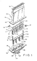
- Fig. 1 is an exploded isometric view of the reaction vessel, the susceptor and the holder, with two wafers being shown for illustrative purposes;
- Fig. 2 is a fragmentary front elevation view of the reactor assembly in a closed position;
- Fig. 3 is a fragmentary top plan view of the reactor assembly;
- Fig. 4 is a fragmentary side elevation view of the reactor assembly in a closed position;
- Fig. 5 is a fragmentary bottom plan view of the reactor assembly;
- Fig. 6 is a fragmentary front elevation view of the reactor assembly, similar to Fig. 2, but with the assembly in the open position;
- Fig. 7 is a fragmentary side elevation view of the reactor assembly, similar to Fig. 4, but with the assembly in the open position;
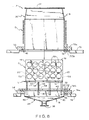
- Fig. 8 is a fragmentary sectional view of the reactor assembly taken along the line 8-8 of Fig. 4; and
- Fig. 9 is a fragmentary sectional view of the reactor assembly taken along the line 9-9 of Fig. 2.
- Referring now to the drawing and in particularto Figs. 2-9 thereof, therein illustrated is a reactor A according to the present invention. The reactor A comprises a reaction vessel B, a susceptor C disposed within the reaction vessel B, heating means D disposed about the reaction vessel B for heating of the susceptor C, and, optionally, means E for positioning the susceptor C in the reaction vessel B. The reactor A is shown with the reaction vessel B in its closed position in Figs. 2,4,8 and 9, and in its open position in Figs. 6 and 7.
- Referring now in particular to Fig. 1, the susceptor C is configured as a truncated wedge and comprises a body having a
top 10, abottom 12; a pair of longitudinallyspaced ends 14, and an upwardly converging pair ofopposed faces 16. Thesusceptor top 10 andbottom 12 are generally parallel and rectangular in configuration while thesusceptor eds 14 are generally parallel and trapezoidal in configuration. Theopposed faces 16 are rectangular and, like the long edges of thesusceptor ends 14, converge in a direction counter to that of the downward gas path to be described hereinafter - in other words, they converge upwardly. - Each
susceptor end 14 defines a smallperipheral groove 20 extending from thebottom 12 upwardly about halfway towards thetop 10, the groove being adapted to be engaged by the means E for positioning the susceptor C within the reaction vessel B. - Each of the
susceptor faces 16 has means 22 configured and dimensioned to receive a plurality of polished substrates or wafers W (two such wafers W being represented in Fig. 1) and maintain the wafers W exposed to the aforementioned gas flow path. Each of the twofaces 16 preferably has an equal number of receivingmeans 22, each face being illustrated as having eighteenreceiving means 22 adapted to receive a vertically spaced plurality of horizontally extending rows of wafers W. More particularly, each of thefaces 16 is provided with three rows of six receiving means each. The number of rows and the number of receiving means on each row will, of course, be a function of the susceptor size, the wafer size and in general the particular application intended. Nonetheless, for reasons which will be apparent hereinafter, it is preferred that each face extend further horizontally than vertically so that there will be relatively few rows, each containing a relatively large number of receiving means 22. While it is not required that each of thefaces 16 have an equal number of receiving means 22, this is the desired goal from the standpoint of efficiency and economy. - The wafer-receiving means 22 are preferably recesses in the faces 16. Each recess is preferably slightly oversized relative to the wafer diameter to facilitate insertion of the polished substrate or wafer and removal of the epitaxially grown wafer (actually a polished substrate with an epitaxially grown layer thereon) using tweezers, vacuum pencils or the like. The depth of the recesses is generally equal to or slightly less than that of the wafer so as to expose the outer surface of the wafer to the gas flow path. Alternate means recognized in the art for enabling a susceptor to receive and maintain wafers may be employed. For example, the
faces 16 may be substantially planar except for outwardly projecting nipples, arranged so that a plurality of nipples (generally a pair) receive and maintain each wafer in the desired position on the face. The nipples, of course, must be made of a material compatible with that of the susceptor to avoid devitrification, peeling, contamination and the like. - It will be appreciated that the susceptor C is substantially solid, the
grooves 20 and recesses 22 in no way affecting this substantial solidity. The susceptor is preferably substantially homogeneous in composition and of uniform density, although variations in composition and density may be employed to alter the natural temperature profile of the susceptor, if desired. The susceptor C may be formed of any of the materials conventionally used for susceptors including high purity quartz, black-coated quartz, graphite, glassy carbon, silicon carbide, molybdenum, etc. Preferably the susceptors are formed of graphite coated with silicon carbide to effect a seal and prevent outgassing. - The illustrated suscepter C preferably has overall dimensions of 53.34 cm by 30.48 cm (21.0 inches by 12.0 inches) with a thickness tapering from 3.27 cm (1.288 inches) at the bottom 12 to 1.27 cm (0.50 inch) at the top 10. Each
groove 20 has a radius of 0.635 cm (0.25 inch) and a height of 15.24 cm (6.0 inches). The receiving means or recesses 22 are spaced at least 2.54 cm (1.00 inch) from the bottom 12, 2.64 cm (1.04 inch) from theends 14, and 4.32 cm (1.70 inch) from the top 10. Therecesses 22 are approximately 7.747-7.7724 cm (3.05-3.06 inches) in diameter to accommodate 7.62 cm (3 inch) diameter wafers. - The susceptor C is disposed within the reaction vessel B, the latter comprising a
upper section 30 having agas inlet 32 adjacent the top thereof extending substantially the length of the susceptor top 10 and alower section 34 having agas outlet 36 adjacent the bottom thereof. Thelower vessel section 34 is provided with fourcross-members 38 which provides support for the positioning means E in a manner described hereinafter. Thegas inlet 32 andgas outlet 36 are adapted to be connected to a gas supply (not shown) and a gas discharge or recirculation vent (not shown) respectively, so that a substantially vertical gas flow path is established between theupper inlet 32 andlower outlet 36. - The bottom of the
upper section 30 defines an outwardly extending peripheral rim orflange 40, and the top of thelower section 34 similarly defines an outwardly extending peripheral rim orflange 42. While thelower flange 40 of theupper section 30 and theupper flange 42 of thelower section 34 may be of similar dimensions and aligned with one another vertically, the opposing faces of the flanges remain vertically spaced even in the closed position of the reaction vessel. The upper portion of theupper section 30 tapers slightly outwardly from theinlet 32 while the lower portion thereof defines an open-bottom chamber configured and dimensioned to enable the susceptor C to be totally received therewithin. The middle portion of thelower section 34 slopes inwardly so that the downward gas flow passing the cross-members 38 is concentrated and channeled into theoutlet 36. - Still referring to Fig. 1 in particular, the means E for positioning susceptor C within the reaction vessel B comprises a substantially planar
rectangular support bar 50 having a pair ofupstanding posts 52, one at either end thereof, and a plurality of dependingspacer rods 54. Theupstanding posts 52 are configured and dimensioned to be received within thegrooves 20 of the susceptor ends 14 while the susceptor bottom 12 is resting on the top of thesupport bar 50. The engagement of thegrooves 20 by theupstanding posts 52 stabilizes the susceptor C to prevent it from tipping over. - The depending
spacer rods 54 each have anupper section 56 and alower section 58 of reduced diameter, the cross-members 38 of the lowerreaction vessel section 34 having open- topped cylindrical apertures capable of accommodating thereduced diameter portions 58, but not thenormal diameter portions 56. Accordingly, thesupport bar 50 is spaced by the length of thenormal diameter portion 56 above thelower section 34, thereby permitting the gases which have traveled downwardly past the susceptor C andsupport bar 50 to sweep under thesupport bar 50 and into the passageways 60 (at least partially defined by the cross-members 38) leading to thegas outlet 36. (Obviously if the susceptor C orsupport bar 50 rested directly atop the cross-members 38, access of the gas to thepassageways 60 would be blocked.) The reaction vessel B and the positioning means E are both preferably made of clear fused quartz. - Conventional heating means D are disposed about the reaction vessel, particularly the
upper section 30 thereof, for heating of the susceptor C disposed within the reaction vessel B. The heating system is of the radiant absorption variety wherein radiant energy in the form of radio frequency (RF), infrared (IR) or microwave energy is projected from outside into the reactor vessel, where it is selectively absorbed by the susceptor C. Preferably radio frequency energy is utilized to heat the susceptor, the susceptor composition having been selected at least partially for its ability to absorb within this frequency. - The reaction vessel B is provided with two sealing means: an upper sealing means 70 and a lower sealing means 74. The upper sealing means 70 comprises an L-shaped
top plate 70a which has been milled out to receive the upper and side surfaces of theflange 40 at the bottom of the upperreaction vessel section 30 and aplanar bottom plate 70b which covers the lower surface of theflange 40 and extends partially therebeyond. Thebottom plate 70b is secured to thetop plate 70a, for example, by fastening means such as screws 71 (see Fig. 2) so thatflange 40 is trapped therebetween. A pair of laterally spaced gasket means, such as O-rings 72 made from ethylene-propylene rubber (such as that available under the tradename VITON from C.E. Conover and Co., Inc. of Fairfield, New Jersey), are disposed about theflange 40 to ensure that a gas-tight connection is made between the upper surface of theflange 40 and the lower surface oftop plate 70a and between the lower surface of theflange 40 and the upper surface ofbottom plate 70b. - In an analogous manner, the lower sealing means 74 is comprised of an L-shaped
bottom plate 74a and a planartop plate 74b. Thebottom plate 74a has been milled out to receive the lower and side surfaces of theflange 42 at the top of the lowerreaction vessel section 34 while thetop plate 74b covers the upper surfaces of theflange 42 and extends therebeyond. Thetop plate 74b is secured to thebottom plate 74a by fastening means, for example, by screws 71 (see Fig. 2) so thatflange 42 is trapped therebetween for movement therewith. As in the case of the upper sealing means 70, a pair of laterally spaced gasket means, such as O-rings 72, are disposed about theflange 42 to effect a gas-tight seal between the upper surface of theflange 42 and the lower surface oftop plate 74b and between the lower surface of theflange 42 and the upper surface ofbottom plate 74a. The planartop plate 74b of the lower sealing means 74 carries an additional gasket means, such as an O-ring 73, in a groove on its upper surface, gasket means 73 forming a seal between thebottom plate 70b of the upper sealing means 70 and thetop plate 74b of the lower sealing means 74 (and thus between theflanges 40, 42) when the upper and lowerreaction vessel sections flanges bottom plate 70b andtop plate 74b. The sealing means 70, 74 may be made of stainless steel or other material compatible with the quartz with which it comes into contact. - Because the heating means D is wrapped in coils about the length of the upper reaction vessel section 30 (which is disposed about the susceptor C when the reaction vessel B is in the closed position), the
upper section 30, heating means D, and upper sealingmember 70 are fixed in position - for example, by securing thetop plate 70a to a fixedframe 76, such as the housing for the reactor A, with fasteners such as screws 75 (see Fig. 2). Thus, the heating means D, upperreaction vessel section 30, and upper sealingmember 70 form a single stationary sub-assembly- whose position is determined by fixedmember 76. - By way of contrast, the lower
reaction vessel section 34, positioning means E, susceptor C (including any wafers W carried thereby), and thelower sealing member 74 are secured to amovable carriage 78 to form a movable sub-assembly - for example, by securing thebottom plate 74a to themovable carriage 78 with fasteners such as screws 75 (see Fig. 2). The movable sub-assembly is capable of being withdrawn from the fixed sub- assembly, by a downward movement in the direction of the arrows of Figs. 6 and 7, sufficiently to enable performance of all necessary housekeeping tasks including removal and insertion of wafers W, cleaning or replacement of the susceptor C, and even removal of the positioning means E from the lowerreaction vessel section 34. The vertical motion of themovable carriage 78 which supports thelower sealing member 74 may be manual or mechanical depending upon the degree of automation desired for the operation. - The fixed
frame 76 andmovable carriage 78 do not contact the quartz of the reaction vessel B and hence may be formed of ordinary steel plate. The fixedframe 76 may be secured to the upper sealingmember 70 and themovable carriage 78 may be secured to thelower sealing member 74 by any of the fastening techniques conventional in the art. - In use, the two
sections respective flanges intermediate sealing plates gas inlet 32 in the upperreaction vessel section 30. The gas is passed downwardly, being split into two streams by the wedge-shaped susceptor C. Because the lower wafers extend further outwardly from the mid-plane of the susceptor C than the upper wafers, and because there are only three rows of wafers in all, the lower wafers are exposed to relatively fresh input gases, thereby minimizing or completely avoiding the common depletion problem. The unused portions of the two gas streams recombine below thecrossbar 50 and eventually enter thepassageways 60 of the lowerreaction vessel section 34 on their way to the gas outlet-36. The gas flow path is indicated by the arrows of Figs. 8 and 9. - To remove the epitaxially grown wafers from the susceptors, the
movable carriage 78 is transported in the direction of the arrows of Figs. 6-7, thereby displacing downwardly the entire movable sub-assembly (comprising the susceptor C, positioning means E, lowerreaction vessel section 34 and the lower sealing member 74) and so "opening" the reactor. After replacement of the grown wafers with the new polished wafers, themovable carriage 78 is raised into the position indicated in Figs. 2, 4 and 8-9, thereby displacing upwardly the entire movable subassembly to the illustrated position and so "closing" the reactor. - The "utilized area" of a susceptor defined as the percentage of the susceptor surface area occupied by wafers (or potentially occupied by wafers when it is fully loaded), is a measure of its efficiency. The illustrated susceptor C of the present invention can accommodate 36 wafers, each having a 7.62 centimeter (3.0 inch) diameter. The surface area of the susceptor, excluding the
grooves 20 and recesses 22 (assuming faces 16 to be planar), is 3,604 centimeters square (558.8 inches square) so that the utilized area is 45%. By way of comparison, in a conventional horizontal reactor using a susceptor of approximately the same dimensions (3,528 cm2) the wafer capacity is only half (18 wafers) so that the utilized area is only 23%. A pancake type reactor with a susceptor of roughly similar dimensions (3508 cm2) may have a slightly greater wafer capacity (21 wafers) than the horizontal reactor, and a roughly comparable utilized area of 27%. A vertical type reactor utilizes a susceptor of high surface area (since the susceptor is generally a hollow polygon) and may accommodate only 30 wafers on a surface area 8225 cm2 to give a very low utilized area of 17%. - It has already been noted that the wedge shaped susceptor of the present invention has twice the wafer capacity of a rectangular parallelepiped or box-shaped susceptor having dimensions equal to the average corresponding dimensions of the susceptor of the present invention. (This follows logically from the fact that both faces of the susceptor of the present invention may be utilized for bearing wafers, rather than just one face.) Because the overwhelmingly largest portion of the energy requirement of a reactor vessel is the energy required to bring the susceptor up to temperature, with only a minute fraction of the energy actually being utilized to bring the wafers themselves up to temperature, the power requirement of the illustrated susceptor C of the present invention (51 kilowatts) is, despite its doubling of the wafer capacity, less than 1.1 times the power requirement of the aforementioned box-shaped susceptor (50 kW) having dimensions equal to the average corresponding dimensions of the susceptor of the present invention. (In other words, the conventional susceptor for use in a horizontal gas flow has a power requirement which is at least 90% that of the susceptor of the present invention, despite its having a wafer capacity which is only 50%.) The power requirements of the previously referenced pancake and vertical reactors are substantially higher, about 115 kW for the vertical reactor and 100-115 kW for the pancake reactor.
- More precisely, the 51 kW power requirement of the susceptor of the present invention is only 1.02 times the 50 kW power requirement of the aforementioned box-shaped susceptor, despite a doubling of the wafer capacity (in other words, the conventional box shaped susceptor with half the wafer capacity has a power requirement which is 98% that of the susceptor of the present invention). Both the reactor of the present invention and the reactor of the conventional box-shaped susceptor have the same power ratio of 14.17 watts per CM 2 ("power ratio" being defined as the power requirement divided by the susceptor area).
- It will be appreciated that the problem of depletion is avoided or mitigated by two separate factors in the present invention. First, the opposed susceptor faces converge in a direction counter to that of the gas flow so that at least some fresh input gas is directed to even the downstream wafers. Second, because the input gas flow is broadside to the long dimension of the susceptor, the gas stream longitudinally passes only a few wafers (e.g., two) rather than a great number (e.g., five) during its flow path from the first wafer until it reaches the last wafer.
Claims (13)
characterized in that:
Applications Claiming Priority (2)
| Application Number | Priority Date | Filing Date | Title |
|---|---|---|---|
| US553962 | 1983-11-21 | ||
| US06/553,962 US4522149A (en) | 1983-11-21 | 1983-11-21 | Reactor and susceptor for chemical vapor deposition process |
Publications (3)
| Publication Number | Publication Date |
|---|---|
| EP0145346A2 EP0145346A2 (en) | 1985-06-19 |
| EP0145346A3 EP0145346A3 (en) | 1987-08-19 |
| EP0145346B1 true EP0145346B1 (en) | 1990-10-10 |
Family
ID=24211489
Family Applications (1)
| Application Number | Title | Priority Date | Filing Date |
|---|---|---|---|
| EP84307992A Expired EP0145346B1 (en) | 1983-11-21 | 1984-11-19 | Reactor and susceptor for chemical vapor deposition process |
Country Status (4)
| Country | Link |
|---|---|
| US (1) | US4522149A (en) |
| EP (1) | EP0145346B1 (en) |
| JP (2) | JPS60138910A (en) |
| DE (1) | DE3483389D1 (en) |
Families Citing this family (50)
| Publication number | Priority date | Publication date | Assignee | Title |
|---|---|---|---|---|
| US4694779A (en) * | 1984-10-19 | 1987-09-22 | Tetron, Inc. | Reactor apparatus for semiconductor wafer processing |
| US4596208A (en) * | 1984-11-05 | 1986-06-24 | Spire Corporation | CVD reaction chamber |
| US4673799A (en) * | 1985-03-01 | 1987-06-16 | Focus Semiconductor Systems, Inc. | Fluidized bed heater for semiconductor processing |
| US4794217A (en) * | 1985-04-01 | 1988-12-27 | Qing Hua University | Induction system for rapid heat treatment of semiconductor wafers |
| JPH07105349B2 (en) * | 1985-11-08 | 1995-11-13 | フオ−カス・セミコンダクタ・システムズ・インコ−ポレイテツド | Thin film deposition method, thin film deposition apparatus, and chemical vapor deposition apparatus |
| US4976996A (en) * | 1987-02-17 | 1990-12-11 | Lam Research Corporation | Chemical vapor deposition reactor and method of use thereof |
| US5234099A (en) * | 1987-02-20 | 1993-08-10 | Mcneil-Ppc, Inc. | Coated medicaments and apparatus and methods for making same |
| US5198034A (en) * | 1987-03-31 | 1993-03-30 | Epsilon Technology, Inc. | Rotatable substrate supporting mechanism with temperature sensing device for use in chemical vapor deposition equipment |
| US4978567A (en) * | 1988-03-31 | 1990-12-18 | Materials Technology Corporation, Subsidiary Of The Carbon/Graphite Group, Inc. | Wafer holding fixture for chemical reaction processes in rapid thermal processing equipment and method for making same |
| NZ233403A (en) * | 1989-04-28 | 1992-09-25 | Mcneil Ppc Inc | Simulated capsule-like medicament |
| SE465100B (en) * | 1989-06-30 | 1991-07-22 | Inst Mikroelektronik Im | PROCEDURE AND DEVICE TO PROCESS IN A COLD WALL REACTOR |
| US5119540A (en) * | 1990-07-24 | 1992-06-09 | Cree Research, Inc. | Apparatus for eliminating residual nitrogen contamination in epitaxial layers of silicon carbide and resulting product |
| FR2678956B1 (en) * | 1991-07-12 | 1993-09-24 | Pechiney Recherche | DEVICE AND METHOD FOR DEPOSITING DIAMOND BY MICROWAVE PLASMA ASSISTED DCPV. |
| US6086680A (en) * | 1995-08-22 | 2000-07-11 | Asm America, Inc. | Low-mass susceptor |
| FI972874A0 (en) * | 1997-07-04 | 1997-07-04 | Mikrokemia Oy | Foerfarande och anordning Foer framstaellning av tunnfilmer |
| EP1036406B1 (en) | 1997-11-03 | 2003-04-02 | ASM America, Inc. | Improved low mass wafer support system |
| US6159287A (en) * | 1999-05-07 | 2000-12-12 | Cbl Technologies, Inc. | Truncated susceptor for vapor-phase deposition |
| US6149365A (en) * | 1999-09-21 | 2000-11-21 | Applied Komatsu Technology, Inc. | Support frame for substrates |
| FI118474B (en) * | 1999-12-28 | 2007-11-30 | Asm Int | Apparatus for making thin films |
| US20050170314A1 (en) * | 2002-11-27 | 2005-08-04 | Richard Golden | Dental pliers design with offsetting jaw and pad elements for assisting in removing upper and lower teeth and method for removing teeth utilizing the dental plier design |
| US20040142558A1 (en) * | 2002-12-05 | 2004-07-22 | Granneman Ernst H. A. | Apparatus and method for atomic layer deposition on substrates |
| US7537662B2 (en) | 2003-04-29 | 2009-05-26 | Asm International N.V. | Method and apparatus for depositing thin films on a surface |
| US7601223B2 (en) * | 2003-04-29 | 2009-10-13 | Asm International N.V. | Showerhead assembly and ALD methods |
| US8083853B2 (en) | 2004-05-12 | 2011-12-27 | Applied Materials, Inc. | Plasma uniformity control by gas diffuser hole design |
| US8074599B2 (en) * | 2004-05-12 | 2011-12-13 | Applied Materials, Inc. | Plasma uniformity control by gas diffuser curvature |
| US8328939B2 (en) * | 2004-05-12 | 2012-12-11 | Applied Materials, Inc. | Diffuser plate with slit valve compensation |
| US20060005771A1 (en) * | 2004-07-12 | 2006-01-12 | Applied Materials, Inc. | Apparatus and method of shaping profiles of large-area PECVD electrodes |
| US20060054090A1 (en) * | 2004-09-15 | 2006-03-16 | Applied Materials, Inc. | PECVD susceptor support construction |
| US7429410B2 (en) * | 2004-09-20 | 2008-09-30 | Applied Materials, Inc. | Diffuser gravity support |
| US20070028842A1 (en) * | 2005-08-02 | 2007-02-08 | Makoto Inagawa | Vacuum chamber bottom |
| US20070264427A1 (en) * | 2005-12-21 | 2007-11-15 | Asm Japan K.K. | Thin film formation by atomic layer growth and chemical vapor deposition |
| US20080317973A1 (en) * | 2007-06-22 | 2008-12-25 | White John M | Diffuser support |
| US8097082B2 (en) * | 2008-04-28 | 2012-01-17 | Applied Materials, Inc. | Nonplanar faceplate for a plasma processing chamber |
| US8801857B2 (en) | 2008-10-31 | 2014-08-12 | Asm America, Inc. | Self-centering susceptor ring assembly |
| TW201122148A (en) * | 2009-12-24 | 2011-07-01 | Hon Hai Prec Ind Co Ltd | Chemical vapor deposition device |
| US9441295B2 (en) * | 2010-05-14 | 2016-09-13 | Solarcity Corporation | Multi-channel gas-delivery system |
| SG11201508512PA (en) * | 2013-05-23 | 2015-12-30 | Applied Materials Inc | A coated liner assembly for a semiconductor processing chamber |
| US9972740B2 (en) | 2015-06-07 | 2018-05-15 | Tesla, Inc. | Chemical vapor deposition tool and process for fabrication of photovoltaic structures |
| US20180240684A1 (en) * | 2015-09-30 | 2018-08-23 | Tokyo Electron Limited | Substrate processing apparatus and substrate processing method |
| US9748434B1 (en) | 2016-05-24 | 2017-08-29 | Tesla, Inc. | Systems, method and apparatus for curing conductive paste |
| US9954136B2 (en) | 2016-08-03 | 2018-04-24 | Tesla, Inc. | Cassette optimized for an inline annealing system |
| US10115856B2 (en) | 2016-10-31 | 2018-10-30 | Tesla, Inc. | System and method for curing conductive paste using induction heating |
| USD920936S1 (en) | 2019-01-17 | 2021-06-01 | Asm Ip Holding B.V. | Higher temperature vented susceptor |
| US11961756B2 (en) | 2019-01-17 | 2024-04-16 | Asm Ip Holding B.V. | Vented susceptor |
| USD914620S1 (en) | 2019-01-17 | 2021-03-30 | Asm Ip Holding B.V. | Vented susceptor |
| US11404302B2 (en) | 2019-05-22 | 2022-08-02 | Asm Ip Holding B.V. | Substrate susceptor using edge purging |
| US11764101B2 (en) | 2019-10-24 | 2023-09-19 | ASM IP Holding, B.V. | Susceptor for semiconductor substrate processing |
| TWI888578B (en) | 2020-06-23 | 2025-07-01 | 荷蘭商Asm Ip私人控股有限公司 | Susceptor and reaction chamber |
| USD1031676S1 (en) | 2020-12-04 | 2024-06-18 | Asm Ip Holding B.V. | Combined susceptor, support, and lift system |
| TW202431494A (en) * | 2023-01-23 | 2024-08-01 | 美商應用材料股份有限公司 | Precursor delivery system for semiconductor device formation |
Family Cites Families (8)
| Publication number | Priority date | Publication date | Assignee | Title |
|---|---|---|---|---|
| DE1544253C3 (en) * | 1964-09-14 | 1974-08-15 | Siemens Ag, 1000 Berlin Und 8000 Muenchen | Device for the epitaxial deposition of semiconductor material |
| US3594242A (en) * | 1966-01-03 | 1971-07-20 | Monsanto Co | Method for production of epitaxial films |
| JPS4942857B1 (en) * | 1970-03-20 | 1974-11-18 | ||
| JPS5346436B2 (en) * | 1973-07-05 | 1978-12-13 | ||
| US4186684A (en) * | 1977-06-01 | 1980-02-05 | Ralph Gorman | Apparatus for vapor deposition of materials |
| JPS55110030A (en) * | 1979-02-19 | 1980-08-25 | Fujitsu Ltd | Method for vapor growth |
| JPS5670830A (en) * | 1979-11-10 | 1981-06-13 | Toshiba Corp | Vapor growth method |
| US4322592A (en) * | 1980-08-22 | 1982-03-30 | Rca Corporation | Susceptor for heating semiconductor substrates |
-
1983
- 1983-11-21 US US06/553,962 patent/US4522149A/en not_active Expired - Lifetime
-
1984
- 1984-11-19 DE DE8484307992T patent/DE3483389D1/en not_active Expired - Lifetime
- 1984-11-19 EP EP84307992A patent/EP0145346B1/en not_active Expired
- 1984-11-21 JP JP59244695A patent/JPS60138910A/en active Pending
-
1991
- 1991-06-18 JP JP1991045834U patent/JPH0710490Y2/en not_active Expired - Lifetime
Also Published As
| Publication number | Publication date |
|---|---|
| JPH0641129U (en) | 1994-05-31 |
| EP0145346A2 (en) | 1985-06-19 |
| JPH0710490Y2 (en) | 1995-03-08 |
| EP0145346A3 (en) | 1987-08-19 |
| DE3483389D1 (en) | 1990-11-15 |
| US4522149A (en) | 1985-06-11 |
| JPS60138910A (en) | 1985-07-23 |
Similar Documents
| Publication | Publication Date | Title |
|---|---|---|
| US4522149A (en) | Reactor and susceptor for chemical vapor deposition process | |
| EP0104764B1 (en) | Chemical vapor deposition apparatus and process | |
| US3796182A (en) | Susceptor structure for chemical vapor deposition reactor | |
| US4593644A (en) | Continuous in-line deposition system | |
| US9870937B2 (en) | High productivity deposition reactor comprising a gas flow chamber having a tapered gas flow space | |
| KR100415475B1 (en) | Apparatus for growing thin films onto a substrate | |
| JPS61194179A (en) | Housing for forming vapor deposition reaction chamber | |
| US20040142558A1 (en) | Apparatus and method for atomic layer deposition on substrates | |
| JPH03500064A (en) | Improvements in reaction chambers and chemical vapor deposition methods | |
| KR20010031714A (en) | Long life high temperature process chamber | |
| JPS61191015A (en) | Semiconductor vapor growth and equipment thereof | |
| JPS6015918A (en) | External isolating module | |
| US5261960A (en) | Reaction chambers for CVD systems | |
| US10718051B2 (en) | Methods for chemical vapor deposition (CVD) in a movable liner assembly | |
| US10961621B2 (en) | CVD reactor chamber with resistive heating and substrate holder | |
| EP0164928A2 (en) | Vertical hot wall CVD reactor | |
| US4547404A (en) | Chemical vapor deposition process | |
| Weyburne et al. | Design and operating considerations for a water-cooled close-spaced reactant injector in a production scale MOCVD reactor | |
| US3491720A (en) | Epitaxial deposition reactor | |
| EP0381247A2 (en) | Apparatus and method for epitaxial deposition | |
| US20190376179A1 (en) | Vapor phase film deposition apparatus | |
| KR20160135343A (en) | Device for depositing nanotubes | |
| CA2486662C (en) | Vapor-phase growth apparatus | |
| JPH04356915A (en) | Gas source cell | |
| EP2045373B1 (en) | Epitaxial reactor for the large-scale production of wafers |
Legal Events
| Date | Code | Title | Description |
|---|---|---|---|
| PUAI | Public reference made under article 153(3) epc to a published international application that has entered the european phase |
Free format text: ORIGINAL CODE: 0009012 |
|
| AK | Designated contracting states |
Designated state(s): DE FR GB |
|
| PUAL | Search report despatched |
Free format text: ORIGINAL CODE: 0009013 |
|
| RHK1 | Main classification (correction) |
Ipc: C30B 25/14 |
|
| AK | Designated contracting states |
Kind code of ref document: A3 Designated state(s): DE FR GB |
|
| 17P | Request for examination filed |
Effective date: 19870909 |
|
| 17Q | First examination report despatched |
Effective date: 19890301 |
|
| GRAA | (expected) grant |
Free format text: ORIGINAL CODE: 0009210 |
|
| AK | Designated contracting states |
Kind code of ref document: B1 Designated state(s): DE FR GB |
|
| PG25 | Lapsed in a contracting state [announced via postgrant information from national office to epo] |
Ref country code: FR Effective date: 19901010 |
|
| REF | Corresponds to: |
Ref document number: 3483389 Country of ref document: DE Date of ref document: 19901115 |
|
| PGFP | Annual fee paid to national office [announced via postgrant information from national office to epo] |
Ref country code: FR Payment date: 19901126 Year of fee payment: 7 |
|
| EN | Fr: translation not filed | ||
| PLBE | No opposition filed within time limit |
Free format text: ORIGINAL CODE: 0009261 |
|
| STAA | Information on the status of an ep patent application or granted ep patent |
Free format text: STATUS: NO OPPOSITION FILED WITHIN TIME LIMIT |
|
| 26N | No opposition filed | ||
| PGFP | Annual fee paid to national office [announced via postgrant information from national office to epo] |
Ref country code: GB Payment date: 19911017 Year of fee payment: 8 |
|
| PGFP | Annual fee paid to national office [announced via postgrant information from national office to epo] |
Ref country code: DE Payment date: 19911128 Year of fee payment: 8 |
|
| PG25 | Lapsed in a contracting state [announced via postgrant information from national office to epo] |
Ref country code: GB Effective date: 19921119 |
|
| GBPC | Gb: european patent ceased through non-payment of renewal fee |
Effective date: 19921119 |
|
| PG25 | Lapsed in a contracting state [announced via postgrant information from national office to epo] |
Ref country code: DE Effective date: 19930803 |
|
| P01 | Opt-out of the competence of the unified patent court (upc) registered |
Effective date: 20230520 |