EP0145232A2 - Bremse für Schwerkraftförderer - Google Patents
Bremse für Schwerkraftförderer Download PDFInfo
- Publication number
- EP0145232A2 EP0145232A2 EP84307541A EP84307541A EP0145232A2 EP 0145232 A2 EP0145232 A2 EP 0145232A2 EP 84307541 A EP84307541 A EP 84307541A EP 84307541 A EP84307541 A EP 84307541A EP 0145232 A2 EP0145232 A2 EP 0145232A2
- Authority
- EP
- European Patent Office
- Prior art keywords
- actuator
- accumulator
- air
- valve
- retarder
- Prior art date
- Legal status (The legal status is an assumption and is not a legal conclusion. Google has not performed a legal analysis and makes no representation as to the accuracy of the status listed.)
- Ceased
Links
Images
Classifications
-
- B—PERFORMING OPERATIONS; TRANSPORTING
- B65—CONVEYING; PACKING; STORING; HANDLING THIN OR FILAMENTARY MATERIAL
- B65G—TRANSPORT OR STORAGE DEVICES, e.g. CONVEYORS FOR LOADING OR TIPPING, SHOP CONVEYOR SYSTEMS OR PNEUMATIC TUBE CONVEYORS
- B65G13/00—Roller-ways
- B65G13/075—Braking means
Definitions
- This invention relates to gravity conveyors along which articles are moved by gravity.
- the invention is particularly concerned with controlling the velocity with which the articles move under the accelerating effect of gravity.
- Various braking or retarding mechanisms have been developed for gravity conveyors over the years. These include brake pads designed to be of a length and type sufficient to substantially reduce the rate of travel of the article. Another approach has been that of rollers equipped with one or more of various types of dampening mechanisms including those of the braking type and those of the inertial type. All of these mechanisms heretofore have been characterised by one of several deficiences.
- the brake pad type has the problem of gradually decreasing efficiency as the pads wear whereby the braking affect becomes less and less over a period of time, requiring monitoring and replacement with increasing frequency.
- Another problem has been that of lack of adjustability of the system to accommodate articles of various sizes and weight and, therefore, of different acceleration characteristics.
- centrifugal type of braking mechanisms do not work properly on light weight articles. Those which have been most effective have also been generally complex and, therefore, costly. Those that rely upon a wheel as the retarding mechanism have proven to be sensitive to the irregularities of the bottom surface of the articles being conveyed. Also.such equipment does have the problem of the limited area of contact between the wheel and the article. This tends to reduce the effectiveness of the braking mechanism as well as to materially increase the incidence of wear on both the articles and on the braking mechanisms. Another problem has been that if the retarding mechanism actually stopped the article there was no means of reinitiating its forward movement without intervention such as by the article being hit by the next approaching article. This, in many cases is undesirable.
- a retarder for a gravity conveyor comprising: an article engaging brake element; a pneumatically actuated member for moving the brake element into brake force applying position when the member is activated; means for sensing the presence of an article over the brake element; a valve connected to and activated by the sensing means when the latter is contacted by an article for admitting a charge of air of predetermined volume to an actuator; the actuator having a constantly open bleed valve for discharging the charge of air from the actuator at a predetermined rate to deactivate the actuator and returning the brake element to inactive position.
- an accumulator is provided for storing the charge of air ready for release by the valve and preferably the valve has means for alternatively connecting the accumulator to the actuator and to a source of pressurised air.
- the retarder has a frame and means for detachably securing the frame to a conveyor.
- a retarder for a gravity conveyor has a frame, a movable brake element, a pneumatic actuator for moving the brake element and means for sensing the presence of an article on the conveyor adjacent the brake element, the retarder characterised in that a pneumatic accumulator and a valve are mounted on the frame and engaged by the sensor, means connect the valve to a source of compressed air and to the accumulator and the actuator; the valve normally connecting the accumulator to the air source and isolating the actuator from the accumulator, the valve when the sensor is engaged by an article shifting to islolate the accumulator from the source and connect it to the actuator to shift the brake element into article braking position; an air bleed on the actuator for bleeding from the actuator at a predetermined rate the charge of air received from the accumulator to deactivate the brake element.
- a retarder for a gravity conveyor characterised in that it comprises a frame, an article engaging brake element in the form of a plate having a free end and pivotally mounted at its other end to the frame; a pneumatically operated actuator mounted on the frame beneath the free end of the brake plate for lifting the free end of the plate; an accumulator for air under pressure; a valve connected to the accumulator and the actuator and to a source of air under pressure; the valve normally connecting the accumulator to the source of air under pressure and isolating the actuator from the accumulator; an article sensor connected to the valve for shifting the valve when tripped by an article to islolate the accumulator from the source of pressurised air and to connect the accumulator to the actuator; the actuator having a constantly open bleed orifice for releasing air therefrom for deactivating the actuator at a predetermined rate by releasing the charge of pressurised air received from the accumulator.
- a preferred embodiment provides means for supporting the retarder on a conveyor with the brake element, when the actuator is retracted, in article disengaged position.
- the conveyor is equipped with a plurality of parallel axles, the means for supporting the retarder on the conveyor being openings in the frame for engaging over and detachably supporting the retarder on a pair of adjacent axles.
- a particular embodiment has the frame of the retarder detachably secured to a conveyor having a plurality of conveyor wheels forming a conveying surface, the wheels being mounted on an axle extending transversely of the conveyor, and the means for detachably securing the frame to the conveyor being hook elements on the frame for interengaging with at least a pair of the axles.
- An alternative embodiment has the frame of the retarder detachably secured to a conveyor having a plurality of rollers forming a conveying surface, a cradle having rods extending transversely of the conveyor, and the means for detachably securing the frame to the conveyor being hook elements on the frame for interengaging with the rods for supporting the retarder below the rollers.
- a preferred embodiment provides that one or both of a pressure valve mounted between the valve and the source of air or the air bleed means discharge are adjustable.
- the invention provides a compact, self-contained braking unit equipped with an accumulator.
- the accumulator is automatically charged whenever the mechanism is inoperative.
- the accumulator is automatically connected to the braking actuator which shifts a braking plate or shoe into active position to apply a braking force to the article and thereby slow it down.
- the actuator for the brake or shoe is equipped with a bleed, the size and volume of which is gauged to apply the brake for a predetermined length of time such that the brake will not completely halt forward motion of the article but will reduce its velocity to that which is necessary for the proper operation of the mechanism. Even if all forward movement of the article is halted, the automatic retraction of the brake will release the article to resume forward movement.
- the braking force applied to the article can be adjusted to that needed to control effectively the velocity of the article's motion.
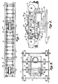
- the numeral 10 identifies a typical gravity conveyor having side rails 11 interconnected at spaced intervals by cross members 12.
- the conveyor is equipped with axles 13 mounted to the rails for rotatably supporting the conveyor wheels 14 forming the transport surface.
- Such an arrangement is of conventional construction for a gravity wheel conveyor.
- the braking mechanism of this invention consists of independent units mounted in the conveyor at spaced intervals along the length of the conveyor.
- Each of the braking units 20 includes an elongated U-shaped frame 21.
- the frame has a pair of upwardly extending sides 22 connected by a bottom web 23.
- One end of the bottom web is sheared from the sides and folded downwardly to form a depending flange 24.
- a second flange 28 depends from the opposite end of the bottom web.
- Each of the sides has a pair of L-shaped slots 25 and 25a.
- Each slot has a vertically extending portion which opens through the top of the side and:a horizontal portion extending parallel to the bottom of the frame.
- the horizontal leg portions of the slots 25 and 25a extend in opposite directions from the vertical portions of the slots, with the horizontal portions extending towards one another. Further, the horizontal portion of the slot 25a is longer than the horizontal portion of the slot 25.
- the frame can be supported on the existing axles 13 for the wheels 14 by first passing the slot 25a over one of the axles 13 and then shifting the unit to the right as it is illustrated in Figure 2 until it can be passed around the second axle. The unit can then be shifted to the left as illustrated in Figure 2 until one of the axles is seated against the end of the horizontal portion of the slot 25. This locks the braking unit frame to the conveyor. The forces of articles approaching from the right as illustrated in Figure 2 will tend to try to shift the unit to the left with the engagement between the shaft and the blind end of the slot 25 preventing the unit from-disengaging the-shafts.
- a valve 30 Mounted on the depending flange 24 is a valve 30.
- the operation of the valve is controlled by a sensor having an arm 31, the upper portion of which extends up above the surface of the conveyor into the path of articles moving along the conveyor.
- the sensor arm is secured to a pivot plate 32 by a bolt 33 ( Figure 2 and 6).
- the pivot plate 32 is pivotally supported on a pin 34.
- the lower end of the pivot plate is bent upwardly to provide a seat for a rod 35.
- a spring clip type anchor bracket 36 ( Figure 6) secures both the pin 34 and the rod 35 and prevents them from disengaging the pivot plate.
- the sensor arm 32 is biased into a normally erected position by a spring 37 secured to the rod 35 at one end and the flange 28 at the other end.
- a brake plate 40 Also pivotally mounted to the frame on the same pin 34 is a brake plate 40.
- the brake plate overlies the top of the braking unit and has a free end 41 opposite from the pin 34.
- the free end is substantially at the opposite end of the frame 21.
- the free end 41 has a downwardly depending leg having a foot piece 42 which is reversely bent to be parallel to the top surface of the plate.
- the foot piece extends beneath the axle 13 supporting the frame and thereby acts as a stop limiting upward movement_of the plate 40.
- the foot piece or shoe 42 rests on a pneumatically expandable actuator 44.
- the actuator 44 is fastened to the bottom web 23 of the frame, preferably midway between the sides of the frame.
- a pneumatic accumulator 45 Suspended below the frame and mounted to the depending flange 28 at the end of the frame opposite from the flange 24 is a pneumatic accumulator 45.
- the accumulator is connected to the valve 30 by a conduit 46.
- the valve 30 is connected to a source of air under pressure by a conduit 47 and is connected to the actuator 44 by a conduit 48.
- the valve- 30 has a central spool 50 spring biased to shift from the retracted position illustrated in Figure 2 to an extended position when the sensor 31 is shifted away from it.
- the valve 30 connects the compressed air supply 47 to the accumulator 45.
- the accumulator is isolated from the compressed air supply 47 and is connected through the lines 46 and 48 to the actuator 44. This causes the actuator to expand, lifting the end 41 of the brake shoe 40 into frictional engagement with either the article or the roller overlying the brake unit and depressing the sensor 31.
- the actuator 44 has a bleed 51 which is always open. Since the valve 30, when actuated, has isolated the accumulator 45 from its source of compressed air, the only air for operating the actuator is that which was contained in the accumulator. When this supply of air has been bled off by the bleed valve 51, the actuator will retract causing the brake shoe 40 to retract by its own weight and disengage the article. Thus, the article, its forward velocity reduced or completely stopped, is released to resume forward motion.
- the rate at which the air escapes through the bleed valve 51 can be adjusted by means of screw 52 which can be made to increase or decrease the rate of escape of the air from the actuator.
- the brake once the charge of air delivered to it from the accumulator has been exhausted, will remain inoperative indefinitely so long as the sensor 31 remains depressed.
- the actuator will once more be isolated from the accumulator and the accumulator will be recharged by the compressed air source ready for the next actuation. It will be observed that the embodiment of the invention illustrated in Figures 1 to 3 will operate irrespective of the direction of movement of the articles.
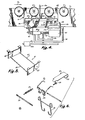
- Figures 4 and 5 illustrate a modification of the invention adapting it for use on roller conveyors.
- the unit is mounted beneath the conveyor rollers 60 forming the transport surface of the conveyor by suspension from a pair of rods 62 of a cradle or frame 61 which extend between end brackets 63 ( Figure 5) designed to be hung on the side rails 11 of the conveyor.
- the frame can be installed simply by removing a pair of the rollers 60 which are reinstalled after the frame is seated. This is a_relatively simple procedure_since the axles of the roller are seated in vertical slots in the frame.
- the brake lever 40 has a high friction pad 64 for engaging one of the rollers to provide the necessary braking action.
- the sensor 31a is reshaped to project above the surface of the rollers 60 whereby it will be depressed by an article moving in the direction of arrow B ( Figure 4).
- the lower end of the sensor arm 31a is rigidly secured to the bracket 32 whereby pivotal movement of the arm 31a to the right, as illustrated in. Figure 4, will cause the bracket to move away from the spring loaded spool 50 of the valve 30 permitting the valve to shift from accumulator charge to actuator activation in exactly the same way as the valve, actuator and accumulator operate in the case of the embodiment illustrated in Figure 2.
- the amount of braking force required for proper operation depends on several factors, including the weight and size of the articles being moved along the conveyor, the pitch of the conveyor, the condition of the surface contacting the conveyor transport surface and the force necessary to rotate the various rollers or wheels of the conveyor.
- This can be done in two ways.
- One of these ways is to provide a pressure control valve 100 in the compressed air supply line 47 to provide air at the most effective pressure for producing the force necessary to effect adequate frictional retardation against the article.
- this is an adjustable valve so that it can be manipulated to adapt the conveyor to the size and type of article to be transported.
- Another possibility is that of making the bleed 51 for each of the actuators variable so that the period the actuator maintains an effective braking force can be increased or decreased, depending on the amount of braking action needed. 4It is possible to utilize both means simulataneously with the adjustable valve 100 controlling the overall action of the brakes collectively and adjustment of the valve, in effect, "fine tuning" the individual braking mechanisms to assure efficient operation.
- this invention provides a braking mechanism which automatically releases after a predetermined interval, it can be set to effectively brake articles having substantial momentum by reason of their size, weight or the ease with which they move along the conveyor surface. At the same time, articles having much less momentum can be handled with adjustment of the pressure valve 100 or the bleed valve 51 because the automatic release feature assures the articles' ability to resume forward motion even though the braking force applied would have been adequate to effectively slow the movement of the heavier articles. Also because the brake lever is pushed upwardly into the path of the articles, the heavier articles press against it with greater force thus generating greater frictional resistance than is the case with the lighter articles.
- the units can be added to existing conveyors with a minimum of labour and down time interruption. Also this permits the number of units installed to be governed solely by the requirements of the particular conveyor system. Thus, the use of a packaged unit permits each installation to be customized. Once the units are hung in place, the only other installation work required is connecting them to a source of compressed air.
Landscapes
- Engineering & Computer Science (AREA)
- Mechanical Engineering (AREA)
- Rollers For Roller Conveyors For Transfer (AREA)
- Braking Arrangements (AREA)
- Warehouses Or Storage Devices (AREA)
Applications Claiming Priority (2)
| Application Number | Priority Date | Filing Date | Title |
|---|---|---|---|
| US06/548,303 US4542815A (en) | 1983-11-03 | 1983-11-03 | Air brake and retarder for gravity conveyors |
| US548303 | 1983-11-03 |
Publications (2)
| Publication Number | Publication Date |
|---|---|
| EP0145232A2 true EP0145232A2 (de) | 1985-06-19 |
| EP0145232A3 EP0145232A3 (de) | 1986-12-30 |
Family
ID=24188247
Family Applications (1)
| Application Number | Title | Priority Date | Filing Date |
|---|---|---|---|
| EP84307541A Ceased EP0145232A3 (de) | 1983-11-03 | 1984-11-01 | Bremse für Schwerkraftförderer |
Country Status (3)
| Country | Link |
|---|---|
| US (1) | US4542815A (de) |
| EP (1) | EP0145232A3 (de) |
| JP (1) | JPS60112509A (de) |
Cited By (2)
| Publication number | Priority date | Publication date | Assignee | Title |
|---|---|---|---|---|
| FR2593476A1 (fr) * | 1986-01-30 | 1987-07-31 | Sipa Soc Industrielle | Dispositif ralentisseur de palettes dans les installations de manutention par gravite |
| EP2489610A1 (de) * | 2011-02-17 | 2012-08-22 | Walter Winkler | Schwerkraft-Rollenbahn |
Families Citing this family (10)
| Publication number | Priority date | Publication date | Assignee | Title |
|---|---|---|---|---|
| US5102286A (en) * | 1986-09-18 | 1992-04-07 | Fenton E Dale | Trailer and trailer unloading system |
| US4809836A (en) * | 1987-09-08 | 1989-03-07 | Versa Corporation | Conveyor retarder |
| JPH0620741Y2 (ja) * | 1989-01-31 | 1994-06-01 | 株式会社ダイフク | ローラコンベヤ |
| JPH0346442U (de) * | 1989-09-11 | 1991-04-30 | ||
| US5490587A (en) * | 1993-10-12 | 1996-02-13 | Recot, Inc. | Gravity accumulation conveyor apparatus |
| US5810154A (en) * | 1996-06-11 | 1998-09-22 | Mannesmann Dematic Rapistan Corp. | Low actuation force article sensor for conveyor |
| US6234292B1 (en) * | 1999-08-04 | 2001-05-22 | Interroll Holding Ag | Pallet retainer for a conveyor |
| US6220418B1 (en) * | 1999-11-02 | 2001-04-24 | Ancra International, Llc. | Braking device for roller conveyor system for handling cargo |
| US6648573B1 (en) * | 2001-11-27 | 2003-11-18 | John V. R. Krummell, Jr. | Rack storage system with latching spring |
| US6763930B2 (en) | 2002-03-14 | 2004-07-20 | Rapistan Systems Advertising Corp. | Accumulation conveyor assembly |
Family Cites Families (4)
| Publication number | Priority date | Publication date | Assignee | Title |
|---|---|---|---|---|
| US2134373A (en) * | 1936-08-26 | 1938-10-25 | Western Electric Co | Conveyer |
| US3108671A (en) * | 1960-08-25 | 1963-10-29 | Western Electric Co | Inclined roller conveyor for conveying articles and controlling the rate of movement thereof |
| US3321057A (en) * | 1966-04-25 | 1967-05-23 | Rapids Standard Co Inc | Retarder for gravity conveyor |
| US3610372A (en) * | 1968-11-12 | 1971-10-05 | Koch Sons George | Pallet braking mechanism |
-
1983
- 1983-11-03 US US06/548,303 patent/US4542815A/en not_active Expired - Fee Related
-
1984
- 1984-11-01 EP EP84307541A patent/EP0145232A3/de not_active Ceased
- 1984-11-02 JP JP59230502A patent/JPS60112509A/ja active Pending
Cited By (2)
| Publication number | Priority date | Publication date | Assignee | Title |
|---|---|---|---|---|
| FR2593476A1 (fr) * | 1986-01-30 | 1987-07-31 | Sipa Soc Industrielle | Dispositif ralentisseur de palettes dans les installations de manutention par gravite |
| EP2489610A1 (de) * | 2011-02-17 | 2012-08-22 | Walter Winkler | Schwerkraft-Rollenbahn |
Also Published As
| Publication number | Publication date |
|---|---|
| JPS60112509A (ja) | 1985-06-19 |
| US4542815A (en) | 1985-09-24 |
| EP0145232A3 (de) | 1986-12-30 |
Similar Documents
| Publication | Publication Date | Title |
|---|---|---|
| US4542815A (en) | Air brake and retarder for gravity conveyors | |
| US4219115A (en) | Accumulation conveyor brake | |
| US3960262A (en) | Accumulating conveyor | |
| US5642976A (en) | Unloading device | |
| CA1063057A (en) | Pulsating gravity conveyor | |
| US4469321A (en) | Device for the delayed piling of sheets | |
| US4809836A (en) | Conveyor retarder | |
| US4383598A (en) | Conveyor control apparatus | |
| US5375689A (en) | Controlled flow gravity conveyor system and method | |
| US3730330A (en) | Sensor locking accumulator | |
| NO20020152L (no) | Anlegg til kjöring av personer fra en bergstasjon til en dalstasjon | |
| CA2639815A1 (en) | Control and regulation device for safeguarding a conveyor device, conveyor device and crane unit | |
| US4253558A (en) | Conveyor system | |
| US3156345A (en) | Motor powered accumulating conveyor | |
| US4003185A (en) | Caser apparatus | |
| US20200255227A1 (en) | Brake device for a conveyor system | |
| US4854445A (en) | Wide range accumulator conveyor | |
| EP0223441B1 (de) | Stauförderer für einen weiten Bereich | |
| US5950768A (en) | Elevator speed regulating safety equipment | |
| US2590994A (en) | Braking apparatus for roller conveyers | |
| US3642130A (en) | Modular weight-sorting assembly for conveyors | |
| US4392568A (en) | Live roller conveyor | |
| US5642799A (en) | Conveyor including a braking device | |
| US3503471A (en) | Monorail brake system | |
| US3900097A (en) | Live roller conveyor |
Legal Events
| Date | Code | Title | Description |
|---|---|---|---|
| PUAI | Public reference made under article 153(3) epc to a published international application that has entered the european phase |
Free format text: ORIGINAL CODE: 0009012 |
|
| AK | Designated contracting states |
Designated state(s): DE FR GB IT NL |
|
| PUAL | Search report despatched |
Free format text: ORIGINAL CODE: 0009013 |
|
| AK | Designated contracting states |
Kind code of ref document: A3 Designated state(s): DE FR GB IT NL |
|
| 17P | Request for examination filed |
Effective date: 19870514 |
|
| 17Q | First examination report despatched |
Effective date: 19880304 |
|
| STAA | Information on the status of an ep patent application or granted ep patent |
Free format text: STATUS: THE APPLICATION HAS BEEN REFUSED |
|
| 18R | Application refused |
Effective date: 19890226 |
|
| RIN1 | Information on inventor provided before grant (corrected) |
Inventor name: LEEMKUIL, HENDRIK |