EP0145176A2 - Electro-therapeutic device - Google Patents
Electro-therapeutic device Download PDFInfo
- Publication number
- EP0145176A2 EP0145176A2 EP84307113A EP84307113A EP0145176A2 EP 0145176 A2 EP0145176 A2 EP 0145176A2 EP 84307113 A EP84307113 A EP 84307113A EP 84307113 A EP84307113 A EP 84307113A EP 0145176 A2 EP0145176 A2 EP 0145176A2
- Authority
- EP
- European Patent Office
- Prior art keywords
- electrodes
- resistance
- housing
- low
- stimulus
- Prior art date
- Legal status (The legal status is an assumption and is not a legal conclusion. Google has not performed a legal analysis and makes no representation as to the accuracy of the status listed.)
- Granted
Links
Images


Classifications
-
- A—HUMAN NECESSITIES
- A61—MEDICAL OR VETERINARY SCIENCE; HYGIENE
- A61N—ELECTROTHERAPY; MAGNETOTHERAPY; RADIATION THERAPY; ULTRASOUND THERAPY
- A61N1/00—Electrotherapy; Circuits therefor
- A61N1/18—Applying electric currents by contact electrodes
- A61N1/32—Applying electric currents by contact electrodes alternating or intermittent currents
-
- A—HUMAN NECESSITIES
- A61—MEDICAL OR VETERINARY SCIENCE; HYGIENE
- A61H—PHYSICAL THERAPY APPARATUS, e.g. DEVICES FOR LOCATING OR STIMULATING REFLEX POINTS IN THE BODY; ARTIFICIAL RESPIRATION; MASSAGE; BATHING DEVICES FOR SPECIAL THERAPEUTIC OR HYGIENIC PURPOSES OR SPECIFIC PARTS OF THE BODY
- A61H39/00—Devices for locating or stimulating specific reflex points of the body for physical therapy, e.g. acupuncture
- A61H39/002—Using electric currents
Definitions
- This invention relates to an electro-therapeutic device, and more specifically to an electro-therapeutic device capable of detecting electrically low-resistance points such as acupuncture points or biologically active trigger points by applying the device to the surface of the skin and capable of stimulating them for a short period.
- an electro-therapeutic device in accordance with the present invention, includes a hand held housing having a pair of electrodes disposed at one end. The electrodes are placed in contact with the skin and an electronic circuit coupled to the electrodes is capable of detecting a decrease in the resistance of the skin, thereby identifying a low-resistance point.
- the electronic circuit further includes a pulse generator which applies via the electrodes a stimulus to stimulate the identified low-resistance point.
- an electro-therapeutic device of the invention includes a housing 1 which is shaped as slenderly as a pen-and provided on its one end with a low-resistance point sensor including a center electrode 2a and an outer electrode 2b.
- the outer electrode 2b is disposed around the center electrode 2a spaced by an insulative material 4.
- Each electrode is composed of a metal such as stainless steel and is -2 to 6 mm in diameter.
- the center electrode 2a is connected through a spring contact 8 and a lead wire 10 to an IC circuit 5 including a DC amplifier, while the outer electrode 2b is connected to the same circuit 5 through a lead wire 11.
- the IC circuit 5 is powered by a battery 7 and its output is applied to a speaker 6 (or a lamp etc.).
- the IC circuit 5 is further connected to an indicator 13 including light emitting diodes (LED',s) 13a to 13e.
- the indicator 13 is constructed to indicate a resistance between the electrodes 2a and 2b, so that LED",s are turned on successively in response to a decrease of the resistance.
- all the LED's can first be turned on and turned off successively one by one with each stimulation on a low-resistance point.
- the electrodes 2a, 2b are connected to a pulse generator 12 which produces a pulse in response to an operation of a switch 3 disposed on the outside of the housing 1.
- the pulse generator 12 includes two transformers T1 , T2 , a transistor Q1 , a capacitor Cl and two diodes D 1 , D 2 as shown in Fig. 4.
- All the components including the IC circuit 5, the battery 7, the speaker 6 and the pulse generator 12 are accommodated within the housing 1, but the sound emitting portion lc of the speaker 6 appears on the surface of the housing 1.
- an operator searchs a low-resistance point by holding the housing 1 with the sensor 2 placed in contact with his or his patient's skin. A current of approximately 0.2 micro A then flows through the electrodes 2a, 2b. When the electrodes 2a and 2b are located just upon a low-resistance point, the resistance between the two electrodes decreases, for instance, from 100M ohm to 100K ohm. This decrease in resistance activates the IC circuit 5 which drives the speaker 6 and indicator 13 so that the detection of the point may be audiovisually indicated. The operator then operates the switch 3 for stimulation.
- the operating of the switch 3 causes the transistor Q 1 to be turned on, so that a current flows through the primary winding of the transformer T 1 , and a boosted current flows through the diodes D 1 , D 2 and the capacitor C 1 connected to the secondary winding thereof.
- the diodes D 1 and D 2 are made conductive or non-conductive in dependance upon the charge on the capacitor, thereby generating a pulse with a predetermined duty factor in the secondary winding. Since the secondary winding of the transformer T 1 is connected to the electrodes 2a, 2b, the pulse is applied to the low-resistance point to stimulate it.
- the stimulation can be adjusted by variable resistor R 1 which varies the pulse frequency, that is, the output energy for stimulation.
- the operation of the switch 3 at the time of detection of a low-resistance point causes an electric pulse (piezo-current about 1 micro A) to be generated, which flows through the detected low-resistance point to give a comfortable stimulation on the low-resistance point.
- the switch 3 can be automatically turned on to apply the voltage through the electrodes when a low-resistance point is located.
- Fig. 5 shows a preferred embodiment of this automatic detecting and stimulating operation.
- the detection signal is amplified through the IC circuit 5 to activate a comparator 14 with the detection displayed by the indicator 13. This causes the switch 3 to be operated to generate the pulse for stimulation by the circuit as shown in Fig. 4.
- Figs. 6 and 7 show another preferred embodiment of the device in accordance with this invention.
- the electro-therapeutic device in Fig. 6 includes a housing 21 which is shaped to be able to be attached to a user',s finger by having the finger inserted through an opening 21b at its front end, so that the user can make the detection with ease.
- the housing is provided at the top end with a low-resistance point sensor 22 including a center electrode 22a and an outer electrode 22b disposed around the electrode 22a with both the electrodes separated by an insulative material 24.
- each electrode is made of a metal such as stainless steel 2 to 6 mm in diameter.
- These two electrodes 22a, 22b are disposed very closely to form one unit, but preferably spaced away from each other at a distance shorter than at least about 3cm.
- the center electrode 22a is connected through a spring contact 8 and a lead wire 30 to an IC circuit 25, while the outer electrode 22b is connected to the same circuit 25 through a lead wire 31.
- the IC circuit 25 is powered by a battery 27 and its output is connected to a speaker 26 (and/or a lamp).
- the electrodes are also connected parallel to a series connection of a piezoelectric element 23 and a lamp 29 such as LED. All the components including the IC circuit 25, the battery 27 and the speaker 26 are accommodated within the surface 21a of the housing 21, but the sound emitting portion 21c of the speaker appears on the surface thereof.
- the user searches a low-resistance point by inserting one of his. fingers into the opening 21b with the sensor 2 placed in contact with his or his patient',s skin.
- a current of approximately 0.2 micro A flows through the electrodes 22a, 22b to the skin. If the electrodes 22a and 22b are located just upon a low-resistance point, the resistance between the electrodes decreases, for instance, from 100M ohm to 100K ohm. This decrease of resistance actuates the IC circuit 25, which then powers the speaker 26 to indicate the detection for the low-resistance point.
- the operator then actuates the piezoelectric element 23 mounted on the side of the housing 21 to make a stimulation.
- the actuation of the piezoelectric element causes the generation of a stimulus in the form of an electric pulse (piezo current of approximately 1 micro A), which flows through the electrodes 22a, 22b into the detected low-resistance point to give a comfortable stimulation thereon.
- the LED 29 is turned on for indication.
- the speaker 26 could be replaced by an optical element such as an LED to visualize the low-resistance point detection. It can also be possible to drive the piezoelectric element automatically to apply a voltage between the electrodes upon the detection as mentioned above. Further, the electrodes can be driven at the time of detection by another power source instead of the piezoelectric element.
- a stimulating power source such as a laser oscillator, infrared LED or ultrasonic generator can be used as shown in Fig. 9, in which the power source 31 driven by a power supply 30 is provided.
- the automatic or manual closing of a switch 33 upon detection by the sensor 22 causes a light or sound oscillation.
- the emitted stimulus from the oscillator 31 is led through an optical fiber 32 into the electrodes 22a, 22b arranged as one unit to stimulate the detected low-resistance point. This stimulus is so weak that there will. be no harm to the patient',s skin.
- the detection of the low-resistance point is made using very low (0.2 micro Amp.) current and will cause hardly any pain or unpleasantness to the patient. Both the detection and stimulation are performed by the same electrodes. This allows very efficient and effective treatment.
- the use of the piezoelectric element or laser oscillator as a stimulating power supply makes it possible to make a comfortable electric stimulation on the low-resistance points.
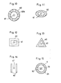
- the electrodes are shown to be coaxially and circularly arranged.
- the electrodes can be formed in any other shape.
- an outer electrode 40 can be interrupted by gaps 40a arranged in equally spaced relationship as shown in Fig. 10.
- an oval, rectangular, or triangular electrode 40 can be provided as shown in Figs. 11 to 13.
- F ig. 14 shows another embodiment in which the electrodes are constructed as two parallel stripes 40, 41.
- the electrodes 40, 41 do not always need to be exactly disposed in coaxial arrangement.
- the center or outer electrode can be disposed with a certain offset. Only the requirement is that the outer and center electrodes are closely disposed at a distance spaced away preferably less than 1 to 3 cm.
- the electrodes can be adjusted in distance.
- an adjusting screw 50 penetrating through the outer electrode 2b is provided which can reach the center electrode 2a, so that the distance between the electrodes 2a, 2b can be adjusted by adjusting the screw 50.
- the device in this embodiment includes a relatively slender housing 100 fabricated from plastic or other suitable material which is shaped to fit comfortably in the user's hand.
- a clip 111 is attached to the housing 110 to allow the electro-therapeutic device to be carried in a pocket.
- a pair of LED',s 116, 117 and switches 112, 113, 118 which allow the user to operate the device are disposed in the housing 100.
- a pair of electrodes 114, 115 are disposed at the bottom of the housing 100.
- Fig. 20 illustrates in cross section coaxial electrodes 114, 115 of the present invention.
- the coaxial electrodes are separated by an insulative material (including air) and are designed to be placed in contact with the user',s skin.
- the center electrode 115 is about 1 mm in diameter and the outer electrode 114 is about 4 mm in diameter.
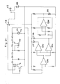
- Fig. 21 shows a schematic diagram of an electronic circuit coupled to the coaxial electrodes 114, 115.
- the electronic circuit includes a 3V DC power supply 120, which is activated by a switch 112.
- a DC 0.2 micro A current then flows to the electrodes 114, 115.
- the electrodes 114, 115 are placed over a low-resistance point, there is a resistance differential or a decrease in resistance between the two electrodes which activates amplifier 123a.
- An activated output signal from the amplifier 123a, 123b is applied to illuminate a green LED 117, to sound a buzzer 126 and to operate a buzzer circuit which includes an amplifier 123d.
- the switch 118 is depressed activating a pulse generator which includes transformers T 4 .
- the pulse amplitude of the pulse generator can be changed by switch 113 to either a higher or a lower setting.
- a user of the present device merely has to hold the housing 100 and keep the electrodes 114, 115 in contact with a portion of a human body as he moves the device over the body.
- a very weak electric current (about 0.2 micro Amp.) flows over the human skin between the center electrode 115 and the outer electrode 114.
- the electrodes 114, 115 come directly over a low-resistance point where electric resistance is much less than other areas (which varies between 100M ohm and 100K ohm), such variation in resistance is indicated by the sound of buzzer 126 and the LED 17.
- the user then pushes the switch 118 to send a pulse to the low-resistance point. The pulse is emitted between the electrodes 114, 115.
- the device of the present invention has several advantages over prior art devices.
- the entire instrument is small and lightweight and very easy to handle.
- the detection of a low-resistance point is made using very low (0.2 microamp.) current and will cause hardly any pain or unpleasantness to the patient.
- Both the detection and the stimulation are done by the same electrodes which allow very efficient and effective treatment.
- the degree of stimulation is adjustable in order to give the exact amount of required stimulation. Since both detection and stimulation are provided by the same electrodes, the construction of the instrument is very simple and also prevents the unnecessary flow of electric current to places other than the desired low-resistance points.
Abstract
Description
- This invention relates to an electro-therapeutic device, and more specifically to an electro-therapeutic device capable of detecting electrically low-resistance points such as acupuncture points or biologically active trigger points by applying the device to the surface of the skin and capable of stimulating them for a short period.
- It is well-known that an appropriate stimulation on low-resistance points of the body can give a relief from pain, relaxation or health promotion etc.. In the prior art, many electro-therapeutic devices are known which efficiently work for the low-resistance point stimulation, but conventional devices are relatively expensive, complex, bulky and generally require a trained person to operate. Moreover, the points of the body to be stimulated by such devices are very difficult for an untrained person to locate, thereby requiring a trained person or at least causing an untrained person to make a rough approximation.
- Another disadvantage of such prior art devices is that they require two separated electrodes. One of the electrodes must be held by the person to be treated and the second electrode is held and manipulated by the operator of the machine. It can be appreciated that when the person to be treated operates the prior art devices himself it presents an awkward or clumsy situation. All genuine prior art devices in this category use separate detecting and stimulating electrodes which cause electrical current to travel through the body from one electrode to the other, thereby stimulating hundreds of low-resistance points and passing through vital organ'.s tissues unnecessarily.
- Accordingly, there is a need for a simple portable electro-therapeutic device which can overcome these disadvantages, detect low-resistance points on the body, be easily efficiently operated by the user, and limit itself to stimulation of only those points required for treatment.
- It is therefore an object of the present invention to provide an easy to use portable electro-therapeutic device that allows the user of the device to treat himself.
- In accordance with the present invention, an electro-therapeutic device includes a hand held housing having a pair of electrodes disposed at one end. The electrodes are placed in contact with the skin and an electronic circuit coupled to the electrodes is capable of detecting a decrease in the resistance of the skin, thereby identifying a low-resistance point. The electronic circuit further includes a pulse generator which applies via the electrodes a stimulus to stimulate the identified low-resistance point.
- The objects and features of the present invention will become more apparent from a consideration of the following detailed description taken in conjunction with the accompanying drawings in which:
- Fig. 1 is a partially broken away front view of the device of the present invention;
- Fig. 2 is a schematic block diagram of the electric circuit for low-resistance point detection and stimulation;
- Fig. 3 is a cross-sectional view of the electrodes;
- Fig. 4 is a diagram of the electric circuit for generating a stimulating pulse;
- Fig. 5 is a schematic block diagram showing another embodiment of the electric circuit for low-resistance point detection and stimulation;
- Figs. 6 and 7 are respectively a perspective view and a bottom view showing another:embodiment of the present invention;
- Figs. 8 and 9 are respectively schematic diagrams each showing another embodiment of the electric circuit for low-resistance point detection and stimulation;
- Figs. 10 to 14 are cross-sectional views each showing another embodiment of electrodes for low-resistance point detection and stimulation;
- Fig. 15 is a cross-sectional view of another embodiment of electrodes whose distance can be adjusted;
- Figs. 16 to 19 are respectively a front view, a side view, a top view and a bottom view showing another embodiment of the device of the present invention;
- Fig. 20 is a cross-sectional view taken along the V - V line in Fig. 17; and
- Fig. 21 is a diagram of the electric circuit used in the embodiment of the device shown in Figs. 16 to 19.
- Figs. 1 and 2 show the first preferred embodiment of this invention. In Fig. 1, an electro-therapeutic device of the invention includes a
housing 1 which is shaped as slenderly as a pen-and provided on its one end with a low-resistance point sensor including acenter electrode 2a and anouter electrode 2b. Theouter electrode 2b is disposed around thecenter electrode 2a spaced by aninsulative material 4. Each electrode is composed of a metal such as stainless steel and is -2 to 6 mm in diameter. These twoelectrodes - The
center electrode 2a is connected through aspring contact 8 and alead wire 10 to anIC circuit 5 including a DC amplifier, while theouter electrode 2b is connected to thesame circuit 5 through alead wire 11. TheIC circuit 5 is powered by abattery 7 and its output is applied to a speaker 6 (or a lamp etc.). TheIC circuit 5 is further connected to anindicator 13 including light emitting diodes (LED',s) 13a to 13e. For example, theindicator 13 is constructed to indicate a resistance between theelectrodes - The
electrodes pulse generator 12 which produces a pulse in response to an operation of aswitch 3 disposed on the outside of thehousing 1. Thepulse generator 12 includes two transformers T1, T2, a transistor Q1, a capacitor Cl and two diodes D1, D2 as shown in Fig. 4. - All the components including the
IC circuit 5, thebattery 7, thespeaker 6 and thepulse generator 12 are accommodated within thehousing 1, but the sound emitting portion lc of thespeaker 6 appears on the surface of thehousing 1. - In operation, an operator searchs a low-resistance point by holding the
housing 1 with thesensor 2 placed in contact with his or his patient's skin. A current of approximately 0.2 micro A then flows through theelectrodes electrodes IC circuit 5 which drives thespeaker 6 andindicator 13 so that the detection of the point may be audiovisually indicated. The operator then operates theswitch 3 for stimulation. - The operating of the
switch 3 causes the transistor Q1 to be turned on, so that a current flows through the primary winding of the transformer T1, and a boosted current flows through the diodes D1, D2 and the capacitor C1 connected to the secondary winding thereof. The diodes D1 and D2 are made conductive or non-conductive in dependance upon the charge on the capacitor, thereby generating a pulse with a predetermined duty factor in the secondary winding. Since the secondary winding of the transformer T1 is connected to theelectrodes - Thus, the operation of the
switch 3 at the time of detection of a low-resistance point causes an electric pulse (piezo-current about 1 micro A) to be generated, which flows through the detected low-resistance point to give a comfortable stimulation on the low-resistance point. - The
switch 3 can be automatically turned on to apply the voltage through the electrodes when a low-resistance point is located. - Fig. 5 shows a preferred embodiment of this automatic detecting and stimulating operation. In Fig. 5, if a low-resistance point is detected, the detection signal is amplified through the
IC circuit 5 to activate acomparator 14 with the detection displayed by theindicator 13. This causes theswitch 3 to be operated to generate the pulse for stimulation by the circuit as shown in Fig. 4. - Figs. 6 and 7 show another preferred embodiment of the device in accordance with this invention. The electro-therapeutic device in Fig. 6 includes a
housing 21 which is shaped to be able to be attached to a user',s finger by having the finger inserted through an opening 21b at its front end, so that the user can make the detection with ease. The housing is provided at the top end with a low-resistance point sensor 22 including acenter electrode 22a and anouter electrode 22b disposed around theelectrode 22a with both the electrodes separated by aninsulative material 24. Similarly as mentioned before, each electrode is made of a metal such asstainless steel 2 to 6 mm in diameter. These twoelectrodes - The
center electrode 22a is connected through aspring contact 8 and alead wire 30 to anIC circuit 25, while theouter electrode 22b is connected to thesame circuit 25 through alead wire 31. TheIC circuit 25 is powered by abattery 27 and its output is connected to a speaker 26 (and/or a lamp). The electrodes are also connected parallel to a series connection of apiezoelectric element 23 and alamp 29 such as LED. All the components including theIC circuit 25, thebattery 27 and thespeaker 26 are accommodated within thesurface 21a of thehousing 21, but thesound emitting portion 21c of the speaker appears on the surface thereof. - In operation, the user searches a low-resistance point by inserting one of his. fingers into the
opening 21b with thesensor 2 placed in contact with his or his patient',s skin. A current of approximately 0.2 micro A flows through theelectrodes electrodes IC circuit 25, which then powers thespeaker 26 to indicate the detection for the low-resistance point. The operator then actuates thepiezoelectric element 23 mounted on the side of thehousing 21 to make a stimulation. The actuation of the piezoelectric element causes the generation of a stimulus in the form of an electric pulse (piezo current of approximately 1 micro A), which flows through theelectrodes LED 29 is turned on for indication. - The
speaker 26 could be replaced by an optical element such as an LED to visualize the low-resistance point detection. It can also be possible to drive the piezoelectric element automatically to apply a voltage between the electrodes upon the detection as mentioned above. Further, the electrodes can be driven at the time of detection by another power source instead of the piezoelectric element. - As a stimulating power source, a power source such as a laser oscillator, infrared LED or ultrasonic generator can be used as shown in Fig. 9, in which the
power source 31 driven by apower supply 30 is provided. The automatic or manual closing of aswitch 33 upon detection by thesensor 22 causes a light or sound oscillation. The emitted stimulus from theoscillator 31 is led through anoptical fiber 32 into theelectrodes - The detection of the low-resistance point is made using very low (0.2 micro Amp.) current and will cause hardly any pain or unpleasantness to the patient. Both the detection and stimulation are performed by the same electrodes. This allows very efficient and effective treatment. The use of the piezoelectric element or laser oscillator as a stimulating power supply makes it possible to make a comfortable electric stimulation on the low-resistance points.
- In the foregoing embodiments, the electrodes are shown to be coaxially and circularly arranged. However, the electrodes can be formed in any other shape. For example, an
outer electrode 40 can be interrupted bygaps 40a arranged in equally spaced relationship as shown in Fig. 10. Alternatively, an oval, rectangular, ortriangular electrode 40 can be provided as shown in Figs. 11 to 13. Fig. 14 shows another embodiment in which the electrodes are constructed as twoparallel stripes - Furthermore, the
electrodes - In each embodiment, it can be appreciated that the electrodes can be adjusted in distance. As shown Fig. 15, an adjusting
screw 50 penetrating through theouter electrode 2b is provided which can reach thecenter electrode 2a, so that the distance between theelectrodes screw 50. - Referring now to Figs. 16 to 20, there is shown another embodiment of the present invention. The device in this embodiment includes a relatively
slender housing 100 fabricated from plastic or other suitable material which is shaped to fit comfortably in the user's hand. Aclip 111 is attached to the housing 110 to allow the electro-therapeutic device to be carried in a pocket. A pair of LED',s housing 100. A pair ofelectrodes housing 100. - Fig. 20 illustrates in cross section
coaxial electrodes center electrode 115 is about 1 mm in diameter and theouter electrode 114 is about 4 mm in diameter. - Fig. 21 shows a schematic diagram of an electronic circuit coupled to the
coaxial electrodes DC power supply 120, which is activated by aswitch 112. - A DC 0.2 micro A current then flows to the
electrodes electrodes amplifier 123a. An activated output signal from theamplifier green LED 117, to sound abuzzer 126 and to operate a buzzer circuit which includes anamplifier 123d. When a low-resistance point is thus located, theswitch 118 is depressed activating a pulse generator which includes transformers T4. The pulse amplitude of the pulse generator can be changed byswitch 113 to either a higher or a lower setting. - After stimulation of the low-resistance point, skin resistance changes. This change may be sensed by the
amplifier 123c which in turn activates LED 116, and can provide an indication that the low-resistance point',s resistance has been sufficiently changed to indicate that treatment is finished. This procedure may be repeated for other low-resistance points as desired. - Thus, it can be appreciated that a user of the present device merely has to hold the
housing 100 and keep theelectrodes center electrode 115 and theouter electrode 114. When theelectrodes buzzer 126 and the LED 17. The user then pushes theswitch 118 to send a pulse to the low-resistance point. The pulse is emitted between theelectrodes - It can also be appreciated from the foregoing that the device of the present invention has several advantages over prior art devices. The entire instrument is small and lightweight and very easy to handle. The detection of a low-resistance point is made using very low (0.2 microamp.) current and will cause hardly any pain or unpleasantness to the patient. Both the detection and the stimulation are done by the same electrodes which allow very efficient and effective treatment. The degree of stimulation is adjustable in order to give the exact amount of required stimulation. Since both detection and stimulation are provided by the same electrodes, the construction of the instrument is very simple and also prevents the unnecessary flow of electric current to places other than the desired low-resistance points.
- While the invention has been described in its preferred embodiments, it is to be understood that the words which have been used are words of description rather than limitation, and that changes may be made within the purview of the appended claims without departing from the true scope and spirit of the invention in its broader aspects.
Claims (15)
Priority Applications (1)
| Application Number | Priority Date | Filing Date | Title |
|---|---|---|---|
| AT84307113T ATE34923T1 (en) | 1983-10-25 | 1984-10-17 | ELECTROTHERAPEUTIC DEVICE. |
Applications Claiming Priority (6)
| Application Number | Priority Date | Filing Date | Title |
|---|---|---|---|
| JP164090/83U | 1983-10-25 | ||
| JP16409083U JPS6071224U (en) | 1983-10-25 | 1983-10-25 | acupoint stimulator |
| JP17608583U JPS6083644U (en) | 1983-11-16 | 1983-11-16 | acupoint stimulator |
| JP176085/83U | 1983-11-16 | ||
| JP9539984U JPS6110741U (en) | 1984-06-27 | 1984-06-27 | acupoint stimulator |
| JP95399/84U | 1984-06-27 |
Publications (3)
| Publication Number | Publication Date |
|---|---|
| EP0145176A2 true EP0145176A2 (en) | 1985-06-19 |
| EP0145176A3 EP0145176A3 (en) | 1985-07-10 |
| EP0145176B1 EP0145176B1 (en) | 1988-06-08 |
Family
ID=27307806
Family Applications (1)
| Application Number | Title | Priority Date | Filing Date |
|---|---|---|---|
| EP84307113A Expired EP0145176B1 (en) | 1983-10-25 | 1984-10-17 | Electro-therapeutic device |
Country Status (6)
| Country | Link |
|---|---|
| EP (1) | EP0145176B1 (en) |
| AT (1) | ATE34923T1 (en) |
| AU (1) | AU564822B2 (en) |
| DE (1) | DE3471886D1 (en) |
| HK (1) | HK7090A (en) |
| SG (1) | SG59589G (en) |
Cited By (5)
| Publication number | Priority date | Publication date | Assignee | Title |
|---|---|---|---|---|
| WO1995003849A1 (en) * | 1993-07-30 | 1995-02-09 | Medtronic, Inc. | Method and apparatus for optimum positioning of a muscle stimulating implant |
| WO1998047567A1 (en) * | 1997-04-17 | 1998-10-29 | Romen Avagyan | A method of ehf puncture (or mmw therapy) and a device thereto |
| EP1457189A1 (en) * | 2003-03-10 | 2004-09-15 | Chen, Yi-Ying | An electric massaging pad having dual electrodes |
| GB2414407A (en) * | 2004-05-28 | 2005-11-30 | Eumedic Ltd | Nervous system stimulation via skin electrodes using feedback from skin impedance measurements |
| WO2008124963A1 (en) * | 2007-04-12 | 2008-10-23 | Zhigang Zhao | Prompt apparatus for load detection of therapeutic device |
Families Citing this family (10)
| Publication number | Priority date | Publication date | Assignee | Title |
|---|---|---|---|---|
| FR2584611B1 (en) * | 1985-07-11 | 1988-06-10 | Perrier Gerard | ELECTRONIC APPARATUS FOR TREATING SKIN WRINKLES |
| IT207591Z2 (en) * | 1986-04-04 | 1988-02-08 | Callegari Abele Spa | HEADSET ELECTROSTIMULATOR FOR SMOKING DEDUEATION |
| JPH01175614A (en) * | 1987-12-29 | 1989-07-12 | Mitsubishi Electric Corp | Voltage stabilizing circuit |
| JPH01175867A (en) * | 1987-12-29 | 1989-07-12 | Wako Corp Kk | Medical treating device mounted to ear |
| EP0346513A1 (en) * | 1988-06-15 | 1989-12-20 | Etama Ag | Assembly for electrotherapy |
| FR2636525A1 (en) * | 1988-09-20 | 1990-03-23 | Feber Alain | ELECTRONIC DEVICE AUTOMATICALLY PROVIDING DETECTION OF ACUPUNCTURE POINTS, MESOTHERAPY, REFLEXOTHERAPY, DIAGNOSIS OF ENERGY IMBALANCES AND APPLICATION OF APPROPRIATE TREATMENTS |
| GB8825604D0 (en) * | 1988-11-02 | 1988-12-07 | Solar Wide Ind Ltd | Electrotherapeutic device |
| RU2091089C1 (en) * | 1989-03-06 | 1997-09-27 | Товарищество с ограниченной ответственностью "ОКБ РИТМ" | Electrical stimulation device |
| FR2664818B1 (en) * | 1990-07-18 | 1995-04-21 | Deglaude Lab Sa | ELECTRO-STIMULATION APPARATUS. |
| GB2293767A (en) * | 1994-10-07 | 1996-04-10 | Paul Anthony Thomas | Electrical treatment apparatus |
Citations (11)
| Publication number | Priority date | Publication date | Assignee | Title |
|---|---|---|---|---|
| GB1416141A (en) * | 1972-02-04 | 1975-12-03 | Gilhead P | Acupoint device |
| DE2443913A1 (en) * | 1974-09-13 | 1976-04-01 | Pitterling Electronic Gmbh | Acupuncture treatment with pulse generator - using different pulse shapes and resistance measuring cct. |
| DE2638580A1 (en) * | 1976-08-27 | 1978-03-02 | Kramer Fritz Dr Med Dent | Electro-acupuncture probe with electrode ending in pin point - is surrounded by at least one annular wall with axial slots |
| DE2820908A1 (en) * | 1977-05-16 | 1978-11-23 | Joseph Skovajsa | DEVICE FOR THE LOCAL TREATMENT OF A PATIENT IN PARTICULAR FOR ACUPUNCTURE OR AURICULAR THERAPY |
| AT351668B (en) * | 1977-07-01 | 1979-08-10 | Krieger Hans Heinrich | ELECTRONIC CIRCUIT FOR THE SIMULTANEOUS DETERMINATION AND TREATMENT OF ACUPUNCTURE POINTS ON THE SKIN |
| DE2928826A1 (en) * | 1979-07-17 | 1981-02-12 | Wolfgang Pape | Acupuncture points locating appts. - is by measurement of associated magnetic field with Hall generator detector |
| FR2473882A1 (en) * | 1980-01-21 | 1981-07-24 | Deloffre Auguste | APPARATUS FOR DETECTING ACUPUNCTURE POINTS OF A PATIENT AND FOR APPLYING ELECTRICAL STIMULATION SIGNALS TO DETECT POINTS |
| DE3048358A1 (en) * | 1980-12-20 | 1982-07-01 | Ehvak Elektronik GmbH, 6050 Offenbach | Multi-electrode acupuncture point detector - has electronic circuit which compares resistance readings between probe electrodes and hand electrode |
| FR2500745A1 (en) * | 1981-03-02 | 1982-09-03 | Dervieux Dominique | Piezoelectric acupuncture zone location and stimulation appts. - has interchangeable electrode head to provide spark discharge against skin at points of high conductivity |
| FR2514257A1 (en) * | 1981-10-09 | 1983-04-15 | Ceskoslovenska Akademie Ved | APPARATUS FOR STIMULATING ACUPUNCTURE POINTS BY LUMINOUS RADIATION |
| DE3202010A1 (en) * | 1982-01-22 | 1983-07-28 | SANDER elektronic AG, 5314 Kleindöttingen | Electrical acupuncture device |
-
1984
- 1984-10-17 EP EP84307113A patent/EP0145176B1/en not_active Expired
- 1984-10-17 DE DE8484307113T patent/DE3471886D1/en not_active Expired
- 1984-10-17 AT AT84307113T patent/ATE34923T1/en not_active IP Right Cessation
- 1984-10-24 AU AU34643/84A patent/AU564822B2/en not_active Ceased
-
1989
- 1989-09-06 SG SG595/89A patent/SG59589G/en unknown
-
1990
- 1990-01-25 HK HK70/90A patent/HK7090A/en not_active IP Right Cessation
Patent Citations (11)
| Publication number | Priority date | Publication date | Assignee | Title |
|---|---|---|---|---|
| GB1416141A (en) * | 1972-02-04 | 1975-12-03 | Gilhead P | Acupoint device |
| DE2443913A1 (en) * | 1974-09-13 | 1976-04-01 | Pitterling Electronic Gmbh | Acupuncture treatment with pulse generator - using different pulse shapes and resistance measuring cct. |
| DE2638580A1 (en) * | 1976-08-27 | 1978-03-02 | Kramer Fritz Dr Med Dent | Electro-acupuncture probe with electrode ending in pin point - is surrounded by at least one annular wall with axial slots |
| DE2820908A1 (en) * | 1977-05-16 | 1978-11-23 | Joseph Skovajsa | DEVICE FOR THE LOCAL TREATMENT OF A PATIENT IN PARTICULAR FOR ACUPUNCTURE OR AURICULAR THERAPY |
| AT351668B (en) * | 1977-07-01 | 1979-08-10 | Krieger Hans Heinrich | ELECTRONIC CIRCUIT FOR THE SIMULTANEOUS DETERMINATION AND TREATMENT OF ACUPUNCTURE POINTS ON THE SKIN |
| DE2928826A1 (en) * | 1979-07-17 | 1981-02-12 | Wolfgang Pape | Acupuncture points locating appts. - is by measurement of associated magnetic field with Hall generator detector |
| FR2473882A1 (en) * | 1980-01-21 | 1981-07-24 | Deloffre Auguste | APPARATUS FOR DETECTING ACUPUNCTURE POINTS OF A PATIENT AND FOR APPLYING ELECTRICAL STIMULATION SIGNALS TO DETECT POINTS |
| DE3048358A1 (en) * | 1980-12-20 | 1982-07-01 | Ehvak Elektronik GmbH, 6050 Offenbach | Multi-electrode acupuncture point detector - has electronic circuit which compares resistance readings between probe electrodes and hand electrode |
| FR2500745A1 (en) * | 1981-03-02 | 1982-09-03 | Dervieux Dominique | Piezoelectric acupuncture zone location and stimulation appts. - has interchangeable electrode head to provide spark discharge against skin at points of high conductivity |
| FR2514257A1 (en) * | 1981-10-09 | 1983-04-15 | Ceskoslovenska Akademie Ved | APPARATUS FOR STIMULATING ACUPUNCTURE POINTS BY LUMINOUS RADIATION |
| DE3202010A1 (en) * | 1982-01-22 | 1983-07-28 | SANDER elektronic AG, 5314 Kleindöttingen | Electrical acupuncture device |
Non-Patent Citations (1)
| Title |
|---|
| PROPECTUS OF KRIEGER ELEKTRONIK, A-1060 Vienna, Webgasse 11, Austria, delivered at the Vienna International Trade Fair in the pavillon of the Inventors' exibition in Sept. 1982, "Acupress", page 2 * |
Cited By (11)
| Publication number | Priority date | Publication date | Assignee | Title |
|---|---|---|---|---|
| WO1995003849A1 (en) * | 1993-07-30 | 1995-02-09 | Medtronic, Inc. | Method and apparatus for optimum positioning of a muscle stimulating implant |
| WO1998047567A1 (en) * | 1997-04-17 | 1998-10-29 | Romen Avagyan | A method of ehf puncture (or mmw therapy) and a device thereto |
| EP1457189A1 (en) * | 2003-03-10 | 2004-09-15 | Chen, Yi-Ying | An electric massaging pad having dual electrodes |
| GB2414407A (en) * | 2004-05-28 | 2005-11-30 | Eumedic Ltd | Nervous system stimulation via skin electrodes using feedback from skin impedance measurements |
| WO2005118061A1 (en) * | 2004-05-28 | 2005-12-15 | Eumedic Limited | Treatment apparatus for applying electrical impulses to the body of a patient |
| US7483734B2 (en) | 2004-05-28 | 2009-01-27 | Eumedic Limited | Treatment apparatus for applying electrical impulses to the body of a patient |
| GB2414407B (en) * | 2004-05-28 | 2009-04-15 | Eumedic Ltd | Treatment apparatus for applying electrical impulses to the body of a patient |
| AU2004320291B2 (en) * | 2004-05-28 | 2010-09-02 | Oxford Biolectronics Limited | Treatment apparatus for applying electrical impulses to the body of a patient |
| US8014876B2 (en) | 2004-05-28 | 2011-09-06 | Fenzian Limited | Treatment apparatus for applying electrical impulses to the body of a patient |
| US8014877B2 (en) | 2004-05-28 | 2011-09-06 | Fenzian Limited | Treatment apparatus for applying electrical impulses to the body of a patient |
| WO2008124963A1 (en) * | 2007-04-12 | 2008-10-23 | Zhigang Zhao | Prompt apparatus for load detection of therapeutic device |
Also Published As
| Publication number | Publication date |
|---|---|
| SG59589G (en) | 1989-12-29 |
| AU3464384A (en) | 1985-05-02 |
| EP0145176A3 (en) | 1985-07-10 |
| HK7090A (en) | 1990-02-02 |
| DE3471886D1 (en) | 1988-07-14 |
| EP0145176B1 (en) | 1988-06-08 |
| ATE34923T1 (en) | 1988-06-15 |
| DE3471886T (en) | 1988-07-14 |
| AU564822B2 (en) | 1987-08-27 |
Similar Documents
| Publication | Publication Date | Title |
|---|---|---|
| EP0441895B1 (en) | Electro-therapeutic device | |
| EP0145176A2 (en) | Electro-therapeutic device | |
| US5012816A (en) | Electronic acupuncture device | |
| US5024236A (en) | Photoprobe assembly | |
| US6684107B1 (en) | Wrinkle-reducing system | |
| US5279284A (en) | Skin stimulation device | |
| US6023642A (en) | Compact transcutaneous electrical nerve stimulator | |
| CN110603074B (en) | Sinus treatment device with adaptive circuit | |
| US20070276449A1 (en) | Interactive transcutaneous electrical nerve stimulation device | |
| US4694840A (en) | Electro-therapeutic device | |
| JPH0228342B2 (en) | ||
| US5385150A (en) | Acupuncture device | |
| US7542797B2 (en) | Electrotherapy apparatus using low and intermediate frequencies | |
| US3755900A (en) | Dental pulp tester | |
| JPH0432115Y2 (en) | ||
| KR870000641B1 (en) | Electro-therapeutic divice | |
| CN111420275B (en) | Novel portable microcurrent analgesia rehabilitation therapeutic instrument | |
| JP6918337B2 (en) | Electrical stimulator | |
| JPH0340295Y2 (en) | ||
| RU95259U1 (en) | BIDIRECTIONAL INSTRUMENT FOR DIAGNOSTICS AND THERAPY | |
| CN85200292U (en) | Device for stimulating live point | |
| US6332097B1 (en) | Hair regrowth method and apparatus | |
| JPH0339704B2 (en) | ||
| CA2040096C (en) | Photoprobe assembly | |
| RU18353U1 (en) | ELECTRIC STIMULATOR |
Legal Events
| Date | Code | Title | Description |
|---|---|---|---|
| PUAI | Public reference made under article 153(3) epc to a published international application that has entered the european phase |
Free format text: ORIGINAL CODE: 0009012 |
|
| PUAL | Search report despatched |
Free format text: ORIGINAL CODE: 0009013 |
|
| AK | Designated contracting states |
Designated state(s): AT BE CH DE FR GB IT LI NL SE |
|
| AK | Designated contracting states |
Designated state(s): AT BE CH DE FR GB IT LI NL SE |
|
| 17P | Request for examination filed |
Effective date: 19851220 |
|
| 17Q | First examination report despatched |
Effective date: 19870423 |
|
| GRAA | (expected) grant |
Free format text: ORIGINAL CODE: 0009210 |
|
| AK | Designated contracting states |
Kind code of ref document: B1 Designated state(s): AT BE CH DE FR GB IT LI NL SE |
|
| REF | Corresponds to: |
Ref document number: 34923 Country of ref document: AT Date of ref document: 19880615 Kind code of ref document: T |
|
| ITF | It: translation for a ep patent filed |
Owner name: JACOBACCI & PERANI S.P.A. |
|
| REF | Corresponds to: |
Ref document number: 3471886 Country of ref document: DE Date of ref document: 19880714 |
|
| ET | Fr: translation filed | ||
| PLBE | No opposition filed within time limit |
Free format text: ORIGINAL CODE: 0009261 |
|
| STAA | Information on the status of an ep patent application or granted ep patent |
Free format text: STATUS: NO OPPOSITION FILED WITHIN TIME LIMIT |
|
| 26N | No opposition filed | ||
| ITTA | It: last paid annual fee | ||
| PGFP | Annual fee paid to national office [announced via postgrant information from national office to epo] |
Ref country code: CH Payment date: 19940905 Year of fee payment: 11 |
|
| PGFP | Annual fee paid to national office [announced via postgrant information from national office to epo] |
Ref country code: SE Payment date: 19940927 Year of fee payment: 11 Ref country code: BE Payment date: 19940927 Year of fee payment: 11 |
|
| PGFP | Annual fee paid to national office [announced via postgrant information from national office to epo] |
Ref country code: AT Payment date: 19940929 Year of fee payment: 11 |
|
| PGFP | Annual fee paid to national office [announced via postgrant information from national office to epo] |
Ref country code: NL Payment date: 19941031 Year of fee payment: 11 |
|
| EAL | Se: european patent in force in sweden |
Ref document number: 84307113.5 |
|
| PG25 | Lapsed in a contracting state [announced via postgrant information from national office to epo] |
Ref country code: AT Effective date: 19951017 |
|
| PG25 | Lapsed in a contracting state [announced via postgrant information from national office to epo] |
Ref country code: SE Effective date: 19951018 |
|
| PG25 | Lapsed in a contracting state [announced via postgrant information from national office to epo] |
Ref country code: LI Effective date: 19951031 Ref country code: CH Effective date: 19951031 Ref country code: BE Effective date: 19951031 |
|
| BERE | Be: lapsed |
Owner name: IRF YUGENGAISHA Effective date: 19951031 Owner name: WACO CORP. OVERSEAS LTD Effective date: 19951031 |
|
| PG25 | Lapsed in a contracting state [announced via postgrant information from national office to epo] |
Ref country code: NL Effective date: 19960501 |
|
| REG | Reference to a national code |
Ref country code: CH Ref legal event code: PL |
|
| EUG | Se: european patent has lapsed |
Ref document number: 84307113.5 |
|
| NLV4 | Nl: lapsed or anulled due to non-payment of the annual fee |
Effective date: 19960501 |
|
| PGFP | Annual fee paid to national office [announced via postgrant information from national office to epo] |
Ref country code: GB Payment date: 19970915 Year of fee payment: 14 Ref country code: FR Payment date: 19970915 Year of fee payment: 14 |
|
| PGFP | Annual fee paid to national office [announced via postgrant information from national office to epo] |
Ref country code: DE Payment date: 19970922 Year of fee payment: 14 |
|
| PG25 | Lapsed in a contracting state [announced via postgrant information from national office to epo] |
Ref country code: GB Free format text: LAPSE BECAUSE OF NON-PAYMENT OF DUE FEES Effective date: 19981017 |
|
| GBPC | Gb: european patent ceased through non-payment of renewal fee |
Effective date: 19981017 |
|
| PG25 | Lapsed in a contracting state [announced via postgrant information from national office to epo] |
Ref country code: FR Free format text: LAPSE BECAUSE OF NON-PAYMENT OF DUE FEES Effective date: 19990630 |
|
| REG | Reference to a national code |
Ref country code: FR Ref legal event code: ST |
|
| PG25 | Lapsed in a contracting state [announced via postgrant information from national office to epo] |
Ref country code: DE Free format text: LAPSE BECAUSE OF NON-PAYMENT OF DUE FEES Effective date: 19990803 |