EP0144468A1 - Grinding wheels with renewable toothing - Google Patents
Grinding wheels with renewable toothing Download PDFInfo
- Publication number
- EP0144468A1 EP0144468A1 EP83201716A EP83201716A EP0144468A1 EP 0144468 A1 EP0144468 A1 EP 0144468A1 EP 83201716 A EP83201716 A EP 83201716A EP 83201716 A EP83201716 A EP 83201716A EP 0144468 A1 EP0144468 A1 EP 0144468A1
- Authority
- EP
- European Patent Office
- Prior art keywords
- toothing
- renewable
- disk
- grinding
- grinding wheels
- Prior art date
- Legal status (The legal status is an assumption and is not a legal conclusion. Google has not performed a legal analysis and makes no representation as to the accuracy of the status listed.)
- Withdrawn
Links
- 230000000994 depressogenic effect Effects 0.000 claims abstract description 14
- 230000001788 irregular Effects 0.000 claims description 3
- 230000002093 peripheral effect Effects 0.000 description 8
- 229910003460 diamond Inorganic materials 0.000 description 3
- 239000010432 diamond Substances 0.000 description 3
- 239000006061 abrasive grain Substances 0.000 description 2
- 239000000463 material Substances 0.000 description 2
- 238000005273 aeration Methods 0.000 description 1
- 239000011230 binding agent Substances 0.000 description 1
- 238000001816 cooling Methods 0.000 description 1
- 238000010438 heat treatment Methods 0.000 description 1
- 230000002045 lasting effect Effects 0.000 description 1
- 238000005461 lubrication Methods 0.000 description 1
- 238000004519 manufacturing process Methods 0.000 description 1
- 230000035515 penetration Effects 0.000 description 1
- 230000001737 promoting effect Effects 0.000 description 1
- 230000008929 regeneration Effects 0.000 description 1
- 238000011069 regeneration method Methods 0.000 description 1
- 230000002269 spontaneous effect Effects 0.000 description 1
Images


Classifications
-
- B—PERFORMING OPERATIONS; TRANSPORTING
- B23—MACHINE TOOLS; METAL-WORKING NOT OTHERWISE PROVIDED FOR
- B23D—PLANING; SLOTTING; SHEARING; BROACHING; SAWING; FILING; SCRAPING; LIKE OPERATIONS FOR WORKING METAL BY REMOVING MATERIAL, NOT OTHERWISE PROVIDED FOR
- B23D61/00—Tools for sawing machines or sawing devices; Clamping devices for these tools
- B23D61/02—Circular saw blades
- B23D61/025—Details of saw blade body
-
- B—PERFORMING OPERATIONS; TRANSPORTING
- B24—GRINDING; POLISHING
- B24D—TOOLS FOR GRINDING, BUFFING OR SHARPENING
- B24D5/00—Bonded abrasive wheels, or wheels with inserted abrasive blocks, designed for acting only by their periphery; Bushings or mountings therefor
- B24D5/02—Wheels in one piece
-
- B—PERFORMING OPERATIONS; TRANSPORTING
- B24—GRINDING; POLISHING
- B24D—TOOLS FOR GRINDING, BUFFING OR SHARPENING
- B24D7/00—Bonded abrasive wheels, or wheels with inserted abrasive blocks, designed for acting otherwise than only by their periphery, e.g. by the front face; Bushings or mountings therefor
- B24D7/02—Wheels in one piece
-
- B—PERFORMING OPERATIONS; TRANSPORTING
- B24—GRINDING; POLISHING
- B24D—TOOLS FOR GRINDING, BUFFING OR SHARPENING
- B24D7/00—Bonded abrasive wheels, or wheels with inserted abrasive blocks, designed for acting otherwise than only by their periphery, e.g. by the front face; Bushings or mountings therefor
- B24D7/06—Bonded abrasive wheels, or wheels with inserted abrasive blocks, designed for acting otherwise than only by their periphery, e.g. by the front face; Bushings or mountings therefor with inserted abrasive blocks, e.g. segmental
-
- B—PERFORMING OPERATIONS; TRANSPORTING
- B28—WORKING CEMENT, CLAY, OR STONE
- B28D—WORKING STONE OR STONE-LIKE MATERIALS
- B28D1/00—Working stone or stone-like materials, e.g. brick, concrete or glass, not provided for elsewhere; Machines, devices, tools therefor
- B28D1/02—Working stone or stone-like materials, e.g. brick, concrete or glass, not provided for elsewhere; Machines, devices, tools therefor by sawing
- B28D1/12—Saw-blades or saw-discs specially adapted for working stone
- B28D1/121—Circular saw blades
Definitions
- the present invention relates to grinding wheels with renewable toothing.
- the essential problem in grinding wheels is that of keeping their active surface efficient as long as possible, which, where possible, is regularly effected by dressing by means of a diamond point.
- Said dressing of the abrasive grain by means of a diamond point wears the grinding wheel and above all causes said grinding wheel to have on the surface of the workpiece abrasive surfaces that are anything but homogeneous, namely with a sharp grain immediately after the passage of the diamond and a blunt grain at the end of the operation.
- the fundamental feature of the present invention consists in that normal grinding wheels, which may be cylindrical, provided with a simple and double recess, in disk shape, in simple and double, cylindrical and conical cup shape, with a depressed center, annular, segmental etc., have on their abrasive surface a plurality of projections and/or recesses of the rib and/or cavity type, of various shape, distributed on said abrasive surfaces radially or at appropriate angles according to the type of grinding wheel and the purpose thereof; said plurality of projections and/ or recesses, ribs and/or cavities, as the case may be, constituting a "renewable toothing" over the entire length ' of the useful portion of the grinding wheel until it is worn out.
- the present grinding wheels are disk-shaped with a depressed center, of the cutting and/or deburring type, for tangential or round grinding, characterized in that said grinding wheels have on their active surface a plurality of projections of the rib or toothing type, having an inclination opposed to the direction of rotation of the disk-shaped grinding wheel, arranged along angularly spaced radii so as to constitute a "renewable toothing" in the sense that, starting from the outside, as the diameter diminishes due to wear of the disk, always new toothings suitable for the purpose are formed, which toothings in fact are formed by said ribs, and so on until the useful portion of the tool is completely worn out.
- the disk-shaped grinding wheels with depressed center, of the cutting and/or deburring type, for tangential and round grinding are characterized in that they have on their active surface a plurality of projections of the rib or toothing type, arranged radially and angularly spaced so as to constitute a "renewable toothing" analogous to the one described in the preceding feature and efficient until the useful portion of the grinding wheel is completely worn out.
- the disk-shaped grinding wheels of the cutting and/or deburring type for tangential and round grinding, have on their active surface a plurality of recesses of various shapes, of the through type or not, distributed on said active surfaces on different arcs of radii appropriately spaced along said arcs of circle and spaced along the radii of said arcs; said recesses being provided with appropriate angles relative to the center of the grinding wheel, of appropriate pitch along said radii, of appropriate width and frequency along said arcs of circle, according to the type of disk-shaped grinding wheel to be produced; said appropriately arranged recesses or slots constituting a "renewable toothing" in the sense that when a series of slots along a circumference of a given radius has come to an end, another series is automatically formed along another circumference of smaller radius and so on until the grinding wheel is worn out.
- the present disk-shaped grinding wheels are disk-shaped grinding wheels whose recesses are constituted by substantially rectangular slots arranged to extend through the entire active surface of the grinding wheel along angularly spaced radii and spaced along said radii from the center to the periphery and offset relative to one another in said radii so as to constitute a "renewable toothing" in the sense that, as mentioned before, once the slots appertaining to the first outer circle have come to an end or are about to come to an end because of wear of the disk, the slots adapted for the purpose and appertaining to the second circle present themselves by coming to the outside, and so on, until the disk is worn out; said alternation of slots ready for use on the active surface of the disk constituting the so-called "renewable toothing" as mentioned above.
- the present grinding wheels are disk-shaped grinding wheels whose recesses are constituted by substantially rectangular slots that are no through slots but arranged in alternate or opposed fashion on both faces of the grinding wheels, again according to different arcs of circle on radii offset at different angles relative to one another on the active surface of the disk; the "renewable toothing" being thus formed both among the slots of one face and the slots of the opposed face.
- the present disk-shaped grinding'wheels have on their active surface, instead of slots that are through slots or not, a plurality of grooves that are no through grooves and are arranged in opposed or alternate fashion on both faces bf said active surface and have an inclination and, if desired, curvature from the center to the periphery of the disk, opposed to the direction of rotation of the disk; the "renewable toothing" being formed in this embodiment, as in the others in which the active surface is substantially frontal, by the continuous renewal of the profile of the grooves in the sense that the worn portion of said groove is replaced by a new portion thereof until the grinding wheel is worn out.
- a further feature of the present invention consists in that the present grinding wheels are .disk-shaped grinding wheels of the type for cylindrical external grinding, cylindrical internal grinding, tangential grinding, characterized in that said grinding wheels are substantially disk-shaped grinding wheels carrying on both parallel and opposed plane faces a plurality of projections of the rib or toothing type, arranged in alternate or opposed fashion on both faces of the plane abrasive surface radially or at a negative angular inclination relative to the direction of rotation of the disk, said projections being angularly spaced and of appropriate length substantially corresponding to the useful area of the grinding wheel so as to constitute a "renewable toothing" over the entire length of the useful portion of the tool.
- a further fundamental feature of the present invention consists in that the present grinding wheels are cup-shaped grinding wheels having a simple and/or double, cylindrical and/or conical cup, characterized in that said grinding wheels carry on the abrasive surface of their jacket a plurality of projections of the rib type, arranged normal or at an angle to the surface to be ground, appropriately spaced from one another, arranged in opposed or alternating fashion on the two walls of the cup, said projections having a length corresponding to the useful length of the grinding wheel so as to constitute a "renewable toothing" effective over the entire useful length of the grinding wheel.
- the cup-shaped-grinding wheels having a simple or double, cylindrical and/or conical cup are characterized in that they have on one of their (inner or outer) surfaces of the jacket a plurality of rib type projections that are normal or inclined relative to the surface to be ground, as in the preceding feature, so as to constitute a "renewable toothing" only on one, inner or outer, wall of the jacket of the cup, which is effective over the entire length of the useful portion of the grinding wheel.
- a further fundamental feature of the present invention consists in that the present grinding wheels are segmental grinding wheels, particularly with front segments of the externally and internally radiated, laterally locking type, characterized in that said segmental grinding wheels have on the surface of their jacket a plurality of projections and/or recesses of the rib and/or cavity type, arranged normally or at an angle to the surface to be ground, and appropriately spaced from one another, said projections being of appropriate length relative to the height of the jacket or useful height of the grinding wheel so as to form a "renewable toothing" which is effective over the entire length of the useful portion of the jacket.
- a further fundamental feature of the present invention consists in that the projections and/or recesses of the rib and/or cavity type, which may be through cavities or not, mentioned in all the preceding types of grinding wheels, whether they are disk-shaped, with a depressed center, cup-shaped, cylindrical, frontal, segmental and the like, have a cross section which is thought most appropriate for each case, said cross sections therefore being semicircular, oval, in the form of an arc of a circle, prismatic, rectangular, triangular, etc., each of said types of cross sections reflecting a regular or irregular plane geometrical figure.
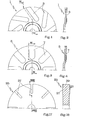
- Figs. 1 and 2 show disk-shaped grinding wheels having a depressed center 1, in which the projections 3 are made on the front surface of the grinding wheel at angles in a direction opposite to the direction of rotation of the grinding wheel.
- active surfaces in the present case both the front surface and the edge defined by said front surface and the peripheral surface are to be understood.
- Figs. 3 and 4 likewise show disk-shaped grinding wheels having a depressed center 5, which, as is known, are used by the corner or edge by generally manual tools; in said type of grinding wheel, the projections are radial and also in this case are located on the front surface and the peripheral surface.
- Figs. 5 and 6 show disk-shaped grinding wheels having a plurality of incisions or openings both on the front and peripheral surfaces to increase the efficiency of the grinding wheel; said cavities may be of various nature according to the type of grinding wheel to be produced and- the work to be carried out.
- the openings are formed by through slots 9 made on the peripheral edge 11 and the face 13 of the grinding wheel and arranged along radii of circles at an appropriate pitch, these radii being angularly offset relative to one another at a suitable angle.
- the pitch of the slots along said radii is the same in all of said radii, but their location is offset from one radiu s to an adjacent one so as to create the so-called “renewable toothing" which consists in that, when a series of slots, for example the outer ones, are worn out, the slots arranged on the circumference immediately therebelow are being prepared for this purpose.
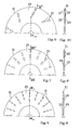
- the slots 17 are provided at an angle relative to the radius at an appropriate negative angle relative to the direction of rotation of the grinding wheel.
- the slots 17 are opposed on both faces 13.
- the cavities provided on the faces 13 of the grinding wheel substantially are straight grooves 19 which are negatively inclined relative to the direction of rotation of the grinding wheel.
- Fig. 15 shows another embodiment of a disk-shaped grinding wheel according to the invention and more particularly a disk-shaped grinding wheel in which the openings 23 are opposed; said removals are effected on either face of the grinding wheel in alternate relation so as to provide a grinding wheel having a zigzag cutting profile. Said profile is shown in Fig. 16.
- the thickness of the grinding wheel is smaller than the thickness of the grinding wheel of which it was made, but said zigzag shape increases the active surface of the grinding wheel due to the inclination of the walls and said inclination increases the efficiency thereof by thrust action.
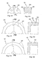
- Figs. 17 and 18 show a flat disk-shaped grinding wheel 25 on the front surfaces of which the projections 27 are provided.
- Said projections 27 are provided on both sides of the present grinding wheel 25 and by "active surfaces” obviously both the front surfaces and the edge defined by said front surfaces and the peripheral cylindrical surface 29 are to be understood.
- wear of the grinding wheel means wear of the peripheral surface 29 and of the front surfaces extending normally thereto; the "renewable toothing" presents itself suitable for the purpose as said active surface or said active surfaces wear out.
- Figs. 19 and 20 show a disk-shaped cylindrical grinding wheel 31 analogous to the grinding wheel shown in Figs. 17 and 18, but of greater diameter; said grinding wheel is likewise provided with appropriate projections 32 on the plane faces normal to the cylindrical surface; said projections and the cylindrical surface 33 constitute the "active edge” so that when the grinding wheel works in the cylindrical sense, i.e. with the cylindrical surface 33, the projections 32 constitute the "renewable toothing" of said grinding wheel as it wears out.
- the working surface is not only the plane surface 49, but often also involves the edge, so that said edge also forms part of the active surface of the grinding wheel and the projections provided on said outer wall constitute the "renewable toothing" mentioned previously.
- Figs. 27 and 28 show a cylindrical double cup-shaped grinding wheel 51 in which the projections 53 are provided on both cups on the outer cylindrical wall of the cup 51.
- Figs. 29 and 30 show an annular grinding wheel 55 on which the projections 57 are provided on the cylindrical surface thereof, the "active edge" and the renewable toothing being thus constituted by the plane surface 59 and the projection 57 normal thereto.
- Figs. 31 and 32 show a segment 61 of a segmental grinding wheel in which the projections 63 are provided in the direction indicated in the F.igure, the length of said projections being limited to permit easier gripping of the segment by the mechanical fixing members.
- Figs. 33 and 34 show another type of segment 65 of a segmental grinding wheel wherein there are provided projections'67 having a plane top, or cavities ' 69 provided on the outer cylindrical surface.
- the projections provided on the abrasive surfaces of said grinding wheels herein described are in the form of cylindrical, oval, prismatic, rectangular, triangular and the like protuberances, i.e. each type of said protuberances may have the cross section of a regular or irregular plane geometric figure.
Abstract
Normal grinding wheels which may be cylindrical; provided with a simple and double recess, in disk shape, in simple and double, cylindrical and conical cup-shape, with a depressed center, annular, segmental, etc., have on their abrasive surface a plurality of projections and /or recesses of the rib and/or cavity type, of various shapes, distributed on said abrasive surfaces radially or at appropriate angles according to the type of grinding wheel and the purpose thereof; said plurality of projections and/or recesses, ribs and/or cavities, as the case may be, constituting a "renewable toothing" over the entire length of the useful portion of the grinding wheel until it is worn out.
Description
- The present invention relates to grinding wheels with renewable toothing.
- It is known that the present grinding wheels used in industry have substantially smooth working surfaces irrespective of whether the grinding wheels are cylindrical, cup-shaped, disk-shaped, ring-shaped, segmental and so on.
- It is likewise known that some of said grinding wheels, especially those of considerable dimensions and mounted on machine tools, have holes made therein for requirements of aeration and/or cooling and/or lubrication.
- Other grinding wheels of the disk type, mounted on portable machine tools or simple equipment, cannot have holes because of their very nature and are used as they are, with a smooth surface.
- The essential problem in grinding wheels is that of keeping their active surface efficient as long as possible, which, where possible, is regularly effected by dressing by means of a diamond point.
- Said dressing of the abrasive grain by means of a diamond point wears the grinding wheel and above all causes said grinding wheel to have on the surface of the workpiece abrasive surfaces that are anything but homogeneous, namely with a sharp grain immediately after the passage of the diamond and a blunt grain at the end of the operation.
- Said case obviously does not occur in disk grinding wheels where due to the nature of the grinding wheels, the type of the machine tools on which they are mounted, they substantially work with a high degree of removal of material until they are worn out.
- This leads to problems of clogging, of heating of the workpiece, of rapid wearing out of the abrasive grain, causing in said grinding wheels an efficiency of production which is not always satisfactory.
- It is an object of the present invention to at least partly eliminate this inconvenience by providing the grinding wheels with means for maintaining a sharp grain for a longer time and simultaneously provide automatic means for renewing the grain, which permits a longer life of the grinding wheels together with a greater and longer lasting efficiency, i.e. a greater productivity.
- The fundamental feature of the present invention consists in that normal grinding wheels, which may be cylindrical, provided with a simple and double recess, in disk shape, in simple and double, cylindrical and conical cup shape, with a depressed center, annular, segmental etc., have on their abrasive surface a plurality of projections and/or recesses of the rib and/or cavity type, of various shape, distributed on said abrasive surfaces radially or at appropriate angles according to the type of grinding wheel and the purpose thereof; said plurality of projections and/ or recesses, ribs and/or cavities, as the case may be, constituting a "renewable toothing" over the entire length' of the useful portion of the grinding wheel until it is worn out.
- According to a particular feature of the present invention, the present grinding wheels are disk-shaped with a depressed center, of the cutting and/or deburring type, for tangential or round grinding, characterized in that said grinding wheels have on their active surface a plurality of projections of the rib or toothing type, having an inclination opposed to the direction of rotation of the disk-shaped grinding wheel, arranged along angularly spaced radii so as to constitute a "renewable toothing" in the sense that, starting from the outside, as the diameter diminishes due to wear of the disk, always new toothings suitable for the purpose are formed, which toothings in fact are formed by said ribs, and so on until the useful portion of the tool is completely worn out.
- According to a variation of the feature mentioned above, the disk-shaped grinding wheels with depressed center, of the cutting and/or deburring type, for tangential and round grinding, are characterized in that they have on their active surface a plurality of projections of the rib or toothing type, arranged radially and angularly spaced so as to constitute a "renewable toothing" analogous to the one described in the preceding feature and efficient until the useful portion of the grinding wheel is completely worn out.
- According to a further fundamental feature of the present invention, the disk-shaped grinding wheels of the cutting and/or deburring type, for tangential and round grinding, have on their active surface a plurality of recesses of various shapes, of the through type or not, distributed on said active surfaces on different arcs of radii appropriately spaced along said arcs of circle and spaced along the radii of said arcs; said recesses being provided with appropriate angles relative to the center of the grinding wheel, of appropriate pitch along said radii, of appropriate width and frequency along said arcs of circle, according to the type of disk-shaped grinding wheel to be produced; said appropriately arranged recesses or slots constituting a "renewable toothing" in the sense that when a series of slots along a circumference of a given radius has come to an end, another series is automatically formed along another circumference of smaller radius and so on until the grinding wheel is worn out.
- According to a variation of the feature mentioned above, the present disk-shaped grinding wheels are disk-shaped grinding wheels whose recesses are constituted by substantially rectangular slots arranged to extend through the entire active surface of the grinding wheel along angularly spaced radii and spaced along said radii from the center to the periphery and offset relative to one another in said radii so as to constitute a "renewable toothing" in the sense that, as mentioned before, once the slots appertaining to the first outer circle have come to an end or are about to come to an end because of wear of the disk, the slots adapted for the purpose and appertaining to the second circle present themselves by coming to the outside, and so on, until the disk is worn out; said alternation of slots ready for use on the active surface of the disk constituting the so-called "renewable toothing" as mentioned above.
- According to another variation of the present invention, the present grinding wheels are disk-shaped grinding wheels whose recesses are constituted by substantially rectangular slots that are no through slots but arranged in alternate or opposed fashion on both faces of the grinding wheels, again according to different arcs of circle on radii offset at different angles relative to one another on the active surface of the disk; the "renewable toothing" being thus formed both among the slots of one face and the slots of the opposed face.
- According to another fundamental feature of the present invention, the present disk-shaped grinding'wheels have on their active surface, instead of slots that are through slots or not, a plurality of grooves that are no through grooves and are arranged in opposed or alternate fashion on both faces bf said active surface and have an inclination and, if desired, curvature from the center to the periphery of the disk, opposed to the direction of rotation of the disk; the "renewable toothing" being formed in this embodiment, as in the others in which the active surface is substantially frontal, by the continuous renewal of the profile of the grooves in the sense that the worn portion of said groove is replaced by a new portion thereof until the grinding wheel is worn out.
- A further feature of the present invention consists in that the present grinding wheels are .disk-shaped grinding wheels of the type for cylindrical external grinding, cylindrical internal grinding, tangential grinding, characterized in that said grinding wheels are substantially disk-shaped grinding wheels carrying on both parallel and opposed plane faces a plurality of projections of the rib or toothing type, arranged in alternate or opposed fashion on both faces of the plane abrasive surface radially or at a negative angular inclination relative to the direction of rotation of the disk, said projections being angularly spaced and of appropriate length substantially corresponding to the useful area of the grinding wheel so as to constitute a "renewable toothing" over the entire length of the useful portion of the tool.
- A further fundamental feature of the present invention consists in that the present grinding wheels are cup-shaped grinding wheels having a simple and/or double, cylindrical and/or conical cup, characterized in that said grinding wheels carry on the abrasive surface of their jacket a plurality of projections of the rib type, arranged normal or at an angle to the surface to be ground, appropriately spaced from one another, arranged in opposed or alternating fashion on the two walls of the cup, said projections having a length corresponding to the useful length of the grinding wheel so as to constitute a "renewable toothing" effective over the entire useful length of the grinding wheel.
- According to a variation of the preceding feature, the cup-shaped-grinding wheels having a simple or double, cylindrical and/or conical cup are characterized in that they have on one of their (inner or outer) surfaces of the jacket a plurality of rib type projections that are normal or inclined relative to the surface to be ground, as in the preceding feature, so as to constitute a "renewable toothing" only on one, inner or outer, wall of the jacket of the cup, which is effective over the entire length of the useful portion of the grinding wheel.
- A further fundamental feature of the present invention consists in that the present grinding wheels are segmental grinding wheels, particularly with front segments of the externally and internally radiated, laterally locking type, characterized in that said segmental grinding wheels have on the surface of their jacket a plurality of projections and/or recesses of the rib and/or cavity type, arranged normally or at an angle to the surface to be ground, and appropriately spaced from one another, said projections being of appropriate length relative to the height of the jacket or useful height of the grinding wheel so as to form a "renewable toothing" which is effective over the entire length of the useful portion of the jacket.
- A further fundamental feature of the present invention consists in that the projections and/or recesses of the rib and/or cavity type, which may be through cavities or not, mentioned in all the preceding types of grinding wheels, whether they are disk-shaped, with a depressed center, cup-shaped, cylindrical, frontal, segmental and the like, have a cross section which is thought most appropriate for each case, said cross sections therefore being semicircular, oval, in the form of an arc of a circle, prismatic, rectangular, triangular, etc., each of said types of cross sections reflecting a regular or irregular plane geometrical figure.
- The essential advantages of the "renewable toothing" provided in said grinding wheels consist in that:
- - with the same type of abrasive, hardness, binder, structure, etc., by an "appropriate form" of the projection and/or recess one obtains a greater penetration of the tool into the material and thus a considerable increase of productivity;
- - these surface interruptions or "toothings", whether they are positive or negative, enable the tool to discharge the chips that it produces and by promoting spontaneous regeneration of the active surface render the tool less prone to clogging;
- - the "renewable toothing" constitutes the mechanical equivalent of an increase of the active surface of the grinding wheel, which active surface further is continuously renewed.
- The invention will now be described in detail with particular reference to the accompanying drawings furnished by way of a non-limiting example and in which:
-
- - Fig. 1 is a partial front view of a disk-shaped grinding wheel having'a depressed center and projections offset at an angle in a direction opposite to the direction of rotation of the grinding wheel;
- - Fig. 2 is a transverse section of Fig. 1, taken along the line II-II;
- - Fig. 3 is a partial front view of a grinding wheel having a depressed center and projections arranged radially;
- - Fig. 4 is a transverse section of Fig. 3, taken along the line IV-IV;
- - Fig. 5 is a partial front view of a disk-shaped grinding wheel with radiant through slots;
- - Fig. 6 is a cross section of Fig. 5, taken along the line VI-VI;
- - Fig. 7 is a partial front view of a disk-shaped grinding wheel with radial slots that are no through slots and arranged alternately on both faces of the disk;
- - Fig. 8 is a cross section of Fig. 7, taken along the line VIII-VIII;
- - Fig. 9 is a partial front view of a disk-shaped grinding wheel with opposed slots that are no through slots and inclined negatively;
- - Fig. 10 is a cross section of Fig. 9, taken along the line X-X;
- - Fig. 11 is a partial front view of a disk-shaped grinding wheel with negatively inclined rectilinear grooves;
- - Fig. 12 is a cross section of Fig. 11, taken along the line XII-XII and showing the opposed grooves;
- - Fig. 12a is a cross section analogous to Fig. 12, in which the grooves are not opposed but alternately offset on both faces;
- - Fig. 13 is a partial front view of a disk-shaped grinding wheel with curved grooves;
- - Fig. 14 is a cross section of Fig. 13, taken along the line XIV-XIV and showing opposed grooves;
- - Fig. 14a is a cross section analogous to Fig. 14, in which the grooves are alternately offset on both faces;
- - Fig. 15 is a partial front view of a disk-shaped grinding wheel in which the openings are formed by alternate removals on both faces, producing a sinusoidal profile;
- - Fig. 16 is a partial side view of Fig. 15;
- - Fig. 17 is a partial front view of a disk-shaped grinding wheel with projections arranged radially on both faces;
- - Fig. 18 is a cross section of Fig. 17, taken along the line XVIII-XVIII;
- - Fig. 19 is a partial front view of a cylindrical grinding wheel with projections arranged on both plane faces;
- - Fig. 20 is a cross section of Fig. 19, taken along the line XX-XX;
- Fig. 21 is a partial front view of a cylindrical cup-shaped grinding wheel with opposed projections on both walls of the cup;
- - Fig. 22 is a cross section of Fig. 21, taken along the line XXII-XXII;
- - Fig. 23 is a partial front view of a cylindrical cup-shaped grinding wheel with projections arranged on on the outer wall of the cup or jacket;
- Fig. 24 is a cross section of Fig. 23, taken along the line XXIV-XXIV;
- - Fig. 25 is a partial front view of a conical cup-shaped grinding wheel with projections arranged on the outer wall of the jacket;
- - Fig. 26 is a cross section of Fig. 25, taken along the line XXVI-XXVI;
- - Fig. 27 is a partial front view of a cylindrical double cup-shaped grinding wheel with projections arranged on the outer surface;
- - Fig. 28 is a cross section of Fig. 27, taken along the line XXVIII-XXVIII;
- - Fig. 29 is a partial front view of a cylindrical annular grinding wheel with projections arranged along the outer generatrices of the cylinder;
- - Fig. 30 is a cross section of Fig. 29, taken along the line XXX-XXX;
- - Fig. 31 is a partial front view of a segment of a segmental grinding wheel according to the invention;
- - Fig. 32 is a cross section of Fig. 31, taken along the line XXXII-XXXII;
- - Fig. 33 is a partial front view of another embodiment of a segmental grinding wheel according to the invention;
- - Fig. 34 is a cross section of Fig. 33, taken along the line XXXIV-XXXIV.
- As mentioned before, Figs. 1 and 2 show disk-shaped grinding wheels having a
depressed center 1, in which theprojections 3 are made on the front surface of the grinding wheel at angles in a direction opposite to the direction of rotation of the grinding wheel. - By the term "active surfaces" in the present case both the front surface and the edge defined by said front surface and the peripheral surface are to be understood.
- Figs. 3 and 4 likewise show disk-shaped grinding wheels having a
depressed center 5, which, as is known, are used by the corner or edge by generally manual tools; in said type of grinding wheel, the projections are radial and also in this case are located on the front surface and the peripheral surface. - Figs. 5 and 6 show disk-shaped grinding wheels having a plurality of incisions or openings both on the front and peripheral surfaces to increase the efficiency of the grinding wheel; said cavities may be of various nature according to the type of grinding wheel to be produced and- the work to be carried out.
- In Figs. 5 and 6 the openings are formed by through slots 9 made on the
peripheral edge 11 and theface 13 of the grinding wheel and arranged along radii of circles at an appropriate pitch, these radii being angularly offset relative to one another at a suitable angle. - As is apparent, the pitch of the slots along said radii is the same in all of said radii, but their location is offset from one radiusto an adjacent one so as to create the so-called "renewable toothing" which consists in that, when a series of slots, for example the outer ones, are worn out, the slots arranged on the circumference immediately therebelow are being prepared for this purpose.
- In Fig. 7 said
slots 15 are no "through" slots, but placed in alternate relation according to the same criteria on both faces 13. - In Fig. 9 the
slots 17 are provided at an angle relative to the radius at an appropriate negative angle relative to the direction of rotation of the grinding wheel. In this example theslots 17 are opposed on both faces 13. - In Fig. 11 the cavities provided on the
faces 13 of the grinding wheel substantially arestraight grooves 19 which are negatively inclined relative to the direction of rotation of the grinding wheel. - Fig. 12 shows a cross section of Fig. 11 with
opposed grooves 19; in Fig. 12a saidgrooves 19 alternate on both faces 13. - Fig. 13 shows a further embodiment of the present invention in which the
grooves 21 are curved again at a negative angle relative to the direction of rotation. - Figs. 14 and 14a show the
grooves 21 opposed and alternating, respectively, on bothfaces 13 of the grinding wheel. - In the embodiments comprising grooves it is particularly evident that the "renewable toothing" is not formed, as in the previous cases, by the replacement of a new series of openings or slots ready for use when a series placed outwardly thereof is worn out,.but by the continuous renewal of the active profile in the sense that the worn portion of a groove is automatically replaced by a new portion of the same groove.
- In addition to the case of disk-shaped grinding wheels with grooves this obviously also happens in disk-shaped grinding wheels with peripheral frontal action, in which the "renewable toothing" of the second type overlaps the (essentially peripheral) "renewable toothing" of the first type.
- However, it goes without saying that one does not exclude the other and that the concepts of either "toothing" are much more closely related and similar than it might appear at first sight.
- Fig. 15 shows another embodiment of a disk-shaped grinding wheel according to the invention and more particularly a disk-shaped grinding wheel in which the
openings 23 are opposed; said removals are effected on either face of the grinding wheel in alternate relation so as to provide a grinding wheel having a zigzag cutting profile. Said profile is shown in Fig. 16. - In this embodiment the thickness of the grinding wheel is smaller than the thickness of the grinding wheel of which it was made, but said zigzag shape increases the active surface of the grinding wheel due to the inclination of the walls and said inclination increases the efficiency thereof by thrust action.
- Figs. 17 and 18 show a flat disk-shaped
grinding wheel 25 on the front surfaces of which theprojections 27 are provided. Saidprojections 27 are provided on both sides of thepresent grinding wheel 25 and by "active surfaces" obviously both the front surfaces and the edge defined by said front surfaces and the peripheralcylindrical surface 29 are to be understood. Also in this case, as in the preceding cases, wear of the grinding wheel means wear of theperipheral surface 29 and of the front surfaces extending normally thereto; the "renewable toothing" presents itself suitable for the purpose as said active surface or said active surfaces wear out. - Figs. 19 and 20 show a disk-shaped
cylindrical grinding wheel 31 analogous to the grinding wheel shown in Figs. 17 and 18, but of greater diameter; said grinding wheel is likewise provided withappropriate projections 32 on the plane faces normal to the cylindrical surface; said projections and thecylindrical surface 33 constitute the "active edge" so that when the grinding wheel works in the cylindrical sense, i.e. with thecylindrical surface 33, theprojections 32 constitute the "renewable toothing" of said grinding wheel as it wears out. - Figs. 21 and 22, on the other hand, show a cup-shaped
grinding wheel 35 whereinappropriate projections 37 are provided on both opposite sides of thecylindrical wall 36 normal to thesurface 39 and constitute the "renewable toothing" of the present grinding wheel. - Figs. 23 and 24 likewise show a cylindrical cup-shaped
grinding wheel 41 analogous to the grinding wheel shown in Figs. 21 and 22, but with theprojections 42 provided only on the outer jacket of the grinding wheel. - Figs. 25'and 26 constitute an example of a conical cup-shaped
grinding wheel 43 on theouter wall 45 of whichappropriate projections 47 are provided which in this case are oblique to the plane normal to the axis of the grinding wheel, said plane abrasive surface and the cross section of the projection constituting the "renewable toothing" thereof as said grinding wheel wears out. - It is pointed out again that the working surface is not only the
plane surface 49, but often also involves the edge, so that said edge also forms part of the active surface of the grinding wheel and the projections provided on said outer wall constitute the "renewable toothing" mentioned previously. - Figs. 27 and 28 show a cylindrical double cup-shaped
grinding wheel 51 in which theprojections 53 are provided on both cups on the outer cylindrical wall of thecup 51. - Figs. 29 and 30 show an
annular grinding wheel 55 on which theprojections 57 are provided on the cylindrical surface thereof, the "active edge" and the renewable toothing being thus constituted by theplane surface 59 and theprojection 57 normal thereto. - Figs. 31 and 32 show a
segment 61 of a segmental grinding wheel in which theprojections 63 are provided in the direction indicated in the F.igure, the length of said projections being limited to permit easier gripping of the segment by the mechanical fixing members. - Figs. 33 and 34 show another type of
segment 65 of a segmental grinding wheel wherein there are provided projections'67 having a plane top, orcavities '69 provided on the outer cylindrical surface. - As previously mentioned, it is to be understood that the projections provided on the abrasive surfaces of said grinding wheels herein described, whether they be disk-shaped, having a depressed center, cup-shaped with a double or simple cup, cylindrical and conical and so on, are in the form of cylindrical, oval, prismatic, rectangular, triangular and the like protuberances, i.e. each type of said protuberances may have the cross section of a regular or irregular plane geometric figure.
- Evidently the invention is not limited to the described and illustrated embodiment and numerous variations and further improvements may be made therein without departing from the scope of the invention.
Claims (13)
1. Grinding wheels with renewable toothing, characterized in that normal grinding wheels, which may be cylindrical, provided with a simple and double recess, in disk shape, in simple and double, cylindrical and conical cup shape, with a depressed center, annular, segmental, etc., have on their abrasive surface a plurality of projections and/or recesses of the rib and/or cavity type, of various shape, distributed on said abrasive surfaces radially or at appropriate angles according to the type of grinding wheel and the purpose thereof; said plurality of projections and/or recesses, ribs and/or cavities, as the case may be, constituting a "renewable toothing" over the entire length of the useful portion of the grinding wheel until it is worn out.
2. Grinding wheels with renewable toothing, which are disk-shaped, with a depressed center and may be of the deburring type, for tangential or round grinding, according to claim 1. characterized in that said grinding wheels have on their active surface a plurality of projections of the rib or toothing type, having an inclination opposed to the direction of rotation of the disk-shaped grinding wheel, arranged along angularly spaced radii so as to constitute a "renewable toothing" in the sense that, starting from the outside, as the diameter diminishes due to wear of the disk, always new toothing sections suitable for the purpose are formed and so on until the useful portion of the tool is completely worn out.
3. Grinding wheels with renewable toothing, which are disk-shaped with a depressed center and may be of the deburring type, for tangential and round grinding, according to claim 1 and a variation of claim 2, characterized in that they have on their active surface a plurality of projections of the rib or toothing type, arranged radially and angularly spaced so as to constitute a "renewable toothing" analogous to the one described in the preceding feature and efficient until the useful portion of the grinding wheel is completely worn out.
4. Grinding wheels with renewable toothing, which are disk-shaped of the type for cutting and/or deburring, for tangential and round grinding, according to claim 1, characterized in that said grinding wheels have on their active surface a plurality of recesses of various shapes, of the through type or not, distributed on said active surfaces on different arcs of radii appropriately spaced along said arcs of circle and spaced along the radii of arcs; said recesses being provided with appropriate angles relative to the center of the grinding wheel, of appropriate pitch along said radii, of appropriate width and frequency along said arcs of circle, according to the type of disk-shaped grinding wheel to be produced; said appropriately arranged recesses or slots constituting a "renewable toothing" in the sense that when a series of slots along a circumference of a given radius has come to an end, another series is automatically formed along another circumference of smaller radius and so on until the grinding wheel is worn out.
5. Grinding wheels with renewable toothing, which are disk-shaped of the type for cutting and/or deburring, for tangential and round grinding, according to claim 1 and a variation of claim 4, characterized in that said grinding wheels are disk-shaped grinding wheels whose recesses are constituted by substantially-rectangular slots arranged to extend through the entire active surface of the grinding wheel along angularly spaced radii and spaced along said radii from the center to the periphery and offset relative to one another in said radii so as to constitute a "renewable toothing" in the sense that, as mentioned before, once the slots appertaining to the first outer circle have come to an end or are about to come to an end because of wear of the disk, the slots adapted for the purpose and appertaining to the second circle present themselves by coming to the outside, and so on, until the disk is worn out; said alternation of slots ready for use on the active surface of the disk constituting the so-called "renewable toothing" as mentioned above.
6. Grinding wheels with renewable toothing, which are disk-shaped of the type for cutting and/or deburring, for tangential and round grinding, according to claim 1 and a further variation of claim 4, characterized in that the present grinding wheels are disk-shaped grinding wheels whose recesses are constituted by substantially rectangular slots that are no through slots but arranged in alternative or opposed fashion on both faces of the grinding wheels, again according to different arcs of circle on radii offset at different angles relative to one another on the active surface of the disk; the"renewable toothing" being thus formed both among the slots of one face and the slots of the opposed face.
7. Grinding wheels with renewable toothing, which are disk-shaped of the type for cutting and/or deburring, for tangential and round grinding, according to claim 1 and a further variation of claim 4, characterized in that the present disk-shaped grinding wheels have on their active surface, instead of slots that are through slots or not, a plurality of grooves that are no through grooves and are arranged in opposed or alternate fashion on both faces of said active surface and have an inclination and, if desired, curvature from the center to the periphery of the disk, opposed to the direction of rotation of the disk; the "renewable toothing" being formed in this embodiment, as in the others in which the active surface is substantially frontal, by the continuous renewal of the profile of the grooves in the sense that the worn portion of said groove is replaced by a new portion thereof until the grinding wheel is worn out.
8. Grinding wheels with renewable toothing, which are disk-shaped grinding wheels of the type for cylindrical external grinding, cylindrical internal grinding, tangential grinding, characterized in that said grinding wheels are substantially disk-shaped grinding wheels carrying on both parallel and opposed faces a plurality of projections of the rib or toothing type, arranged in alternate or opposed fashion on both faces of the plane abrasive surface radially or at a negative angular inclination relative to the direction of rotation of the disk, said projections being angularly spaced and of appropriate length substantially corresponding to the useful area of the grinding wheel so as to constitute a "renewable toothing" over the entire length of the useful portion of the tool.
9. Grinding wheels with renewable toothing, which are cup-shaped grinding wheels having a simple and/or double, cylindrical and/or conical cup, characterized in that said grinding wheels carry on the abrasive surface of their jacket a plurality of projections of the rib type, arranged normal or at an angle to the surface to be ground, appropriately spaced from one another, arranged in opposed or alternating fashion on the two walls of the cup; said projections having a length corresponding to the useful length of the grinding wheel so as to constitute a "renewable toothing" effective over the entire useful length of the grinding wheel.
10. Grinding wheels with renewable toothing, which are cup-shaped grinding wheels, according to the preceding claims-and a variation of claim 9, characterized in that they have on one of their (inner or outer) surfaces of the jacket a plurality of projections of the rib or toothing type that are normal or inclined relative to the surface to be ground, as in the preceding feature, so as to constitute a "renewable toothing" only on one, inner or outer, wall of the jacket of the cup, which is effective over the entire length of the useful portion of the grinding wheel.
11. Grinding wheels with renewable toothing, which are segmental grinding wheels, particularly with front segments of the externally and internally radiated, laterally locking type,according to the preceding claims, characterized in that said segmental, particularly frontal, grinding wheels have on the surface of their jacket a plurality of projections of the rib or toothing type, arranged normally or at an angle to the surface to be ground, and appropriately spaced from one another, said projections being of appropriate length relative to the height of the jacket or useful height of the grinding wheel so as to form a "renewable toothing" which is effective over the entire length of the useful portion of the jacket.
12. Grinding wheels with renewable toothing according to each of the preceding claims, characterized in that the projections and recesses are provided in opposed relation on both faces of the active surface of the grinding wheel, said alternation of projections and recesses providing a sinusoidal cutting profile.
13. Grinding wheels with renewable toothing according to each of the preceding claims, characterized in that the projections and/or recesses of the rib type and/or cavities, that may be through cavities or not, mentioned in all the preceding types of grinding wheels, whether they are disk-shaped, with a depressed center, cup-shaped, frontal, segmental and the like, have a cross section which is thought most appropriate for each case, said cross sections therefore being semicircumar, oval, in the form of an arc of a circle, prismatic, rectangular, etc., each of said types of cross sections reflecting a regular or irregular plane geometrical figure.
Applications Claiming Priority (2)
| Application Number | Priority Date | Filing Date | Title |
|---|---|---|---|
| IT6813583 | 1983-10-31 | ||
| IT68135/83A IT1162977B (en) | 1983-10-31 | 1983-10-31 | RENEWABLE ABRASIVE WHEELS |
Publications (1)
| Publication Number | Publication Date |
|---|---|
| EP0144468A1 true EP0144468A1 (en) | 1985-06-19 |
Family
ID=11308086
Family Applications (1)
| Application Number | Title | Priority Date | Filing Date |
|---|---|---|---|
| EP83201716A Withdrawn EP0144468A1 (en) | 1983-10-31 | 1983-12-05 | Grinding wheels with renewable toothing |
Country Status (2)
| Country | Link |
|---|---|
| EP (1) | EP0144468A1 (en) |
| IT (1) | IT1162977B (en) |
Cited By (5)
| Publication number | Priority date | Publication date | Assignee | Title |
|---|---|---|---|---|
| EP0803334A2 (en) * | 1996-04-26 | 1997-10-29 | Indunorm Hydraulik GmbH | Rotary knife |
| US7195549B2 (en) | 2004-08-23 | 2007-03-27 | Saint-Gobain Abrasives, Inc. | Drum grinding wheel |
| CN105690282A (en) * | 2016-04-22 | 2016-06-22 | 丹阳市剑庐工具有限公司 | Annular tooth dividing grinding wheel and preparation process thereof |
| WO2020058788A1 (en) * | 2018-09-21 | 2020-03-26 | Aspi Sp. Z O.O. Sp. K. | Circular saw blade with a grooved body and method of making the same |
| US11612946B2 (en) * | 2020-02-12 | 2023-03-28 | Baron Investments, Llc | Blade assembly with ventilation openings |
Families Citing this family (1)
| Publication number | Priority date | Publication date | Assignee | Title |
|---|---|---|---|---|
| CN108000344A (en) * | 2017-12-06 | 2018-05-08 | 浙江工业大学 | Polishing roller for the parabola shaped groove of band for the pressure burnishing device that linearly surges |
Citations (4)
| Publication number | Priority date | Publication date | Assignee | Title |
|---|---|---|---|---|
| FR963496A (en) * | 1950-07-11 | |||
| US2755601A (en) * | 1953-09-30 | 1956-07-24 | Lux Hans Gunther | Grinding apparatus |
| US3657845A (en) * | 1969-06-14 | 1972-04-25 | Shinji Sekiya | Resinoid pocketed cutoff and grinding wheel and method of making same |
| GB1511346A (en) * | 1974-05-28 | 1978-05-17 | Engelhard Min & Chem | Abrasive tool for grindling and polishing purposes |
-
1983
- 1983-10-31 IT IT68135/83A patent/IT1162977B/en active
- 1983-12-05 EP EP83201716A patent/EP0144468A1/en not_active Withdrawn
Patent Citations (4)
| Publication number | Priority date | Publication date | Assignee | Title |
|---|---|---|---|---|
| FR963496A (en) * | 1950-07-11 | |||
| US2755601A (en) * | 1953-09-30 | 1956-07-24 | Lux Hans Gunther | Grinding apparatus |
| US3657845A (en) * | 1969-06-14 | 1972-04-25 | Shinji Sekiya | Resinoid pocketed cutoff and grinding wheel and method of making same |
| GB1511346A (en) * | 1974-05-28 | 1978-05-17 | Engelhard Min & Chem | Abrasive tool for grindling and polishing purposes |
Cited By (7)
| Publication number | Priority date | Publication date | Assignee | Title |
|---|---|---|---|---|
| EP0803334A2 (en) * | 1996-04-26 | 1997-10-29 | Indunorm Hydraulik GmbH | Rotary knife |
| EP0803334A3 (en) * | 1996-04-26 | 1998-06-10 | Indunorm Hydraulik GmbH | Rotary knife |
| US7195549B2 (en) | 2004-08-23 | 2007-03-27 | Saint-Gobain Abrasives, Inc. | Drum grinding wheel |
| CN105690282A (en) * | 2016-04-22 | 2016-06-22 | 丹阳市剑庐工具有限公司 | Annular tooth dividing grinding wheel and preparation process thereof |
| CN105690282B (en) * | 2016-04-22 | 2018-11-02 | 丹阳市剑庐工具有限公司 | A kind of annular divides tooth emery wheel and its preparation process |
| WO2020058788A1 (en) * | 2018-09-21 | 2020-03-26 | Aspi Sp. Z O.O. Sp. K. | Circular saw blade with a grooved body and method of making the same |
| US11612946B2 (en) * | 2020-02-12 | 2023-03-28 | Baron Investments, Llc | Blade assembly with ventilation openings |
Also Published As
| Publication number | Publication date |
|---|---|
| IT1162977B (en) | 1987-04-01 |
| IT8368135A0 (en) | 1983-10-31 |
Similar Documents
| Publication | Publication Date | Title |
|---|---|---|
| KR101544334B1 (en) | Double-sided cutting insert for milling | |
| KR100279184B1 (en) | Glass cutting disc | |
| US4767245A (en) | Annular hole cutter | |
| EP0008159B1 (en) | Cutting tool and insert for same | |
| KR100287610B1 (en) | Grinding tools with disc support | |
| KR970006958B1 (en) | Annular cutter having radial clearance | |
| US4729169A (en) | Inner rotary cutters for electric shavers and manufacturing processes for the same | |
| JPH09502397A (en) | Cutting tip | |
| US6551181B2 (en) | Abrasive wheel | |
| US5496209A (en) | Blade grinding wheel | |
| US5647698A (en) | Tire rasp blade | |
| EP0144468A1 (en) | Grinding wheels with renewable toothing | |
| CA1227931A (en) | Abrasive cutting wheel | |
| JPH01153209A (en) | Cutting insert and usage thereof | |
| US3079669A (en) | Aluminum removing wheel | |
| US6368107B2 (en) | Dental tool | |
| JPH0379129B2 (en) | ||
| US5453041A (en) | Cutting edge teeth and their orientation on tools used to shape and texture the surfaces of non-metallic and composite materials | |
| JPS6279962A (en) | Method and tool for molding and dressing rubstone for cutting male screw | |
| US6062969A (en) | Grinding wheel with spiral grooved face | |
| US5024026A (en) | Segmental grinding wheel | |
| EP0404298A1 (en) | End mill for finishing the face or side of hard work | |
| CN213469833U (en) | Double-layer tooth rotary file | |
| CA2077568A1 (en) | Grinding tool | |
| SU1215971A1 (en) | Grinding wheel |
Legal Events
| Date | Code | Title | Description |
|---|---|---|---|
| PUAI | Public reference made under article 153(3) epc to a published international application that has entered the european phase |
Free format text: ORIGINAL CODE: 0009012 |
|
| AK | Designated contracting states |
Designated state(s): AT BE CH DE FR GB LI LU NL SE |
|
| XX | Miscellaneous (additional remarks) |
Free format text: WEITERE PRIORITAET: 25.11.82 IT 6837282. DIE FRIST VON ARTIKEL 87(1)EPUE GILT GEMAESS REGEL 85(2)EPUE ALS GEWAHRT (SIEHE AUCH ABL 1/84,16). |
|
| 17P | Request for examination filed |
Effective date: 19851218 |
|
| 17Q | First examination report despatched |
Effective date: 19860827 |
|
| STAA | Information on the status of an ep patent application or granted ep patent |
Free format text: STATUS: THE APPLICATION HAS BEEN WITHDRAWN |
|
| 18W | Application withdrawn |
Withdrawal date: 19870506 |
|
| RIN1 | Information on inventor provided before grant (corrected) |
Inventor name: BRUNO, MARIO |