EP0144342B1 - Ore irradiator - Google Patents
Ore irradiator Download PDFInfo
- Publication number
- EP0144342B1 EP0144342B1 EP84901606A EP84901606A EP0144342B1 EP 0144342 B1 EP0144342 B1 EP 0144342B1 EP 84901606 A EP84901606 A EP 84901606A EP 84901606 A EP84901606 A EP 84901606A EP 0144342 B1 EP0144342 B1 EP 0144342B1
- Authority
- EP
- European Patent Office
- Prior art keywords
- ducts
- irradiator
- lumps
- ore
- source
- Prior art date
- Legal status (The legal status is an assumption and is not a legal conclusion. Google has not performed a legal analysis and makes no representation as to the accuracy of the status listed.)
- Expired
Links
Images
Classifications
-
- G—PHYSICS
- G01—MEASURING; TESTING
- G01N—INVESTIGATING OR ANALYSING MATERIALS BY DETERMINING THEIR CHEMICAL OR PHYSICAL PROPERTIES
- G01N23/00—Investigating or analysing materials by the use of wave or particle radiation, e.g. X-rays or neutrons, not covered by groups G01N3/00 – G01N17/00, G01N21/00 or G01N22/00
- G01N23/22—Investigating or analysing materials by the use of wave or particle radiation, e.g. X-rays or neutrons, not covered by groups G01N3/00 – G01N17/00, G01N21/00 or G01N22/00 by measuring secondary emission from the material
- G01N23/221—Investigating or analysing materials by the use of wave or particle radiation, e.g. X-rays or neutrons, not covered by groups G01N3/00 – G01N17/00, G01N21/00 or G01N22/00 by measuring secondary emission from the material by activation analysis
- G01N23/222—Investigating or analysing materials by the use of wave or particle radiation, e.g. X-rays or neutrons, not covered by groups G01N3/00 – G01N17/00, G01N21/00 or G01N22/00 by measuring secondary emission from the material by activation analysis using neutron activation analysis [NAA]
-
- G—PHYSICS
- G01—MEASURING; TESTING
- G01N—INVESTIGATING OR ANALYSING MATERIALS BY DETERMINING THEIR CHEMICAL OR PHYSICAL PROPERTIES
- G01N2223/00—Investigating materials by wave or particle radiation
- G01N2223/07—Investigating materials by wave or particle radiation secondary emission
- G01N2223/074—Investigating materials by wave or particle radiation secondary emission activation analysis
- G01N2223/0745—Investigating materials by wave or particle radiation secondary emission activation analysis neutron-gamma activation analysis
-
- G—PHYSICS
- G01—MEASURING; TESTING
- G01N—INVESTIGATING OR ANALYSING MATERIALS BY DETERMINING THEIR CHEMICAL OR PHYSICAL PROPERTIES
- G01N2223/00—Investigating materials by wave or particle radiation
- G01N2223/20—Sources of radiation
- G01N2223/204—Sources of radiation source created from radiated target
-
- G—PHYSICS
- G01—MEASURING; TESTING
- G01N—INVESTIGATING OR ANALYSING MATERIALS BY DETERMINING THEIR CHEMICAL OR PHYSICAL PROPERTIES
- G01N2223/00—Investigating materials by wave or particle radiation
- G01N2223/60—Specific applications or type of materials
- G01N2223/635—Specific applications or type of materials fluids, granulates
Definitions
- This invention relates to apparatus for detecting the presence of a selected substance in ores by neutron activation analysis, for example the gold content of gold-bearing ores.
- a practical gold ore sorting plant needs to be able to process several tonnes of ore an hour, and hence must use a rapid analytical technique.
- a suitable technique is neutron activation analysis using the reaction 197 Au (n, n'y) 197m Au to activate gold present in a lump of ore, the 197m Au nuclides so produced decaying with a half-life of about 7.8 seconds, with the emission of y-rays of energy 279 keV.
- British Patent Specifications Nos. 2055465A and 2 101 304A U.S. Patent No. 4 340 443, and U.S. Serial No. 383 686 filed 27 May 1982, respectively
- an irradiator as claimed in claim 1.
- each neutron source may comprise a target arranged to be bombarded by a high energy particle beam, the particle beams being incident on the targets in a direction parallel to the longitudinal axes of the ducts and provided by a common particle accelerator.
- ducts are desirably adjacent to and thereby irradiated by more than one neutron source, and these ducts may be of greater cross-sectional area than those ducts which are adjacent to only one neutron source.
- the number of ducts is six and the number of neutron sources three, and the longitudinal axes of the ducts may be located approximately at the vertices of an equilateral triangle and at the mid-points of the sides of the triangle.
- each neutron source comprises a lithium target arranged to be bombared by a beam of high energy protons so as to produce neutrons of energy between 0.5 and 3.0 MeV.
- a gold ore sorting apparatus comprises a rock crusher and classifier 2 to which mined ore is supplied, in which the ore is crushed into lumps and divided into two streams of lumps corresponding to mesh sizes of about 80 mm and 60 mm respectively, while lumps smaller than mesh size about 35 mm are rejected. Both streams of lumps are passed through an irradiator 4 to be described in more detail later, and then all the lumps are caused to pass a y-ray detector assembly 6 arranged to detect y-rays having an energy of 279 keV arising from the decay of 197m Au nuclides and so signifying the presence of gold in the lumps of ore.
- Each lump of ore is interrogated individually by the detector assembly 6 to establish whether its gold content lies above or below some predetermined concentration.
- the critical concentration is typically in the range 0.5 to 5 parts per million (ppm), and might for example be set at 1 ppm.
- Each lump of ore is then passed into a sorter 8 arranged by means of a cable 7 to respond to signals from the detector assembly 6, and to sort each lump of ore into one of two outlet streams depending on whether the gold concentration in the lump lies above or below the predetermined concentration.
- the crusher and classifier 2 and the sorter 8 may be of types well known in the art, while the detector assembly 6 may be as described more fully in the aforementioned specifications to which reference may be made, the crusher and classifier 2, the sorter 8 and the detector assembly 6 not being the subject of the invention.
- the irradiator 4 comprises a close-packed array of three outer tubular steel cyclinders 12 and three inner tubular steel cyclinders 14, with their longitudinal axes upright, the axes of the three outer cylinders 12 being at the corners of a notional equilateral triangle, and the axes of the three inner cylinders 14 being near the mid points of the sides of the triangle.
- Each of the inner cylinders 14 is of internal diameter 32 cm and each of the outer cylinders 12 is of internal diameter 26 cm.
- the outer cylinders 12 and the inner cylinders 14, although close packed, are not contiguous, and each is caused to rotate about its longitudinal axis in a clockwise sense by a drive from an electric motor (not shown).
- the outer cylinders 12 and the inner cylinders 14 adjacent thereto define between them three spaces 15 in which respective neutron sources 16 are situated in a horizontal plane at an intermediate position along the length of the outer cylinders 12 and the inner cylinders 14.
- Each neutron source 16 comprises a lithium target, at the end of a respective evacuated flight tube (not shown), the three flight tubes emerging via a beam splitter (not shown) from a single proton accelerator (not shown), and the end portion of each flight tube extending parallel to the axes of the cylinders 12, 14.
- Flight tubes, beam splitters and accelerators are well known in the art, and further details will not be given.
- the outer cylinders 12, the inner cylinders 14 and the neutron sources 16 are located within a cylindrical chamber 20 defined by a concrete radiation shield 22 which is sufficiently thick to be substantially impervious to y-rays and to neutrons and far enough away so as not to generate an intense field of interfering low energy neutrons.
- a typical distance is 100 cm.
- the streams of ore from the crusher and classifier'2 are passed through the outer cylinders 12 and the inner cylinders 14, the stream of larger lumps of ore being passed through the inner cylinders 14.
- the accelerator is energised to cause a beam of protons of energy 4.5 MeV to bombard each lithium target, the proton beam being moved around the surface of the target to avoid localized overheating.
- Fast neutrons of energy between about 0.5 MeV and 2.8 MeV are produced by the reaction 3 Li (p, n) 4 Be, and irradiate the lumps of ore in the adjacent outer cylinders 12 and inner cylinders 14.
- the neutron flux decreases with distance from the sources 16, hence to provide as uniform an irradiation of the ore lumps as possible the outer cylinders 12 and the inner cylinders 14 are rotated about their . respective longitudinal axes so that each lump of ore traverses the high intensity region of the neutron flux from one of the sources 16 twice, as it passes along the cylinder 12, 14.
- any gold is present in a lump of ore it will be activated by the reaction 197 Au (n, n' y ) 197m Au the cross-section for which is a maximum for neutrons of energy about 2.5 MeV. Fast neutrons of energy below 2.8 MeV are capable of bringing about this activation, but have insufficient energy to bring about activation by (n, p) reactions of other elements which are likely to be present in the ore, such as aluminium and silicon.
- the irradiator 4 enables a greater throughput of ore to be irradiated than the irradiators described in the aforementioned specifications and also enables larger lumps of ore to be irradiated.
- each of the sources 16 can produce a total neutron flux of about 10 12 neutrons/second, about ten times greater than the neutron fluxes available from the sources described in the aforementioned specifications, and because the use of two sources 16 to irradiate each of the larger, inner cylinders 14 means that substantially uniform irradiation and activation of all the lumps of ore in each inner cylinder 14 is achievable with cylinders of larger diameter than can be satisfactorily irradiated with a single neutron source.
- the inner cylinders 14 and the outer cylinders 12 may have diameters differing from the values given. However to avoid interfering excitations brought about by intermediate energy neutrons all the cylinders are preferably of diameter less than about 50 cm, while to ensure uniform irradiation of the lumps of ore those cylinders which are adjacent to only one neutron source are preferably of diameter less than 35 cm. It will also be appreciated that the number of cylinders need not be six, and that they may be disposed in a different close-packed array.
- each target may be bombarded by a particle beam from a separate accelerator.
Abstract
Description
- This invention relates to apparatus for detecting the presence of a selected substance in ores by neutron activation analysis, for example the gold content of gold-bearing ores.
- A practical gold ore sorting plant needs to be able to process several tonnes of ore an hour, and hence must use a rapid analytical technique. A suitable technique is neutron activation analysis using the reaction 197 Au (n, n'y) 197mAu to activate gold present in a lump of ore, the 197mAu nuclides so produced decaying with a half-life of about 7.8 seconds, with the emission of y-rays of energy 279 keV. British Patent Specifications Nos. 2055465A and 2 101 304A (U.S. Patent No. 4 340 443, and U.S. Serial No. 383 686 filed 27 May 1982, respectively) described apparatus for sorting gold bearing ores in which lumps of ore are activated by the above reaction, the y-rays emitted subsequently being detected and analysed to assess the gold content of the ores.
- According to the present invention there is provided an irradiator as claimed in
claim 1. - Preferably, the ducts are arranged to be upright in use. Each neutron source may comprise a target arranged to be bombarded by a high energy particle beam, the particle beams being incident on the targets in a direction parallel to the longitudinal axes of the ducts and provided by a common particle accelerator.
- Some of the ducts are desirably adjacent to and thereby irradiated by more than one neutron source, and these ducts may be of greater cross-sectional area than those ducts which are adjacent to only one neutron source.
- Conveniently, the number of ducts is six and the number of neutron sources three, and the longitudinal axes of the ducts may be located approximately at the vertices of an equilateral triangle and at the mid-points of the sides of the triangle.
- In the preferred embodiment of the invention for detecting the presence of gold in gold-bearing ores, each neutron source comprises a lithium target arranged to be bombared by a beam of high energy protons so as to produce neutrons of energy between 0.5 and 3.0 MeV.
- The invention will now be further described by way of example only and with reference to the accompanying drawings, in which:
- Figure 1 is a flow diagram of a gold ore sorting apparatus including an irradiator according to the invention; and
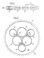
- Figure 2 is a cross-sectional representation of the irradiator of Figure 1.
- Referring to Figure 1, a gold ore sorting apparatus comprises a rock crusher and classifier 2 to which mined ore is supplied, in which the ore is crushed into lumps and divided into two streams of lumps corresponding to mesh sizes of about 80 mm and 60 mm respectively, while lumps smaller than mesh size about 35 mm are rejected. Both streams of lumps are passed through an irradiator 4 to be described in more detail later, and then all the lumps are caused to pass a y-ray detector assembly 6 arranged to detect y-rays having an energy of 279 keV arising from the decay of 197mAu nuclides and so signifying the presence of gold in the lumps of ore. Each lump of ore is interrogated individually by the detector assembly 6 to establish whether its gold content lies above or below some predetermined concentration. The critical concentration is typically in the range 0.5 to 5 parts per million (ppm), and might for example be set at 1 ppm. Each lump of ore is then passed into a
sorter 8 arranged by means of a cable 7 to respond to signals from the detector assembly 6, and to sort each lump of ore into one of two outlet streams depending on whether the gold concentration in the lump lies above or below the predetermined concentration. - The crusher and classifier 2 and the
sorter 8 may be of types well known in the art, while the detector assembly 6 may be as described more fully in the aforementioned specifications to which reference may be made, the crusher and classifier 2, thesorter 8 and the detector assembly 6 not being the subject of the invention. - Referring to Figure 2, the irradiator 4 comprises a close-packed array of three outer
tubular steel cyclinders 12 and three innertubular steel cyclinders 14, with their longitudinal axes upright, the axes of the threeouter cylinders 12 being at the corners of a notional equilateral triangle, and the axes of the threeinner cylinders 14 being near the mid points of the sides of the triangle. Each of theinner cylinders 14 is of internal diameter 32 cm and each of theouter cylinders 12 is of internal diameter 26 cm. Theouter cylinders 12 and theinner cylinders 14, although close packed, are not contiguous, and each is caused to rotate about its longitudinal axis in a clockwise sense by a drive from an electric motor (not shown). - The
outer cylinders 12 and theinner cylinders 14 adjacent thereto define between them threespaces 15 in whichrespective neutron sources 16 are situated in a horizontal plane at an intermediate position along the length of theouter cylinders 12 and theinner cylinders 14. Eachneutron source 16 comprises a lithium target, at the end of a respective evacuated flight tube (not shown), the three flight tubes emerging via a beam splitter (not shown) from a single proton accelerator (not shown), and the end portion of each flight tube extending parallel to the axes of thecylinders - The
outer cylinders 12, theinner cylinders 14 and theneutron sources 16 are located within acylindrical chamber 20 defined by aconcrete radiation shield 22 which is sufficiently thick to be substantially impervious to y-rays and to neutrons and far enough away so as not to generate an intense field of interfering low energy neutrons. A typical distance is 100 cm. - In operation of the irradiator 4, the streams of ore from the crusher and classifier'2 (see Figure 1) are passed through the
outer cylinders 12 and theinner cylinders 14, the stream of larger lumps of ore being passed through theinner cylinders 14. The accelerator is energised to cause a beam of protons of energy 4.5 MeV to bombard each lithium target, the proton beam being moved around the surface of the target to avoid localized overheating. Fast neutrons of energy between about 0.5 MeV and 2.8 MeV are produced by the reaction 3 Li (p, n) 4 Be, and irradiate the lumps of ore in the adjacentouter cylinders 12 andinner cylinders 14. The neutron flux decreases with distance from thesources 16, hence to provide as uniform an irradiation of the ore lumps as possible theouter cylinders 12 and theinner cylinders 14 are rotated about their . respective longitudinal axes so that each lump of ore traverses the high intensity region of the neutron flux from one of thesources 16 twice, as it passes along thecylinder - If any gold is present in a lump of ore it will be activated by the reaction 197 Au (n, n'y) 197mAu the cross-section for which is a maximum for neutrons of energy about 2.5 MeV. Fast neutrons of energy below 2.8 MeV are capable of bringing about this activation, but have insufficient energy to bring about activation by (n, p) reactions of other elements which are likely to be present in the ore, such as aluminium and silicon.
- The irradiator 4 enables a greater throughput of ore to be irradiated than the irradiators described in the aforementioned specifications and also enables larger lumps of ore to be irradiated. This is because each of the
sources 16 can produce a total neutron flux of about 1012 neutrons/second, about ten times greater than the neutron fluxes available from the sources described in the aforementioned specifications, and because the use of twosources 16 to irradiate each of the larger,inner cylinders 14 means that substantially uniform irradiation and activation of all the lumps of ore in eachinner cylinder 14 is achievable with cylinders of larger diameter than can be satisfactorily irradiated with a single neutron source. - It will be appreciated that the uniformity of irradiation of lumps of ore in the three
inner cylinders 14 may be still further improved by the provision of a fourth neutron source at the position marked A in Figure 2 between the threeinner cylinders 14. - The
inner cylinders 14 and theouter cylinders 12 may have diameters differing from the values given. However to avoid interfering excitations brought about by intermediate energy neutrons all the cylinders are preferably of diameter less than about 50 cm, while to ensure uniform irradiation of the lumps of ore those cylinders which are adjacent to only one neutron source are preferably of diameter less than 35 cm. It will also be appreciated that the number of cylinders need not be six, and that they may be disposed in a different close-packed array. - It will be understood that although the
sources 16 have been described as comprising lithium targets onto which generally vertical beams of protons are incident from a common accelerator, each target may be bombarded by a particle beam from a separate accelerator.
Claims (10)
Applications Claiming Priority (2)
| Application Number | Priority Date | Filing Date | Title |
|---|---|---|---|
| GB8310991 | 1983-04-22 | ||
| GB838310991A GB8310991D0 (en) | 1983-04-22 | 1983-04-22 | Ore irradiator |
Publications (2)
| Publication Number | Publication Date |
|---|---|
| EP0144342A1 EP0144342A1 (en) | 1985-06-19 |
| EP0144342B1 true EP0144342B1 (en) | 1987-07-01 |
Family
ID=10541515
Family Applications (1)
| Application Number | Title | Priority Date | Filing Date |
|---|---|---|---|
| EP84901606A Expired EP0144342B1 (en) | 1983-04-22 | 1984-04-18 | Ore irradiator |
Country Status (11)
| Country | Link |
|---|---|
| US (1) | US4898709A (en) |
| EP (1) | EP0144342B1 (en) |
| JP (1) | JPS60501128A (en) |
| AU (1) | AU561481B2 (en) |
| BR (1) | BR8406807A (en) |
| CA (1) | CA1218474A (en) |
| DE (1) | DE3464522D1 (en) |
| FI (1) | FI844766A0 (en) |
| GB (1) | GB8310991D0 (en) |
| WO (1) | WO1984004393A1 (en) |
| ZA (1) | ZA842953B (en) |
Families Citing this family (7)
| Publication number | Priority date | Publication date | Assignee | Title |
|---|---|---|---|---|
| GB8331911D0 (en) * | 1983-11-30 | 1984-01-04 | Atomic Energy Authority Uk | Ore irradiator |
| JPH0313000U (en) * | 1989-06-19 | 1991-02-08 | ||
| US6577697B2 (en) | 1997-07-09 | 2003-06-10 | Southwest Research Institute | Field analysis of geological samples using delayed neutron activation analysis |
| US6438189B1 (en) * | 1998-07-09 | 2002-08-20 | Numat, Inc. | Pulsed neutron elemental on-line material analyzer |
| US8903035B2 (en) | 2008-07-31 | 2014-12-02 | Battelle Energy Alliance, Llc | Neutron absorbers and methods of forming at least a portion of a neutron absorber |
| US8229054B2 (en) * | 2008-07-31 | 2012-07-24 | Battelle Energy Alliance, Llc | Methods for absorbing neutrons |
| US20170010227A1 (en) * | 2014-02-20 | 2017-01-12 | Applied Physics Instruments Api Oy | A measurement system for gamma activation analysis |
Family Cites Families (7)
| Publication number | Priority date | Publication date | Assignee | Title |
|---|---|---|---|---|
| US2816242A (en) * | 1953-05-19 | 1957-12-10 | Schlumberger Well Surv Corp | Neutron sources |
| GB861316A (en) * | 1957-12-21 | 1961-02-15 | Nobel Bozel | Method for industrial radiochemical treatment and radiochemical reactor |
| US3400290A (en) * | 1965-08-25 | 1968-09-03 | Dresser Ind | Static atmosphere ion beam accelerator having a movable target |
| US3325371A (en) * | 1966-04-01 | 1967-06-13 | Stanton Richard Myles | Apparatus and method for breeding nuclear fuel |
| US3911282A (en) * | 1973-11-01 | 1975-10-07 | Dresser Ind | Axial ion beam accelerator tube having a wobbled target |
| GB2055465B (en) * | 1979-06-14 | 1983-10-19 | Atomic Energy Authority Uk | Determining gold content |
| GB2101304B (en) * | 1981-06-10 | 1985-06-12 | Atomic Energy Authority Uk | Gold ore sorting |
-
1983
- 1983-04-22 GB GB838310991A patent/GB8310991D0/en active Pending
-
1984
- 1984-04-18 BR BR8406807A patent/BR8406807A/en unknown
- 1984-04-18 DE DE8484901606T patent/DE3464522D1/en not_active Expired
- 1984-04-18 JP JP59501701A patent/JPS60501128A/en active Granted
- 1984-04-18 EP EP84901606A patent/EP0144342B1/en not_active Expired
- 1984-04-18 WO PCT/GB1984/000132 patent/WO1984004393A1/en active IP Right Grant
- 1984-04-18 AU AU28617/84A patent/AU561481B2/en not_active Ceased
- 1984-04-19 CA CA000452477A patent/CA1218474A/en not_active Expired
- 1984-08-30 ZA ZA842953A patent/ZA842953B/en unknown
- 1984-12-04 FI FI844766A patent/FI844766A0/en not_active Application Discontinuation
-
1987
- 1987-07-20 US US07/075,213 patent/US4898709A/en not_active Expired - Fee Related
Also Published As
| Publication number | Publication date |
|---|---|
| JPS60501128A (en) | 1985-07-18 |
| AU2861784A (en) | 1984-11-19 |
| AU561481B2 (en) | 1987-05-07 |
| ZA842953B (en) | 1985-08-28 |
| EP0144342A1 (en) | 1985-06-19 |
| DE3464522D1 (en) | 1987-08-06 |
| WO1984004393A1 (en) | 1984-11-08 |
| CA1218474A (en) | 1987-02-24 |
| FI844766L (en) | 1984-12-04 |
| JPS6342226B2 (en) | 1988-08-22 |
| BR8406807A (en) | 1985-03-19 |
| US4898709A (en) | 1990-02-06 |
| GB8310991D0 (en) | 1983-05-25 |
| FI844766A0 (en) | 1984-12-04 |
Similar Documents
| Publication | Publication Date | Title |
|---|---|---|
| Halmshaw | Industrial radiology: theory and practice | |
| US6907097B2 (en) | Cylindrical neutron generator | |
| US2707555A (en) | Beryl ore selector | |
| EP0144342B1 (en) | Ore irradiator | |
| SU1255037A3 (en) | Device for grading pieces of auriferous ore in accordance with gold content thereof | |
| US11927553B2 (en) | Rapid ore analysis to enable bulk sorting using gamma-activation analysis | |
| JPS60501345A (en) | ore sorting equipment | |
| GB2101304A (en) | Gold ore sorting | |
| JP2003315289A (en) | Inspection and analysis device using neutron generating device | |
| US4340443A (en) | Analysis of gold-containing materials | |
| CA2138503C (en) | Method and apparatus for the classification of particulate matter | |
| JPS60198100A (en) | Target for generating neutron | |
| GB2150737A (en) | Lithium target | |
| CA2198990C (en) | Diamond detection | |
| US4696782A (en) | Ore irradiator | |
| GB2055465A (en) | Determining Gold Content | |
| WO1997011388A1 (en) | Method and apparatus for detecting and identifying fissionable material | |
| RU2238545C2 (en) | Method for detection, indentification and localization of organic substances, including explosive and narcotic substnaces, with use of impulse flow of fast neutrons | |
| JPH0888098A (en) | Cyclotron and its accelerating procedure | |
| WO2020152620A1 (en) | Method and system for irradiating and activating an object | |
| Desai et al. | Implications of stable strange quark matter for large binding energy | |
| Ricci | New system for activation analysis with thick-target, 110-MeV electron bremsstrahlung | |
| Turkevich et al. | Reactions of Complex Nuclei with Pions in the Hundred GeV Range | |
| AU7895398A (en) | Analysis of auriferous ore | |
| Palmer et al. | Non-destructive evaluation series |
Legal Events
| Date | Code | Title | Description |
|---|---|---|---|
| PUAI | Public reference made under article 153(3) epc to a published international application that has entered the european phase |
Free format text: ORIGINAL CODE: 0009012 |
|
| 17P | Request for examination filed |
Effective date: 19841221 |
|
| AK | Designated contracting states |
Designated state(s): DE FR GB SE |
|
| 17Q | First examination report despatched |
Effective date: 19860917 |
|
| GRAA | (expected) grant |
Free format text: ORIGINAL CODE: 0009210 |
|
| AK | Designated contracting states |
Kind code of ref document: B1 Designated state(s): DE FR GB SE |
|
| ET | Fr: translation filed | ||
| REF | Corresponds to: |
Ref document number: 3464522 Country of ref document: DE Date of ref document: 19870806 |
|
| PLBE | No opposition filed within time limit |
Free format text: ORIGINAL CODE: 0009261 |
|
| STAA | Information on the status of an ep patent application or granted ep patent |
Free format text: STATUS: NO OPPOSITION FILED WITHIN TIME LIMIT |
|
| 26N | No opposition filed | ||
| PGFP | Annual fee paid to national office [announced via postgrant information from national office to epo] |
Ref country code: GB Payment date: 19890331 Year of fee payment: 6 |
|
| PGFP | Annual fee paid to national office [announced via postgrant information from national office to epo] |
Ref country code: SE Payment date: 19890420 Year of fee payment: 6 |
|
| PGFP | Annual fee paid to national office [announced via postgrant information from national office to epo] |
Ref country code: DE Payment date: 19890421 Year of fee payment: 6 |
|
| PGFP | Annual fee paid to national office [announced via postgrant information from national office to epo] |
Ref country code: FR Payment date: 19890427 Year of fee payment: 6 |
|
| PG25 | Lapsed in a contracting state [announced via postgrant information from national office to epo] |
Ref country code: GB Effective date: 19900418 |
|
| PG25 | Lapsed in a contracting state [announced via postgrant information from national office to epo] |
Ref country code: SE Effective date: 19900419 |
|
| GBPC | Gb: european patent ceased through non-payment of renewal fee | ||
| PG25 | Lapsed in a contracting state [announced via postgrant information from national office to epo] |
Ref country code: FR Effective date: 19901228 |
|
| PG25 | Lapsed in a contracting state [announced via postgrant information from national office to epo] |
Ref country code: DE Effective date: 19910101 |
|
| REG | Reference to a national code |
Ref country code: FR Ref legal event code: ST |
|
| EUG | Se: european patent has lapsed |
Ref document number: 84901606.8 Effective date: 19910115 |