EP0144185B1 - Electrochemical device - Google Patents
Electrochemical device Download PDFInfo
- Publication number
- EP0144185B1 EP0144185B1 EP84307964A EP84307964A EP0144185B1 EP 0144185 B1 EP0144185 B1 EP 0144185B1 EP 84307964 A EP84307964 A EP 84307964A EP 84307964 A EP84307964 A EP 84307964A EP 0144185 B1 EP0144185 B1 EP 0144185B1
- Authority
- EP
- European Patent Office
- Prior art keywords
- solid electrolyte
- conductors
- electrochemical device
- conductor
- electrolyte body
- Prior art date
- Legal status (The legal status is an assumption and is not a legal conclusion. Google has not performed a legal analysis and makes no representation as to the accuracy of the status listed.)
- Expired
Links
Images


Classifications
-
- G—PHYSICS
- G01—MEASURING; TESTING
- G01N—INVESTIGATING OR ANALYSING MATERIALS BY DETERMINING THEIR CHEMICAL OR PHYSICAL PROPERTIES
- G01N27/00—Investigating or analysing materials by the use of electric, electrochemical, or magnetic means
- G01N27/26—Investigating or analysing materials by the use of electric, electrochemical, or magnetic means by investigating electrochemical variables; by using electrolysis or electrophoresis
- G01N27/403—Cells and electrode assemblies
- G01N27/406—Cells and probes with solid electrolytes
- G01N27/407—Cells and probes with solid electrolytes for investigating or analysing gases
- G01N27/4071—Cells and probes with solid electrolytes for investigating or analysing gases using sensor elements of laminated structure
-
- G—PHYSICS
- G01—MEASURING; TESTING
- G01N—INVESTIGATING OR ANALYSING MATERIALS BY DETERMINING THEIR CHEMICAL OR PHYSICAL PROPERTIES
- G01N27/00—Investigating or analysing materials by the use of electric, electrochemical, or magnetic means
- G01N27/26—Investigating or analysing materials by the use of electric, electrochemical, or magnetic means by investigating electrochemical variables; by using electrolysis or electrophoresis
- G01N27/403—Cells and electrode assemblies
- G01N27/406—Cells and probes with solid electrolytes
- G01N27/4067—Means for heating or controlling the temperature of the solid electrolyte
-
- G—PHYSICS
- G01—MEASURING; TESTING
- G01N—INVESTIGATING OR ANALYSING MATERIALS BY DETERMINING THEIR CHEMICAL OR PHYSICAL PROPERTIES
- G01N27/00—Investigating or analysing materials by the use of electric, electrochemical, or magnetic means
- G01N27/26—Investigating or analysing materials by the use of electric, electrochemical, or magnetic means by investigating electrochemical variables; by using electrolysis or electrophoresis
- G01N27/416—Systems
- G01N27/417—Systems using cells, i.e. more than one cell and probes with solid electrolytes
Definitions
- the present invention relates generally to an electrochemical device, and more particularly to a device which comprises a laminated electrochemical cell having planar solid electrolyte bodies.
- oxygen sensors to detect the oxygen concentration of an exhaust gas from internal combustion engines of automotive vehicles.
- the typical examples of such oxygen sensors include: an oxygen sensor which comprises a tubular body of oxygen-ion conductive solid electrolyte such as zirconia ceramics, and electrodes of platinum or the like provided on both inner and outer surfaces of the tubular solid electrolyte body, and which operates to determine the oxygen concentration according to the principle of an oxygen concentration cell; an oxygen sensor similar to the above, which incorporates a heater which enables the sensor to operate at a relatively low exhaust gas temperature; and a so-called "lean-burn" sensor suitable for detecting the oxygen concentration of an exhaust gas which is produced at lean air-fuel ratios, i.e., an exhaust gas having a larger oxygen content.
- electrochemical devices such as sensing and pumping elements for detecting hydrogen, nitrogen, carbon dioxide gas, etc. These sensing and pumping elements operate according to the principle of a concentration cell, like the oxygen sensor
- each conductor such as a lead for one of the electrodes is sandwiched between a pair of adjacent planar solid electrolyte bodies, that is, the conductors are embedded in the mass of the solid electrolyte. Accordingly, the conductors are held in direct contact with the solid electrolyte.
- the electrochemical device is adapted such that a voltage is applied, for example, to an oxygen pumping element through such conductors (conductive leads), parts of the solid electrolyte contacting the conductors are electrolyzed and tend to deteriorate.
- the solid electrolyte bodies have potential problems of cracking, and deterioration or loss of ion conductivity and other characteristics.
- the electrolysis of the solid electrolyte may cause an erroneous measurement between the conductor and a measuring electrode, which affects an electromotive force to be measured, and causes a measurement error of the electrochemical device.
- an air gap may exist between the conductor and the solid electrolyte bodies sandwiching the conductor. This air gap accommodates an oxygen gas, which may cause degradation of the response and generation of output noises of the sensing device.
- Another object of the invention is the provision of a highly reliable electrochemical device of laminar or integrally laminated type, which suffers minimum noises and measurement errors caused by the conductors embedded in the solid electrolyte, and which is thus improved in response.
- FR-A-2451580 shows, typically in Figs. 2 and 3, an electrochemical device having stacked solid electrolyte bodies, a pair of electrodes in contact with one of the electrolyte bodies and conductive leads for the electrodes.
- One such lead is located between two solid electrolyte bodies in contact with one body,-and is exposed to a gaseous fluid such as air and is not insulated from the body which it contacts.
- the other lead which is not sandwiched between two electrolyte bodies, is insulated by an insulating layer from the adjacent electrolyte body while being exposed to the gas being measured.
- an electrochemical device as set out in claim 1.
- an electrical insulation layer or layers electrically insulate an electric conductor or conductors, such as a lead connected to one of the electrodes, which are disposed between two adjacent solid electrolyte bodies.
- the insulation layers are effective to prevent cracking, deterioration or other troubles with the solid electrolyte bodies arising from the electrolysis. Further, the insulation layers serve as effective means for preventing output noises of the electrochemical device which would otherwise be produced due to the uninsulated conductors.
- the electrochemical device of the invention is highly reliable in operation, and is suitable for use as various sensors for determining or controlling the concentration of specific components of a fluid associated with electrode reaction, such as nitrogen, carbon dioxide and hydrogen as well as oxygen, in particular as an oxygen sensor for determining the oxygen concentration of an exhaust gas emitted from an internal combustion engine.
- a fluid associated with electrode reaction such as nitrogen, carbon dioxide and hydrogen
- oxygen in particular as an oxygen sensor for determining the oxygen concentration of an exhaust gas emitted from an internal combustion engine.
- the present invention finds its primary industrial significance in such fields of technology.
- the conductor or conductors are made of a material including elements of the platinum group, and the electrical insulation layer is made of a material consisting essentially of alumina or spinel.
- a substantial portion of the conductor is sandwiched on opposite sides thereof by two electrical insulation layers one of which is disposed between said one side of the conductor and said one of the two adjacent solid electrolyte bodies, and the other of which is disposed between the other side of the conductor and the other of said two adjacent solid electrolyte bodies.
- the measuring and reference electrodes generate ah electromotive force which varies with a difference in concentration of the measuring component between the gaseous fluid and the reference gas.
- the second electrolyte body has a cavity into which the reference gas is introduced, so that one of the electrodes is exposed to the reference gas within the cavity.
- the spacer member has a cavity to and from which said component of said gaseous fluid is introduced and removed upon application of a voltage between said pumping electrodes.
- the pumping electrode connected to the said first one of said first conductors, and the measuring electrode connected to the said first one of the said second conductors, may both be exposed to the atmosphere within said cavity formed in the spacer member.
- the oxygen concentration sensor comprises a lean-burn sensor which is an integral lamination of a pumping cell 2 of laminar structure and a sensing cell 4 also of laminar structure via a planar spacer member 8 sandwiched therebetween.
- the spacer member 8 is made of a solid electrolyte material such as zirconia ceramics and has a cavity 6.
- the pumping cell 2 includes a solid electrolyte body 10 of plate-like or planar shape made of zirconia ceramics or the like, and a porous outer pumping electrode 12 made of platinum, for example, which is disposed on one of opposite sides or surfaces of the planar solid electrolyte body 10. More specifically, the planar solid electrolyte body 10 is provided with the outer pumping electrode 12 on its surface on the side which is exposed to an exhuast gas or other gases to be measured.
- the outer pumping electrode 12 is connected to an external power source through a conductor in the form of a lead 14 extending from the electrode 12.
- the outer pumping electrode 12 is covered with a porous protective layer 16 formed of porous spinel or the like by means of plasma spray technique, screen printing or the like and exposed to the measurement gas through the protective layer 16.
- the pumping cell 2 further includes an electrical insulation layer 20 which is disposed on the other side of the planar solid electrolye body 10.
- the insulation layer 20 has a cutout 18 of a size corresponding to the size of the outer pumping electrode 12.
- An inner pumping electrode 22 is disposed on the side of the insulation layer 20 remote from the solid electrolyte body 10 such that the electrode 22 is aligned with the cutout 18 formed in the insulation layer 20.
- the inner pumping electrode 22 is provided with a lead 24 of a conductive material which extends over the insulation layer 20 so that its end is located outside the pumping cell 2.
- Another electric insulation layer 26 is disposed on the side of the lead 24 remote from the insulation layer 20, whereby the lead 24 is sandwiched on its opposite sides by the two electrical insulation layers 20 and 26. In other words, the lead 24 is covered by the insulation layers 20, 26 at its upper and lower surfaces except the outer end portion which is exposed outside the pumping cell 2 for electric connection 1 to the external power source.
- the pumping cell 2 comprises an oxygen pumping cell which includes a pair of pumping electrodes, i.e., the outer pumping electrode 12 formed on one side of the solid electrolyte body 10, and the inner pumping electrode 22 disposed adjacent to the cutout 18 in the insulation layer 20 on the other side of the solid electrolyte body 10.
- the oxygen pumping cell operates in the well known manner, to introduce the oxygen in the outside measurement gas into the cavity 6 formed in the spacer member 8, or to discharge or remove the oxygen from the cavity 6 out into the outside measurement gas, according to the direction of flow of an electric current between the electrodes 12 and 22.
- the sensing cell 4 includes a planar solid electrolyte body 28 made of zirconia ceramics or the like, and further includes an inner measuring electrode 32 and an outer measuring electrode 30 which adhere to opposite surfaces of the planar solid electrolyte body 28.
- an oxygen concentration cell is constituted.
- an electrical insulation layer 34 which has a cutout 36 aligned with the inner measuring electrode 32, so that the inner electrode 32 is disposed on the solid electrolyte body 28 via the cutout 36.
- the inner measuring electrode 32 is connected to a lead 38 which is electrically insulated by the insulation layer 34 with respect to the planar solid electrolyte body 28.
- the lead 38 extends out of the sensing cell 4 so that its end opposite to the electrode 30 is connected to a suitable measuring device.
- the outer measuring electrode 30 is connected via its lead 40 to the external measuring device, and covered at its outer surface with a porous protective layer 42 similar to the aforementioned porous protective layer 16. That is, the protective layer 42 protects the outer measuring electrode 30 from direct contact of the measurement gas.
- a porous protective layer 42 similar to the aforementioned porous protective layer 16. That is, the protective layer 42 protects the outer measuring electrode 30 from direct contact of the measurement gas.
- the laminar pumping cell 2 and the laminar sensing cell 4, and the spacer member 8 are laminated with the spacer member 8 sandwiched between the two cells 2, 4, whereby the intended laminar electrochemical cell (sensing element) is fabricated.
- the conductors interposed between the two masses of solid electrolyte i.e., the leads 24 and 38 of the electrodes 22 and 32 are electrically insulated at their substantive portions, that is, at the portions which are exposed to an elevated temperature, with respect to at least one of the two masses of solid electrolyte. Stated more particularly with reference to Fig.
- the lead 24 of the inner pumping electrode 22 is sandwiched by the electric insulation layers 20 and 26, and thus electrically insulated with respect to the planar solid electrolyte body 10 and the spacer member 8 (made of solid electrolyte) which are disposed on both sides of the lead 24.
- the lead 38 of the inner measuring electrode 32 is electrically insulated by the insulation layer 34 with respect to the planar solid electrolyte body 28 on one side of the lead 38.
- the portions of the solid electrolyte members which would otherwise contact the lead 24 will not be deteriorated due to electrolysis upon application of a pumping voltage between the inner and outer pumping electrodes 12, 22 to operate the pumping cell 2 as an oxygen pumping cell.
- the spacer member 8 and the planar solid electrolyte body 10 are protected against otherwise possible troubles of cracking, and deterioration of ion conductivity.
- the insulation layer 34 prevents the lead 38 of the inner measuring electrode 32 from directly contacting the planar solid electrolyte body 28.
- the insulation layer 34 effectively eliminates otherwise possible troubles: such as measurement errors based on measurements of an electromotive force between the conductor lead and the outer measuring electrode; degradation of the response characteristics of the sensing element due to presence of the oxygen gas staying within an air gap existing between the lead of the inner measuring electrode and the planar solid electrolyte bodies; and generation of output noises of the sensing element.
- the spacer member 8 is electrically insulated by the insulation layers 20, 26 and 34 with respect to the electrodes 12, 22 and 32 and their leads 14,24 and 38. Therefore, it is not necessary to interpose an electrical insulation layer between the lead 38 and the spacer member 8.
- the insulation layers 20, 26 and 34 for electrical insulation of the conductors, i.e., leads 24 and 38 from the solid electrolyte materials 10, 8, 28, are preferably ceramic layers which comprises alumina or spinel as a major component.
- the insulation layers may be made of ceramics whose major component is borosilicate glass or mullite. It is desired that the insulation layers 20, 26 and 34 are fabricated to have a thickness as small as possible within a range in which they can provide sufficient electric insulating capability. preferably, the thickness should be less than 100 urn, and more preferably less than 50 pm.
- the insulation layers 20, 26 and 34 are made porous, for effectively minimizing a stress due to difference in coefficient of thermal expansion between these insulation layers and the solid electrolyte materials 8, 10, 28.
- the porous structure of the insulation layers is effective for preventing flake-off of these layers and the solid electrolyte members.
- the electrical insulation layers 20 and 34 are formed on the planar solid electrolyte bodies 10 and 28, respectively, by applying a paste of ceramic powder, for example by a screen-printing method, to green sheets of the planar solid electrolyte bodies 10, 28. Subsequently, the electrode 22 and its lead 24, and the electrode 32 and its lead 38, are similarly printed on the printed insulation layers 20 and 34, respectively. The insulation layer 26 is similarly printed on the printed lead 24 on the insulation layer 20.
- the solid electrolyte materials and electrical insulation materials are concurrently sintered.
- the electrodes 12, 22, 30 and 32, and their leads 14, 24, 40 and 38 are co-fired with the solid electrolyte and electrical insulation materials.
- these electrodes and leads which are electric conductors are preferably formed by screen printing, using as major components elements of the platinum group including platinum, palladium, rhodium, iridium, ruthenium and osmium.
- the printed layers are finally fired to form the intended layers of electrodes and leads concurrently with the solid electrolyte and insulation layers.
- the solid electrolyte materials used according to the invention may be aluminium nitride, SrCe0 3 , solid solution of bismuth oxide and oxide of rare earth element, Lai-,Ca.YO3-,,, or the like, in place of the previously indicated zirconia ceramics.
- the oxygen sensor illustrated in Figs. 1 and 2 as an electrochemical device of the invention is suitably used as a lean-burn sensor for controlling an engine of the type emitting an exhaust gas of lean air-fuel ratios whose oxygen partial pressure is higher than that of the stoichiometric air-fuel ratio.
- the planar solid electrolyte bodies 10 and 28 may not be held at a sufficiently high temperature. In this condition, the oxygen sensor is not sufficiently capable.
- the oxygen sensor is generally provided with a heater.
- the principle of the present invention is also applicable to such a heater-equipped sensor, one example of which is illustrated in Figs 3 and 4.
- the modified oxygen sensor of Figs. 3 and 4 is different from the sensor of Figs. 1 and 2 in that a heater 44 is provided on the side of the sensing element 4. Since the arrangements of the pumping and sensing cells 2 and 4 are identical to those of the aforementioned sensor of Figs. 1 and 2, the same reference numerals . are used in Figs. 3 and 4 to identify the corresponding parts, and the following description of this modified embodiment refers only to the heater 44 for avoiding repeated description of the same parts.
- the heater 44 is a lamination of a heating element 46 with leads 48, an inner and an outer gastight ceramic layer 50, 52 disposed on opposite sides of the heating element 46, and an electrical insulation layer 54 which is disposed between the inner gastight ceramic layer 50 and the planar solid electrolyte body 28 and which has the same configuration as the ceramic layer 50.
- the inner and outer gastight layers 50 and 52 are provided to restrain vaporization of platinum and other components of a composition of the heating element 46 and leads 48.
- the electrical insulation layer 54 is formed of the same materials as used for the insulation layers 20, 26 and 34 provided in the pumping and sensing elements 2 and 4.
- the insulation layer 54 is laminated on the surface of the planar solid electrolyte body 28 on which the outer measuring electrode 30 is disposed.
- the insulation layer 54 provides a barrier to protect the sensing cell 4 against otherwise possible leakage of electric current from the heating element 46 and leads 48 through the gastight ceramic layer 50, thereby protecting the sensing cell 4 from an influence of such leakage current.
- a porous protective layer 42 is superposed on the heater 44.
- the protective layer 42 protects the surface of the outer measuring electrode 30 which is exposed to the measurement gas through a cutout in the insulation layer 54, a cutout in the inner gastight ceramic layer 50, a void defined by the heating element 46, and a cutout in the outer gastight ceramic layer 52.
- the protective layer 42 also serves to protect an end portion of the lead 40 adjacent to the measuring electrode 30.
- the electrochemical device having the heater 44 uses the insulation layers which are similar in construction and location to those used in the device of Figs. 1 and 2. Accordingly, these insulation layers attain the same functions as previously described.
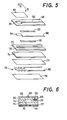
- FIG. 5 Another modified oxygen sensor as an electrochemical device of the invention is illustrated in Figs. 5 and 6.
- the oxygen sensor of Figs. 5 and 6, which is a modified embodiment of the electrochemical device of the invention, is a sensor to measure an exhaust gas which is produced in combustion of an air-fuel mixture at the stoichiometric ratio and which therefore has a low oxygen content.
- This oxygen sensor includes a planar solid electrolyte body 56 which is provided on its outer surface with a measuring electrode 58.
- the electrode 58 is connected via a lead 60 to an external device and exposed to the measurement gas through a porous protective layer 62 which covers the electrode 58.
- a reference electrode 64 with a lead 66 is disposed on the inner surface of the planar solid electrolyte body 56.
- a substantive portion of the lead 66 that is, the portion of the lead 66 which is exposed to an elevated temperature, is sandwiched by two electrical insulation layers 68 and 70.
- a U-shaped solid electrolyte body 72 and a planar solid electrolyte body 74 are superposed such that the U-shaped solid electrolyte body 72 is sandwiched by the two planar solid electrolyte bodies 56 and 74.
- the three solid electrolyte bodies 56, 72 and 74 cooperate to define a cavity 76 which is open at its one end to the ambient atmosphere.
- the reference electrode 64 is positioned so as to be exposed to a reference gas such as an ambient atmosphere introduced into the cavity 76.
- a heating element 78 sandwiched by a pair of gastight ceramic layers 77, 79 which protect and electrically insulate the heating element 78.
- the heater heats a portion of the planar solid electrolyte body 56 adjacent to the electrodes 58, 64, to an elevated temperature so as to maintain a sufficient oxygen-ion conductivity of that portion of the solid electrolyte body 56.
- the conductor disposed between the solid electrolyte bodies 56 and 72 that is, the lead 66 of the reference electrode 64 is sandwiched at its opposite surfaces by a pair of electrical insulation layers 68 and 70, and thereby electrically insulated with respect to the electrolyte bodies 56 and 72.
- the insulation layers 68, 70 prevent the lead 66 from directly contacting the solid electrolyte bodies 56, 72, and thereby eliminating an otherwise possible chance of erroneous measurement of an electromotive force between the lead 66, and the measuring electrode 58 which is more or less opposite to the lead 66.
- the output noises due to the lead 66 are effectively prevented.
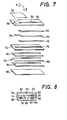
- Figs. 7 and 8 illustrate a further embodiment of the invention wherein the oxygen sensor is different from the sensor of Figs. 5 and 6 in location and environments of the heater 78.
- the heating element 78 and its leads 80 of this modified embodiment of the oxygen sensor are sandwiched at their substantive portions by a pair of electrical insulation layers 82, 84.
- the end portions of the leads 80 remote from the heating element 78 are exposed for electric connection to an external power source.
- These insulation layers 82, 84 laminated to sandwich the heating element 78 and the leads 80 are sandwiched by a solid electrolyte body 86, and the previously indicated U-shaped solid electrolyte body 72 having the cavity 76.
- the lead 66 of the reference electrode 64 is electrically insulated over its entire length by a pair of elongate insulation layers 68, 70.
- the heating element 78 were directly embedded between the solid electrolyte bodies 72 and 86, a portion of the electric current flowing in the heating element 78 and the leads 80 would leak through the solid electrolyte bodies 72, 86 when the heating element 78 is energized to heat the oxygen sensor, more precisely a portion of the planar solid electrolyte body 56 adjacent to the measuring and reference electrodes 58 and 64.
- the heating element 78 not only the heating element 78 but also the leads 80 are electrically insulated relative to the solid electrolyte bodies 72 and 86 by the upper and lower electrical insulation layers 82 and 84, respectively.
- the electrolyte bodies 72, 86 are separated or spaced away from the heating element 78 and the leads 80 by the insulation layers 82, 84, and thus kept free from electrolysis due to energization of the heating element 78. Consequently, otherwise possible deterioration and cracking troubles with the solid electrolyte bodies 72, 86 due to the electrolysis will be effectively prevented.
- the insulation layer 82 serves to hinder a leakage flow of current from reaching the reference electrode 64 through the solid electrolyte body 72, thus preventing an unfavourable influence of such leakage current upon the reference electrode 64.
- electrochemical devices according to the invention have been illustrated in the form of a sensor having an oxygen concentration cell, or a lean-burn sensor having an oxygen pumping cell as well as a sensing cell, various other forms of the electrochemical device may be constructed according to the invention. Further, the invention may be applied to an electrochemical pump, polarographic electrochemical cell, and the like.
Description
- The present invention relates generally to an electrochemical device, and more particularly to a device which comprises a laminated electrochemical cell having planar solid electrolyte bodies.
- There have been known various electrochemical devices using solid electrolyte, for example as oxygen sensors to detect the oxygen concentration of an exhaust gas from internal combustion engines of automotive vehicles. The typical examples of such oxygen sensors include: an oxygen sensor which comprises a tubular body of oxygen-ion conductive solid electrolyte such as zirconia ceramics, and electrodes of platinum or the like provided on both inner and outer surfaces of the tubular solid electrolyte body, and which operates to determine the oxygen concentration according to the principle of an oxygen concentration cell; an oxygen sensor similar to the above, which incorporates a heater which enables the sensor to operate at a relatively low exhaust gas temperature; and a so-called "lean-burn" sensor suitable for detecting the oxygen concentration of an exhaust gas which is produced at lean air-fuel ratios, i.e., an exhaust gas having a larger oxygen content. Also known in the art are electrochemical devices such as sensing and pumping elements for detecting hydrogen, nitrogen, carbon dioxide gas, etc. These sensing and pumping elements operate according to the principle of a concentration cell, like the oxygen sensor indicated above.
- In such electrochemical devices, solid electrolyte materials have been generally used in the form of a tubular body which has an elongate bore closed at its one end. In recent years, however, it has been attempted to replace the tubular solid electrolyte body with a solid electrolyte body of planar shape, as disclosed in U.S. Patent No. 4,334,974, in view of relatively low productivity and high cost of manufacture of the solid electrolyte bodies of tubular shape, and from the standpoint of easy assembling of parts with the solid electrolyte body. When such planar solid electrolyte bodies are employed, suitable electrodes are disposed in contact with the surfaces of the planar body of solid electrolyte, and the electrolyte bodies and other parts are assembled into a laminar structure constituting an electrochemical cell.
- In such an electrochemical cell wherein planar or plate-like bodies of solid electrolyte are laminated, each conductor such as a lead for one of the electrodes is sandwiched between a pair of adjacent planar solid electrolyte bodies, that is, the conductors are embedded in the mass of the solid electrolyte. Accordingly, the conductors are held in direct contact with the solid electrolyte. Since the electrochemical device is adapted such that a voltage is applied, for example, to an oxygen pumping element through such conductors (conductive leads), parts of the solid electrolyte contacting the conductors are electrolyzed and tend to deteriorate. Thus, the solid electrolyte bodies have potential problems of cracking, and deterioration or loss of ion conductivity and other characteristics. Further, the electrolysis of the solid electrolyte may cause an erroneous measurement between the conductor and a measuring electrode, which affects an electromotive force to be measured, and causes a measurement error of the electrochemical device. In addition, an air gap may exist between the conductor and the solid electrolyte bodies sandwiching the conductor. This air gap accommodates an oxygen gas, which may cause degradation of the response and generation of output noises of the sensing device.
- It is accordingly an object of the present invention, which was made in the light of the above situations in the prior art, to provide an electrochemical device which is effectively protected against electrolysis of parts of the solid electrolyte adjacent to the conductors embedded in the solid electrolyte.
- Another object of the invention is the provision of a highly reliable electrochemical device of laminar or integrally laminated type, which suffers minimum noises and measurement errors caused by the conductors embedded in the solid electrolyte, and which is thus improved in response.
- It is mentioned that FR-A-2451580 shows, typically in Figs. 2 and 3, an electrochemical device having stacked solid electrolyte bodies, a pair of electrodes in contact with one of the electrolyte bodies and conductive leads for the electrodes. One such lead is located between two solid electrolyte bodies in contact with one body,-and is exposed to a gaseous fluid such as air and is not insulated from the body which it contacts. The other lead, which is not sandwiched between two electrolyte bodies, is insulated by an insulating layer from the adjacent electrolyte body while being exposed to the gas being measured.
- According to the present invention, there is provided an electrochemical device as set out in claim 1.
- In the electrochemical device constructed as described above, an electrical insulation layer or layers electrically insulate an electric conductor or conductors, such as a lead connected to one of the electrodes, which are disposed between two adjacent solid electrolyte bodies. With the provision of the insulation layers, the solid electrolyte bodies are substantially completely protected against electrolysis which would otherwise occur due to application of a voltage to the conductors. Thus, the insulation layers are effective to prevent cracking, deterioration or other troubles with the solid electrolyte bodies arising from the electrolysis. Further, the insulation layers serve as effective means for preventing output noises of the electrochemical device which Would otherwise be produced due to the uninsulated conductors. Accordingly, the electrochemical device of the invention is highly reliable in operation, and is suitable for use as various sensors for determining or controlling the concentration of specific components of a fluid associated with electrode reaction, such as nitrogen, carbon dioxide and hydrogen as well as oxygen, in particular as an oxygen sensor for determining the oxygen concentration of an exhaust gas emitted from an internal combustion engine. The present invention finds its primary industrial significance in such fields of technology.
- According to a preferred form of the invention, the conductor or conductors are made of a material including elements of the platinum group, and the electrical insulation layer is made of a material consisting essentially of alumina or spinel.
- In accordance with one advantageous embodiment of the invention, a substantial portion of the conductor is sandwiched on opposite sides thereof by two electrical insulation layers one of which is disposed between said one side of the conductor and said one of the two adjacent solid electrolyte bodies, and the other of which is disposed between the other side of the conductor and the other of said two adjacent solid electrolyte bodies.
- In one embodiment of the invention, of said pair of electrodes, one is a measuring electrode which is exposed to the gaseous fluid, while the other, which is connected to the conductor located between the first and second electrolyte bodies, is a reference electrode which is exposed to a reference gas. The measuring and reference electrodes generate ah electromotive force which varies with a difference in concentration of the measuring component between the gaseous fluid and the reference gas. In one form of this embodiment the second electrolyte body has a cavity into which the reference gas is introduced, so that one of the electrodes is exposed to the reference gas within the cavity.
- According to the invention, there is also provided an electrochemical device as set out in
claim 6. - In a preferred form of this embodiment, the spacer member has a cavity to and from which said component of said gaseous fluid is introduced and removed upon application of a voltage between said pumping electrodes. The pumping electrode connected to the said first one of said first conductors, and the measuring electrode connected to the said first one of the said second conductors, may both be exposed to the atmosphere within said cavity formed in the spacer member.
- Embodiments of the present invention will be given by way of example in the following description to be read in connection with the accompanying drawings in which:
- Fig. 1 is an exploded perspective view of a sensing element of one embodiment of an electrochemical device of the invention in the form of an oxygen sensor;
- Fig. 2 is an elevational schematic view in cross section taken along line 2-2 of Fig. 1;
- Figs. 3, 5 and 7 are exploded perspective views corresponding to Fig. 1, of other embodiments of the electrochemical device of the invention, respectively; and
- Figs. 4, 6 and 8 are elevational schematic views in cross section taken along line 4-4 of Fig. 3, line 6-6 of Fig. 5 and line 8-8 of Fig. 7, respectively.
- Referring to the accompanying drawings illustrating preferred embodiments of the present invention, the arrangement of the invention will be described in detail.
- There is shown in the exploded perspective view of Fig. 1 a sensing element of one example of an oxygen concentration sensor which is one embodiment of an electrochemical device of the invention. The oxygen concentration sensor comprises a lean-burn sensor which is an integral lamination of a
pumping cell 2 of laminar structure and asensing cell 4 also of laminar structure via aplanar spacer member 8 sandwiched therebetween. Thespacer member 8 is made of a solid electrolyte material such as zirconia ceramics and has acavity 6. - The
pumping cell 2 includes asolid electrolyte body 10 of plate-like or planar shape made of zirconia ceramics or the like, and a porousouter pumping electrode 12 made of platinum, for example, which is disposed on one of opposite sides or surfaces of the planarsolid electrolyte body 10. More specifically, the planarsolid electrolyte body 10 is provided with theouter pumping electrode 12 on its surface on the side which is exposed to an exhuast gas or other gases to be measured. Theouter pumping electrode 12 is connected to an external power source through a conductor in the form of alead 14 extending from theelectrode 12. Theouter pumping electrode 12 is covered with a porousprotective layer 16 formed of porous spinel or the like by means of plasma spray technique, screen printing or the like and exposed to the measurement gas through theprotective layer 16. - The
pumping cell 2 further includes anelectrical insulation layer 20 which is disposed on the other side of the planarsolid electrolye body 10. Theinsulation layer 20 has acutout 18 of a size corresponding to the size of theouter pumping electrode 12. Aninner pumping electrode 22 is disposed on the side of theinsulation layer 20 remote from thesolid electrolyte body 10 such that theelectrode 22 is aligned with thecutout 18 formed in theinsulation layer 20. Theinner pumping electrode 22 is provided with alead 24 of a conductive material which extends over theinsulation layer 20 so that its end is located outside thepumping cell 2. Anotherelectric insulation layer 26 is disposed on the side of thelead 24 remote from theinsulation layer 20, whereby thelead 24 is sandwiched on its opposite sides by the twoelectrical insulation layers lead 24 is covered by theinsulation layers pumping cell 2 for electric connection 1 to the external power source. - As described above, the
pumping cell 2 comprises an oxygen pumping cell which includes a pair of pumping electrodes, i.e., theouter pumping electrode 12 formed on one side of thesolid electrolyte body 10, and theinner pumping electrode 22 disposed adjacent to thecutout 18 in theinsulation layer 20 on the other side of thesolid electrolyte body 10. With a voltage applied between these twoelectrodes cavity 6 formed in thespacer member 8, or to discharge or remove the oxygen from thecavity 6 out into the outside measurement gas, according to the direction of flow of an electric current between theelectrodes - In the meantime, the
sensing cell 4 includes a planarsolid electrolyte body 28 made of zirconia ceramics or the like, and further includes aninner measuring electrode 32 and anouter measuring electrode 30 which adhere to opposite surfaces of the planarsolid electrolyte body 28. Thus, an oxygen concentration cell is constituted. Between the two inner andouter measuring electrodes electrical insulation layer 34 which has acutout 36 aligned with theinner measuring electrode 32, so that theinner electrode 32 is disposed on thesolid electrolyte body 28 via thecutout 36. Theinner measuring electrode 32 is connected to alead 38 which is electrically insulated by theinsulation layer 34 with respect to the planarsolid electrolyte body 28. Thelead 38 extends out of thesensing cell 4 so that its end opposite to theelectrode 30 is connected to a suitable measuring device. Theouter measuring electrode 30 is connected via itslead 40 to the external measuring device, and covered at its outer surface with a porousprotective layer 42 similar to the aforementioned porousprotective layer 16. That is, theprotective layer 42 protects theouter measuring electrode 30 from direct contact of the measurement gas. In the above-described arrangement of thesensing cell 4, an electromotive force due to difference in oxygen concentration is measured between theouter measuring electrode 30 which is exposed to the outside measurement gas, and theinner measuring electrode 32 which is exposed to the atmosphere within thecavity 6. - The
laminar pumping cell 2 and thelaminar sensing cell 4, and thespacer member 8 are laminated with thespacer member 8 sandwiched between the twocells leads electrodes lead 24 of theinner pumping electrode 22 is sandwiched by the electric insulation layers 20 and 26, and thus electrically insulated with respect to the planarsolid electrolyte body 10 and the spacer member 8 (made of solid electrolyte) which are disposed on both sides of thelead 24. On the other hand, thelead 38 of theinner measuring electrode 32 is electrically insulated by theinsulation layer 34 with respect to the planarsolid electrolyte body 28 on one side of thelead 38. - In the electrochemical device of the aforementioned construction wherein the
lead 24 of theinner pumping electrode 22 sandwiched by the insulation layers 20, 26 is not in direct contact with thesolid electrolyte members lead 24 will not be deteriorated due to electrolysis upon application of a pumping voltage between the inner andouter pumping electrodes cell 2 as an oxygen pumping cell. Hence, thespacer member 8 and the planarsolid electrolyte body 10 are protected against otherwise possible troubles of cracking, and deterioration of ion conductivity. In this connection, it is noted that thelead 14 of theouter pumping electrode 12, which directly contacts thesolid electrolyte body 10, will not be subject to the previously indicated electrolysis at its portion contacting thesolid electrolyte body 10, because the oxygen in the outside measurement gas is supplied to thesolid electrolyte body 10. - Further, the
insulation layer 34 prevents thelead 38 of theinner measuring electrode 32 from directly contacting the planarsolid electrolyte body 28. Hence, theinsulation layer 34 effectively eliminates otherwise possible troubles: such as measurement errors based on measurements of an electromotive force between the conductor lead and the outer measuring electrode; degradation of the response characteristics of the sensing element due to presence of the oxygen gas staying within an air gap existing between the lead of the inner measuring electrode and the planar solid electrolyte bodies; and generation of output noises of the sensing element. - On the other hand, no insulation layer is disposed between the lead 38 and the
spacer member 8 and these two members are kept in direct contact with each other. However, thespacer member 8 is electrically insulated by the insulation layers 20, 26 and 34 with respect to theelectrodes leads spacer member 8. - The insulation layers 20, 26 and 34 for electrical insulation of the conductors, i.e., leads 24 and 38 from the
solid electrolyte materials solid electrolyte materials - The electrical insulation layers 20 and 34 are formed on the planar
solid electrolyte bodies solid electrolyte bodies electrode 22 and itslead 24, and theelectrode 32 and itslead 38, are similarly printed on the printed insulation layers 20 and 34, respectively. Theinsulation layer 26 is similarly printed on the printedlead 24 on theinsulation layer 20. The thus prepared lamination comprising the printed layers 20, 22, 24 and 26 on the green sheet of theelectrolyte body 10, and the lamination comprising the printed layers 34, 32 and 38 on the green sheet of theelectrolyte body 28, are then laminated with thespacer member 8 sandwiched therebetween, and finally subjected to known co-firing and other processes, whereby the laminatedelectrochemical cells - During a co-firing process as indicated above, the solid electrolyte materials and electrical insulation materials are concurrently sintered. For this reason, it is desired that the
electrodes leads - The solid electrolyte materials used according to the invention may be aluminium nitride, SrCe03, solid solution of bismuth oxide and oxide of rare earth element, Lai-,Ca.YO3-,,, or the like, in place of the previously indicated zirconia ceramics.
- The oxygen sensor illustrated in Figs. 1 and 2 as an electrochemical device of the invention is suitably used as a lean-burn sensor for controlling an engine of the type emitting an exhaust gas of lean air-fuel ratios whose oxygen partial pressure is higher than that of the stoichiometric air-fuel ratio. At a relatively iow temperature of the exhaust gas, however, the planar
solid electrolyte bodies - The modified oxygen sensor of Figs. 3 and 4 is different from the sensor of Figs. 1 and 2 in that a
heater 44 is provided on the side of thesensing element 4. Since the arrangements of the pumping andsensing cells heater 44 for avoiding repeated description of the same parts. - The
heater 44 is a lamination of aheating element 46 withleads 48, an inner and an outer gastightceramic layer heating element 46, and anelectrical insulation layer 54 which is disposed between the inner gastightceramic layer 50 and the planarsolid electrolyte body 28 and which has the same configuration as theceramic layer 50. The inner and outergastight layers heating element 46 and leads 48. Theelectrical insulation layer 54 is formed of the same materials as used for the insulation layers 20, 26 and 34 provided in the pumping andsensing elements - The
insulation layer 54 is laminated on the surface of the planarsolid electrolyte body 28 on which the outer measuringelectrode 30 is disposed. Thus, theinsulation layer 54 provides a barrier to protect thesensing cell 4 against otherwise possible leakage of electric current from theheating element 46 and leads 48 through the gastightceramic layer 50, thereby protecting thesensing cell 4 from an influence of such leakage current. - After the
heater 44 has been superposed on thesensing cell 4, a porousprotective layer 42 is superposed on theheater 44. Theprotective layer 42 protects the surface of the outer measuringelectrode 30 which is exposed to the measurement gas through a cutout in theinsulation layer 54, a cutout in the inner gastightceramic layer 50, a void defined by theheating element 46, and a cutout in the outer gastightceramic layer 52. Theprotective layer 42 also serves to protect an end portion of thelead 40 adjacent to the measuringelectrode 30. - As discussed above, the electrochemical device having the
heater 44 uses the insulation layers which are similar in construction and location to those used in the device of Figs. 1 and 2. Accordingly, these insulation layers attain the same functions as previously described. - Another modified oxygen sensor as an electrochemical device of the invention is illustrated in Figs. 5 and 6.
- The oxygen sensor of Figs. 5 and 6, which is a modified embodiment of the electrochemical device of the invention, is a sensor to measure an exhaust gas which is produced in combustion of an air-fuel mixture at the stoichiometric ratio and which therefore has a low oxygen content. This oxygen sensor includes a planar
solid electrolyte body 56 which is provided on its outer surface with a measuringelectrode 58. Theelectrode 58 is connected via alead 60 to an external device and exposed to the measurement gas through a porousprotective layer 62 which covers theelectrode 58. Areference electrode 64 with a lead 66 is disposed on the inner surface of the planarsolid electrolyte body 56. A substantive portion of thelead 66, that is, the portion of thelead 66 which is exposed to an elevated temperature, is sandwiched by two electrical insulation layers 68 and 70. On the side of the planarsolid electrolyte body 56 on which thereference electrode 64 is disposed, a U-shapedsolid electrolyte body 72 and a planarsolid electrolyte body 74 are superposed such that the U-shapedsolid electrolyte body 72 is sandwiched by the two planarsolid electrolyte bodies solid electrolyte bodies cavity 76 which is open at its one end to the ambient atmosphere. Thereference electrode 64 is positioned so as to be exposed to a reference gas such as an ambient atmosphere introduced into thecavity 76. - In the above arrangement, the measuring
electrode 58 exposed to the measurement gas through theprotective layer 62, and thereference electrode 64 exposed to the reference gas, form an electrochemical cell which operates as an oxygen concentration cell in response to a difference in oxygen concentration between the measurement and reference gases. - On one side of the planar
solid electrolyte body 74 remote from the U-shapedsolid electrolyte body 72, there is provided aheating element 78 sandwiched by a pair of gastightceramic layers heating element 78. The heater heats a portion of the planarsolid electrolyte body 56 adjacent to theelectrodes solid electrolyte body 56. - In the oxygen sensor arranged as described above, the conductor disposed between the
solid electrolyte bodies lead 66 of thereference electrode 64 is sandwiched at its opposite surfaces by a pair of electrical insulation layers 68 and 70, and thereby electrically insulated with respect to theelectrolyte bodies solid electrolyte bodies electrode 58 which is more or less opposite to thelead 66. Thus, the output noises due to thelead 66 are effectively prevented. - Figs. 7 and 8 illustrate a further embodiment of the invention wherein the oxygen sensor is different from the sensor of Figs. 5 and 6 in location and environments of the
heater 78. - Stated in more detail, the
heating element 78 and itsleads 80 of this modified embodiment of the oxygen sensor are sandwiched at their substantive portions by a pair of electrical insulation layers 82, 84. The end portions of theleads 80 remote from theheating element 78 are exposed for electric connection to an external power source. These insulation layers 82, 84 laminated to sandwich theheating element 78 and theleads 80 are sandwiched by asolid electrolyte body 86, and the previously indicated U-shapedsolid electrolyte body 72 having thecavity 76. Thelead 66 of thereference electrode 64 is electrically insulated over its entire length by a pair ofelongate insulation layers - If the
heating element 78 were directly embedded between thesolid electrolyte bodies heating element 78 and theleads 80 would leak through thesolid electrolyte bodies heating element 78 is energized to heat the oxygen sensor, more precisely a portion of the planarsolid electrolyte body 56 adjacent to the measuring andreference electrodes - According to the present embodiment, however, not only the
heating element 78 but also theleads 80 are electrically insulated relative to thesolid electrolyte bodies electrolyte bodies heating element 78 and theleads 80 by the insulation layers 82, 84, and thus kept free from electrolysis due to energization of theheating element 78. Consequently, otherwise possible deterioration and cracking troubles with thesolid electrolyte bodies insulation layer 82 serves to hinder a leakage flow of current from reaching thereference electrode 64 through thesolid electrolyte body 72, thus preventing an unfavourable influence of such leakage current upon thereference electrode 64. - Although the electrochemical devices according to the invention have been illustrated in the form of a sensor having an oxygen concentration cell, or a lean-burn sensor having an oxygen pumping cell as well as a sensing cell, various other forms of the electrochemical device may be constructed according to the invention. Further, the invention may be applied to an electrochemical pump, polarographic electrochemical cell, and the like.
Claims (13)
Applications Claiming Priority (2)
| Application Number | Priority Date | Filing Date | Title |
|---|---|---|---|
| JP58218399A JPS60108745A (en) | 1983-11-18 | 1983-11-18 | Electrochemical device |
| JP218399/83 | 1983-11-18 |
Related Child Applications (1)
| Application Number | Title | Priority Date | Filing Date |
|---|---|---|---|
| EP88202171.0 Division-Into | 1984-11-16 |
Publications (2)
| Publication Number | Publication Date |
|---|---|
| EP0144185A1 EP0144185A1 (en) | 1985-06-12 |
| EP0144185B1 true EP0144185B1 (en) | 1989-10-11 |
Family
ID=16719295
Family Applications (2)
| Application Number | Title | Priority Date | Filing Date |
|---|---|---|---|
| EP88202171A Expired - Lifetime EP0309067B1 (en) | 1983-11-18 | 1984-11-16 | Electrochemical device |
| EP84307964A Expired EP0144185B1 (en) | 1983-11-18 | 1984-11-16 | Electrochemical device |
Family Applications Before (1)
| Application Number | Title | Priority Date | Filing Date |
|---|---|---|---|
| EP88202171A Expired - Lifetime EP0309067B1 (en) | 1983-11-18 | 1984-11-16 | Electrochemical device |
Country Status (4)
| Country | Link |
|---|---|
| US (2) | US4861456A (en) |
| EP (2) | EP0309067B1 (en) |
| JP (1) | JPS60108745A (en) |
| DE (2) | DE3480119D1 (en) |
Families Citing this family (39)
| Publication number | Priority date | Publication date | Assignee | Title |
|---|---|---|---|---|
| JP2502961B2 (en) * | 1984-04-26 | 1996-05-29 | 日本碍子株式会社 | Method for manufacturing electrochemical device |
| JPS6293653A (en) * | 1985-10-18 | 1987-04-30 | Ngk Insulators Ltd | Heating sensor |
| JPH0684950B2 (en) * | 1987-03-03 | 1994-10-26 | 日本碍子株式会社 | Electrochemical device |
| JP2766029B2 (en) * | 1990-03-12 | 1998-06-18 | 日本碍子株式会社 | Ceramic green sheet material, electrochemical device, and method of manufacturing the same |
| DE4143539C2 (en) * | 1990-03-12 | 1996-09-19 | Ngk Insulators Ltd | Prodn. of electrochemical element |
| JP2584881B2 (en) * | 1990-03-12 | 1997-02-26 | 日本碍子株式会社 | Ceramic green sheet and method for producing electrochemical element using the same |
| DE4020383C2 (en) * | 1990-06-27 | 1999-04-01 | Bosch Gmbh Robert | Process for the protection of catalytic converters for exhaust gas purification and heat tone sensor for carrying out the process |
| JPH0754852Y2 (en) * | 1990-10-03 | 1995-12-18 | 日本碍子株式会社 | Oxygen sensor |
| DE59305849D1 (en) * | 1992-07-31 | 1997-04-24 | Hoechst Ag | Planar sensor made of ceramic material for the detection of flammable gases |
| JPH06229973A (en) * | 1993-01-29 | 1994-08-19 | Kyoto Daiichi Kagaku:Kk | Current detection type dry ion selective electrode |
| US5384030A (en) * | 1994-02-15 | 1995-01-24 | General Motors Corporation | Exhaust sensor including a composite tile sensing element and methods of making the same |
| US5747669A (en) * | 1995-12-28 | 1998-05-05 | Fujitsu Limited | Oxygen electrode and its manufacture |
| FR2744218B1 (en) * | 1996-01-31 | 2000-01-14 | Denso Corp | AIR-FUEL RATIO DETECTOR |
| US6071393A (en) * | 1996-05-31 | 2000-06-06 | Ngk Spark Plug Co., Ltd. | Nitrogen oxide concentration sensor |
| JP3610182B2 (en) * | 1997-03-27 | 2005-01-12 | 日本碍子株式会社 | Gas sensor |
| JP3873381B2 (en) * | 1997-06-19 | 2007-01-24 | 株式会社デンソー | Stacked air-fuel ratio sensor |
| JPH11166911A (en) * | 1997-12-04 | 1999-06-22 | Denso Corp | Air-fuel ratio sensor |
| JPH11248675A (en) * | 1997-12-24 | 1999-09-17 | Robert Bosch Gmbh | Electrochemical measuring sensor for measuring concentration of gas to be measured and its use |
| DE19803562B4 (en) * | 1998-01-30 | 2011-06-01 | Robert Bosch Gmbh | sensor element |
| DE19837515B4 (en) * | 1998-08-19 | 2008-04-17 | Robert Bosch Gmbh | Electrochemical sensor |
| JP3686272B2 (en) * | 1998-12-21 | 2005-08-24 | 株式会社日立製作所 | Air-fuel ratio sensor and engine combustion control system using the same |
| EP1059524A1 (en) * | 1998-12-24 | 2000-12-13 | Matsushita Electric Industrial Co., Ltd. | Hydrocarbon sensor |
| EP1174712A4 (en) * | 1999-03-23 | 2002-06-12 | Hitachi Ltd | Gas components measuring device |
| DE19957991C2 (en) * | 1999-12-02 | 2002-01-31 | Daimler Chrysler Ag | Arrangement of a heating layer for a high temperature gas sensor |
| JP4688263B2 (en) * | 2000-08-30 | 2011-05-25 | 京セラ株式会社 | Solid electrolyte fuel cell and starting method thereof |
| US6579435B2 (en) * | 2000-12-18 | 2003-06-17 | Delphi Technologies, Inc. | Gas sensor |
| US6579436B2 (en) * | 2000-12-18 | 2003-06-17 | Delphi Technologies, Inc. | Gas sensor and method of producing the same |
| US20030146093A1 (en) * | 2002-02-05 | 2003-08-07 | Kyocera Corporation | Oxygen sensor |
| US7842234B2 (en) * | 2002-12-02 | 2010-11-30 | Epocal Inc. | Diagnostic devices incorporating fluidics and methods of manufacture |
| FR2869455B1 (en) | 2004-04-27 | 2006-07-14 | Soitec Silicon On Insulator | METHOD OF MANUFACTURING CHIPS AND SUPPORT THEREFOR |
| JP4430591B2 (en) * | 2005-07-25 | 2010-03-10 | 日本特殊陶業株式会社 | Gas sensor element and gas sensor |
| DE102008032268A1 (en) * | 2007-07-11 | 2009-01-15 | NGK Spark Plug Co., Ltd., Nagoya-shi | Ammonia gas sensor |
| JP5115247B2 (en) * | 2008-03-06 | 2013-01-09 | 株式会社デンソー | Gas sensor element |
| JP5105488B2 (en) * | 2008-07-09 | 2012-12-26 | 日本特殊陶業株式会社 | Gas sensor |
| CN101943675B (en) * | 2010-07-28 | 2013-12-11 | 金坛鸿鑫电子科技有限公司 | Automobile chip wide domain oxygen sensor using standard signal output |
| DE102012207761A1 (en) * | 2012-05-09 | 2013-11-14 | Continental Automotive Gmbh | sensor element |
| US9551684B2 (en) * | 2013-01-08 | 2017-01-24 | Ngk Spark Plug Co., Ltd. | Gas sensor element and gas sensor |
| JP6484094B2 (en) * | 2015-04-16 | 2019-03-13 | 日本特殊陶業株式会社 | Gas sensor element and gas sensor |
| CN108120756B (en) * | 2018-01-29 | 2024-03-08 | 上海艾瓷传感科技有限公司 | Sensitive element of trace oxygen sensor |
Family Cites Families (18)
| Publication number | Priority date | Publication date | Assignee | Title |
|---|---|---|---|---|
| US4158166A (en) * | 1976-11-24 | 1979-06-12 | Westinghouse Electric Corp. | Combustibles analyzer |
| DE2709173A1 (en) * | 1977-03-03 | 1978-09-07 | Bosch Gmbh Robert | Exhaust gas composition measuring probe - has series cells with catalytic and non-catalytic electrodes and solid electrolyte |
| JPS5562349A (en) * | 1978-11-02 | 1980-05-10 | Nissan Motor Co Ltd | Measuring method for air fuel ratio |
| DE2907032C2 (en) * | 1979-02-23 | 1984-06-20 | Robert Bosch Gmbh, 7000 Stuttgart | Polarographic oxygen sensor for gases, in particular for exhaust gases from internal combustion engines |
| DE2909452C2 (en) * | 1979-03-10 | 1986-12-18 | Robert Bosch Gmbh, 7000 Stuttgart | Electrochemical measuring sensor for the determination of the oxygen content in gases, especially in exhaust gases |
| DE2913866A1 (en) * | 1979-04-06 | 1980-10-23 | Bosch Gmbh Robert | MEASURING PROBE FOR DETERMINING COMPONENTS IN FLOWING GASES |
| JPS55154450A (en) * | 1979-05-19 | 1980-12-02 | Nissan Motor Co Ltd | Air-fuel-ratio detector |
| JPS55155859A (en) * | 1979-05-25 | 1980-12-04 | Towa Kogyo Kk | Method of waterproofing |
| DE2928496A1 (en) * | 1979-07-14 | 1981-01-29 | Bosch Gmbh Robert | ELECTROCHEMICAL PROBE FOR DETERMINING THE OXYGEN CONTENT IN GASES |
| US4272329A (en) * | 1980-03-03 | 1981-06-09 | Ford Motor Company | Steady state mode oxygen sensor and method |
| JPS5819873A (en) * | 1981-07-30 | 1983-02-05 | Mitsubishi Electric Corp | Leak prevention of oxygen-gas concentration cell |
| JPS5893862U (en) * | 1981-12-21 | 1983-06-25 | 日本特殊陶業株式会社 | oxygen sensor |
| US4505807A (en) * | 1982-02-22 | 1985-03-19 | Ngk Spark Plug Co., Ltd. | Oxygen sensor |
| JPS58130261U (en) * | 1982-02-26 | 1983-09-02 | 日本特殊陶業株式会社 | oxygen sensor |
| JPS58148946A (en) * | 1982-02-27 | 1983-09-05 | Nissan Motor Co Ltd | Detector for air fuel ratio |
| JPS58153155A (en) * | 1982-03-09 | 1983-09-12 | Ngk Spark Plug Co Ltd | Oxygen sensor |
| US4428817A (en) * | 1982-08-12 | 1984-01-31 | Westinghouse Electric Corp. | Sensor cell structure for oxygen-combustibles gas mixture sensor |
| US4579643A (en) * | 1983-11-18 | 1986-04-01 | Ngk Insulators, Ltd. | Electrochemical device |
-
1983
- 1983-11-18 JP JP58218399A patent/JPS60108745A/en active Granted
-
1984
- 1984-11-16 EP EP88202171A patent/EP0309067B1/en not_active Expired - Lifetime
- 1984-11-16 DE DE8484307964T patent/DE3480119D1/en not_active Expired
- 1984-11-16 DE DE8888202171T patent/DE3483483D1/en not_active Expired - Lifetime
- 1984-11-16 EP EP84307964A patent/EP0144185B1/en not_active Expired
-
1987
- 1987-11-09 US US07/119,281 patent/US4861456A/en not_active Expired - Lifetime
-
1990
- 1990-12-27 US US07/634,589 patent/US5108577A/en not_active Expired - Lifetime
Also Published As
| Publication number | Publication date |
|---|---|
| EP0309067A2 (en) | 1989-03-29 |
| US5108577A (en) | 1992-04-28 |
| EP0144185A1 (en) | 1985-06-12 |
| DE3483483D1 (en) | 1990-11-29 |
| JPS60108745A (en) | 1985-06-14 |
| DE3480119D1 (en) | 1989-11-16 |
| EP0309067A3 (en) | 1989-04-12 |
| EP0309067B1 (en) | 1990-10-24 |
| JPH0562297B2 (en) | 1993-09-08 |
| US4861456A (en) | 1989-08-29 |
Similar Documents
| Publication | Publication Date | Title |
|---|---|---|
| EP0144185B1 (en) | Electrochemical device | |
| EP0310206B1 (en) | Electrochemical device | |
| EP0188900B1 (en) | Electrochemical device | |
| US4798693A (en) | Method of manufacturing an electrochemical device | |
| EP0142992B1 (en) | Electrochemical device incorporating a sensing element | |
| US4559126A (en) | Electrochemical device | |
| US4859307A (en) | Electrochemical gas sensor, and method for manufacturing the same | |
| EP0281378B1 (en) | Electrochemical device having a heater | |
| EP0172746B1 (en) | Electrochemical device | |
| US4902400A (en) | Gas sensing element | |
| EP0134709A1 (en) | An oxygen sensor element | |
| JPH07508100A (en) | Sensor device for detecting gas components and/or gas concentration of gas mixture | |
| JP2004003963A (en) | Gas sensor | |
| EP0227257B1 (en) | Electrochemical device | |
| EP0220067A1 (en) | Sensor incorporating a heater | |
| US6719950B2 (en) | Miniaturized exhaust gas sensor | |
| JPH0417382B2 (en) | ||
| JP4138741B2 (en) | Heating device | |
| JPH09264872A (en) | Gas sensor | |
| JPH081426B2 (en) | Electrochemical device | |
| US20210181140A1 (en) | Gas sensor element | |
| US20050199497A1 (en) | Sensor for an electrochemical detecting element | |
| JPH0417385B2 (en) | ||
| JPH0416932Y2 (en) | ||
| JPS60108744A (en) | Electrochemical device |
Legal Events
| Date | Code | Title | Description |
|---|---|---|---|
| PUAI | Public reference made under article 153(3) epc to a published international application that has entered the european phase |
Free format text: ORIGINAL CODE: 0009012 |
|
| 17P | Request for examination filed |
Effective date: 19841217 |
|
| AK | Designated contracting states |
Designated state(s): DE FR GB IT |
|
| 17Q | First examination report despatched |
Effective date: 19861223 |
|
| GRAA | (expected) grant |
Free format text: ORIGINAL CODE: 0009210 |
|
| AK | Designated contracting states |
Kind code of ref document: B1 Designated state(s): DE FR GB IT |
|
| REF | Corresponds to: |
Ref document number: 3480119 Country of ref document: DE Date of ref document: 19891116 |
|
| ET | Fr: translation filed | ||
| ITF | It: translation for a ep patent filed |
Owner name: MODIANO & ASSOCIATI S.R.L. |
|
| PLBE | No opposition filed within time limit |
Free format text: ORIGINAL CODE: 0009261 |
|
| STAA | Information on the status of an ep patent application or granted ep patent |
Free format text: STATUS: NO OPPOSITION FILED WITHIN TIME LIMIT |
|
| 26N | No opposition filed | ||
| REG | Reference to a national code |
Ref country code: FR Ref legal event code: ST |
|
| REG | Reference to a national code |
Ref country code: FR Ref legal event code: AR |
|
| REG | Reference to a national code |
Ref country code: FR Ref legal event code: BR |
|
| ITTA | It: last paid annual fee | ||
| REG | Reference to a national code |
Ref country code: GB Ref legal event code: IF02 |
|
| PGFP | Annual fee paid to national office [announced via postgrant information from national office to epo] |
Ref country code: GB Payment date: 20031106 Year of fee payment: 20 |
|
| PGFP | Annual fee paid to national office [announced via postgrant information from national office to epo] |
Ref country code: FR Payment date: 20031120 Year of fee payment: 20 |
|
| PGFP | Annual fee paid to national office [announced via postgrant information from national office to epo] |
Ref country code: DE Payment date: 20031127 Year of fee payment: 20 |
|
| PG25 | Lapsed in a contracting state [announced via postgrant information from national office to epo] |
Ref country code: GB Free format text: LAPSE BECAUSE OF EXPIRATION OF PROTECTION Effective date: 20041115 |
|
| REG | Reference to a national code |
Ref country code: GB Ref legal event code: PE20 |