EP0143894A2 - Method of carrying out chemical reactions, especially for producing synthetic plastics, by using extruders, and equipment therefor - Google Patents
Method of carrying out chemical reactions, especially for producing synthetic plastics, by using extruders, and equipment therefor Download PDFInfo
- Publication number
- EP0143894A2 EP0143894A2 EP84109569A EP84109569A EP0143894A2 EP 0143894 A2 EP0143894 A2 EP 0143894A2 EP 84109569 A EP84109569 A EP 84109569A EP 84109569 A EP84109569 A EP 84109569A EP 0143894 A2 EP0143894 A2 EP 0143894A2
- Authority
- EP
- European Patent Office
- Prior art keywords
- temperature
- fluid
- extruder
- zones
- housing section
- Prior art date
- Legal status (The legal status is an assumption and is not a legal conclusion. Google has not performed a legal analysis and makes no representation as to the accuracy of the status listed.)
- Granted
Links
Images

Classifications
-
- B—PERFORMING OPERATIONS; TRANSPORTING
- B29—WORKING OF PLASTICS; WORKING OF SUBSTANCES IN A PLASTIC STATE IN GENERAL
- B29C—SHAPING OR JOINING OF PLASTICS; SHAPING OF MATERIAL IN A PLASTIC STATE, NOT OTHERWISE PROVIDED FOR; AFTER-TREATMENT OF THE SHAPED PRODUCTS, e.g. REPAIRING
- B29C48/00—Extrusion moulding, i.e. expressing the moulding material through a die or nozzle which imparts the desired form; Apparatus therefor
- B29C48/022—Extrusion moulding, i.e. expressing the moulding material through a die or nozzle which imparts the desired form; Apparatus therefor characterised by the choice of material
-
- B—PERFORMING OPERATIONS; TRANSPORTING
- B29—WORKING OF PLASTICS; WORKING OF SUBSTANCES IN A PLASTIC STATE IN GENERAL
- B29C—SHAPING OR JOINING OF PLASTICS; SHAPING OF MATERIAL IN A PLASTIC STATE, NOT OTHERWISE PROVIDED FOR; AFTER-TREATMENT OF THE SHAPED PRODUCTS, e.g. REPAIRING
- B29C48/00—Extrusion moulding, i.e. expressing the moulding material through a die or nozzle which imparts the desired form; Apparatus therefor
- B29C48/25—Component parts, details or accessories; Auxiliary operations
- B29C48/78—Thermal treatment of the extrusion moulding material or of preformed parts or layers, e.g. by heating or cooling
- B29C48/80—Thermal treatment of the extrusion moulding material or of preformed parts or layers, e.g. by heating or cooling at the plasticising zone, e.g. by heating cylinders
- B29C48/83—Heating or cooling the cylinders
-
- B—PERFORMING OPERATIONS; TRANSPORTING
- B29—WORKING OF PLASTICS; WORKING OF SUBSTANCES IN A PLASTIC STATE IN GENERAL
- B29C—SHAPING OR JOINING OF PLASTICS; SHAPING OF MATERIAL IN A PLASTIC STATE, NOT OTHERWISE PROVIDED FOR; AFTER-TREATMENT OF THE SHAPED PRODUCTS, e.g. REPAIRING
- B29C48/00—Extrusion moulding, i.e. expressing the moulding material through a die or nozzle which imparts the desired form; Apparatus therefor
- B29C48/25—Component parts, details or accessories; Auxiliary operations
- B29C48/78—Thermal treatment of the extrusion moulding material or of preformed parts or layers, e.g. by heating or cooling
- B29C48/875—Thermal treatment of the extrusion moulding material or of preformed parts or layers, e.g. by heating or cooling for achieving a non-uniform temperature distribution, e.g. using barrels having both cooling and heating zones
-
- B—PERFORMING OPERATIONS; TRANSPORTING
- B29—WORKING OF PLASTICS; WORKING OF SUBSTANCES IN A PLASTIC STATE IN GENERAL
- B29C—SHAPING OR JOINING OF PLASTICS; SHAPING OF MATERIAL IN A PLASTIC STATE, NOT OTHERWISE PROVIDED FOR; AFTER-TREATMENT OF THE SHAPED PRODUCTS, e.g. REPAIRING
- B29C48/00—Extrusion moulding, i.e. expressing the moulding material through a die or nozzle which imparts the desired form; Apparatus therefor
- B29C48/25—Component parts, details or accessories; Auxiliary operations
- B29C48/92—Measuring, controlling or regulating
-
- B—PERFORMING OPERATIONS; TRANSPORTING
- B29—WORKING OF PLASTICS; WORKING OF SUBSTANCES IN A PLASTIC STATE IN GENERAL
- B29C—SHAPING OR JOINING OF PLASTICS; SHAPING OF MATERIAL IN A PLASTIC STATE, NOT OTHERWISE PROVIDED FOR; AFTER-TREATMENT OF THE SHAPED PRODUCTS, e.g. REPAIRING
- B29C2948/00—Indexing scheme relating to extrusion moulding
- B29C2948/92—Measuring, controlling or regulating
- B29C2948/92504—Controlled parameter
- B29C2948/92704—Temperature
-
- B—PERFORMING OPERATIONS; TRANSPORTING
- B29—WORKING OF PLASTICS; WORKING OF SUBSTANCES IN A PLASTIC STATE IN GENERAL
- B29C—SHAPING OR JOINING OF PLASTICS; SHAPING OF MATERIAL IN A PLASTIC STATE, NOT OTHERWISE PROVIDED FOR; AFTER-TREATMENT OF THE SHAPED PRODUCTS, e.g. REPAIRING
- B29C2948/00—Indexing scheme relating to extrusion moulding
- B29C2948/92—Measuring, controlling or regulating
- B29C2948/92504—Controlled parameter
- B29C2948/92809—Particular value claimed
-
- B—PERFORMING OPERATIONS; TRANSPORTING
- B29—WORKING OF PLASTICS; WORKING OF SUBSTANCES IN A PLASTIC STATE IN GENERAL
- B29C—SHAPING OR JOINING OF PLASTICS; SHAPING OF MATERIAL IN A PLASTIC STATE, NOT OTHERWISE PROVIDED FOR; AFTER-TREATMENT OF THE SHAPED PRODUCTS, e.g. REPAIRING
- B29C2948/00—Indexing scheme relating to extrusion moulding
- B29C2948/92—Measuring, controlling or regulating
- B29C2948/92819—Location or phase of control
- B29C2948/92857—Extrusion unit
- B29C2948/92876—Feeding, melting, plasticising or pumping zones, e.g. the melt itself
- B29C2948/92895—Barrel or housing
-
- B—PERFORMING OPERATIONS; TRANSPORTING
- B29—WORKING OF PLASTICS; WORKING OF SUBSTANCES IN A PLASTIC STATE IN GENERAL
- B29C—SHAPING OR JOINING OF PLASTICS; SHAPING OF MATERIAL IN A PLASTIC STATE, NOT OTHERWISE PROVIDED FOR; AFTER-TREATMENT OF THE SHAPED PRODUCTS, e.g. REPAIRING
- B29C48/00—Extrusion moulding, i.e. expressing the moulding material through a die or nozzle which imparts the desired form; Apparatus therefor
- B29C48/03—Extrusion moulding, i.e. expressing the moulding material through a die or nozzle which imparts the desired form; Apparatus therefor characterised by the shape of the extruded material at extrusion
- B29C48/12—Articles with an irregular circumference when viewed in cross-section, e.g. window profiles
Definitions
- the invention relates to a process for carrying out chemical reactions, in particular for the production of plastics with the aid of extruders, and to a plant for carrying out this process.
- Extruders for processing plastics require a relatively large amount of energy during operation, and the desired precise temperature control is often not possible, even if the extruders are equipped with electrical heating and with cooling coils for a cooling liquid. It has also been proposed to produce thermoplastic materials on extruders, but this type of production has not been able to establish itself because of the difficulties encountered. However, there is a need for flexible use and for different chemical reactions to have available usable reactors that are designed for the production of small to medium product quantities and can be converted with little effort.
- the object of the invention is to provide a method for carrying out chemical reactions, in particular for the production of plastics with the aid of extruders, and systems suitable for this purpose which enable the targeted implementation of various chemical reactions, in particular the production of thermoplastic plastics.
- this object is achieved by creating a very sensitive temperature control for the extruder, which makes it possible to maintain precise temperature limits.
- the transport route of the extruder is divided into different temperature zones, the temperature in these zones being set individually and independently of one another. At least five temperature zones are advantageously provided and generally five to fifteen or more zones, with approximately ten zones per extruder being preferred. The number of zones essentially depends on the temperature sensitivity of a reaction to be carried out.
- a predetermined temperature profile can be imposed on the transport route in the extruder, whereby it can be achieved that chemical reactions taking place while passing through the transport route are localized to certain zones despite the continuous conveyance of the material.
- the temperature zones are temperature-controlled exclusively with the aid of fluids, in particular liquids, which flow through the temperature zones.
- the extruder can be designed to be explosion-proof, which is preferred.
- the temperature control according to the invention can be carried out very sensitively, so that temperature tolerances below 1 ° C. and even up to 0.1 ° C. can be maintained.
- a mixture of two fluids of the same type but different temperatures is preferably carried out in such a way that the fluid entering the temperature zone is able to absorb or emit quantities of heat in order to maintain the desired temperature, with the smallest possible temperature differences.
- the temperature difference A t between fluid inlet and fluid outlet of the temperature zone can thus be kept below 3 ° C and even below 1 ° C depending on the sensitivity of the reaction.
- the agility of the temperature control is improved in that the fluids are mixed immediately before the respective temperature zone.
- the temperature of one fluid preferably deviates less than 5 ° C., preferably less than 3 ° C., from the target temperature of the corresponding temperature zone, whereas the temperature of the other fluid can advantageously be further away from it. This can be supported by the fact that the amount of fluid flowing through the respective zone is changed.
- the dwell time of the reactants in the individual temperature zones can also be kept different, it being preferably less in zones with a high heat exchange required, whereby the area wetted per unit of time between the material to be treated and the extruder is increased.
- Such measures make it possible to control chemical reactions so precisely that, for example during polymerization processes, the size of the molecular weight of the polymers can be influenced.
- reactions can be prevented by cooling until sufficient mixing of the reactants is achieved and then started very quickly and in a controlled manner by rapid heating to the desired target temperature after the initial cooling.
- Reactions can also be carried out with the extruder under high pressure or under vacuum if the extruder is designed to be pressure-tight.
- the screws of the extruder can preferably be driven at different speeds. If, contrary to expectations, a reaction is too violent, the material can be quickly discharged and the extruder can be self-cleaned by program control by inserting an overdrive.
- Both single-phase and multi-phase reactions can be carried out by the process according to the invention. It is possible to separate parts of the reaction mixture or the reaction medium before the desired product leaves the extruder. For example, liquid components of solid components can be produced by sieving devices known per se be separated. However, it is also possible to remove volatile constituents of the reaction mixture by distillation. Such a distillation can be carried out at ambient pressure. However, vacuum distillation is also possible, in which case, if necessary, a pressure build-up at a point on the transport path which lies before the distillation point prevents volatile reactants from being withdrawn from the reaction medium which has not yet reacted.
- Such a backflow or throttling can be achieved in various ways, for example by providing the screws of the extruder with non-conveying or counter-conveying elements. It is also possible to connect two or more extruders in succession, in which case the discharge nozzle of one extruder then forms the throttle device upstream of the distillation device arranged in the subsequent extruder. In contrast to the conventional degassing devices, which only remove a small percentage of volatiles carried along, such distillation devices can be used to draw off solvents or volatile reaction products formed during the reaction in a stoichiometric amount.
- reaction partners can be added to the reaction medium passing through the transport route in each zone, e.g. B. starters, accelerators or those reactants which are added in part.
- suitable metering openings can be provided in the extruder.
- the start of addition, the amount and the mixing ratio of the reactants, the temperature profile of the transport route, the pressure and / or the screw speed can be predetermined in a program-controlled manner as a function of the desired reaction, as a result of which a wide range of reactions which can be carried out is obtained. It is particularly advantageous to store the variable data of the working or reaction conditions in a database and to call them up depending on the desired properties of the end products, which results in a universal application. In contrast, the previously known extruders intended for carrying out chemical reactions are designed for very specific reactions and are therefore very limited in their possible uses.
- the system according to the invention for carrying out the method advantageously has at least one single-screw or multi-screw extruder, each with at least five housing sections, each for itself, ie. H. are independently temperature-controllable.
- the individual housing sections thus essentially correspond to the temperature zones and are each equipped with their own tepmerization devices.
- the size of the extruder can vary within wide limits.
- B. have a bore diameter of 30 to 120 mm or more, the smaller ones are more suitable for experimental purposes and the larger ones for production purposes.
- the length of a shot corresponds approximately five times the diameter of the bore, but can be varied within wide limits.
- the extruders can process solid, liquid or gaseous raw materials. Two or more extruders can also be cascaded in series, in particular if volatile monomers are processed or volatile by-products are formed.
- the invention further proposes that two screws can rotate in the same direction of rotation. This is a measure which, due to the possibility of tight combing, significantly improves the thorough mixing of plastics.
- the screws are three-course. It has been found that this is the optimal number of extruder screw threads.
- the screws have an incline that changes over their length.
- each housing section has an additional opening. This gives the possibility of introducing a further additive into the extruder at a specific point, connecting pressure measuring devices and / or separating parts of the reaction medium.
- At least one housing section has a degassing opening.
- gaseous substances can be withdrawn, if this corresponds to the ge desired properties is desired.
- the system also has at least one distillation device, preferably a vacuum distillation device, which is connected to an opening in a housing section in order to be able to separate larger amounts of volatile substances.
- the pressure or negative pressure provided for the distillation can be kept adjustable, for which purpose the extruder preferably has a throttle in front of the distillation device.
- the temperature in the distillation zone is also advantageously kept higher than in the other zones in order to increase the vapor pressure of the volatile substances.
- a heat transfer fluid can be provided for temperature control, the temperature of which can be changed by mixing fluid with two different temperatures.
- the two different temperatures from which the desired temperature is mixed are selected so that the target temperature is always at or between these two values.
- a liquid is preferably used as the heat transfer fluid which still has sufficient viscosity and stability at both temperatures.
- Thermal oils that can be used in the range from 50 ° to 200 ° C. or more, for example, and water for low temperature ranges are suitable here.
- the temperature control it can be provided with the aid of a corresponding control that the temperature difference between the fluid at the inlet and the fluid at the outlet does not exceed a certain value, so that the temperature differences within the housing section do not become too great.
- the invention also proposes that, in addition or as an alternative to changing the temperature of the fluid, the amount of the fluid flowing through the housing section can be changed. This is particularly useful if you allows only a small temperature difference between the inlet and outlet fluid in order not to allow excessive temperature differences to occur within the housing section. In this case, the amount of fluid flowing through can be increased.
- At least one servo valve with a preferably continuously variable mixing ratio can be provided for each housing section according to the invention.
- Different types of valves can be used.
- the servo valve can be influenced by at least one temperature sensor via an electronic control for regulating the temperature in the housing section.
- the temperature sensor There are several ways of attaching the temperature sensor, although it is of course also possible to provide more than one temperature sensor at the same time. It can either be possible to switch between the individual temperature sensors or a combination of measured values from several temperature sensors can be used as an input variable for the electronic control.
- the invention proposes that a temperature sensor for measuring the temperature of the housing section is arranged, preferably at a short distance from the inner bore penetrated by the screws. Since the housing bowls are made of metal, this type of temperature can be sensed quite well. However, it is also with Advantage possible that a temperature sensor for measuring the fluid temperature is arranged at the inlet in the housing section. This possibility is particularly valuable if, as is also proposed by the invention, a temperature sensor for measuring the fluid temperature at the outlet from the housing section is arranged. With the help of these two temperature sensors, it can be ensured that the temperature difference between the inlet and the outlet from the housing section does not become too great.
- a temperature sensor is provided if it is arranged in the extruder for measuring the temperature of the melt. Since the threads of the screw pass a short distance from the housing wall, it is still possible, for example, to let a temperature sensor protrude into the interior of the housing, for example in the gusset formed between the two screws, so that it is from the melt, but not from the Snails is touched. This temperature sensor then measures exactly the temperature of the plastic present in the extruder section, and here too, conclusions can be drawn from the temperature differences between the plastic and the housing.
- the type of servo valve proposed by the invention can be implemented in different ways.
- a particularly favorable possibility is given if the servo valve is a three-way valve with two inlets and one outlet, with one branch at each inlet of a fluid circuit, both of which have different temperatures. This means that a fluid circuit with the lowest necessary temperature is present at one input of the three-way valve, while a fluid circuit with the highest necessary temperature is present at the other inlet.
- an outlet temperature can be mixed from both temperature values, which lies between the two extreme values and results in the desired temperature in the shot. It is particularly advantageous if both circuits each have a shunt and a pump.
- the invention further proposes that at least one, preferably both circuits may have a preferably electrical heating with a temperature control and the circuit for the lower temperature may have a heat exchanger for cooling.
- the heating or cooling is necessary to ensure that the two fluid circuits actually deliver fluid at a fixed predetermined temperature, so that it can then be used to mix to the exact temperature.
- the invention further proposes that the outlets of a plurality of housing sections with the exception of the first, which is preferred is water-cooled, lead into common return lines, which can optionally be divided by valves into two parts of different preferred temperatures, the part of higher or lower temperature being connected to the return of the circuit with higher or lower temperature.
- common return lines which can optionally be divided by valves into two parts of different preferred temperatures, the part of higher or lower temperature being connected to the return of the circuit with higher or lower temperature.
- the invention proposes that at least a portion of the fluid leaving the housing section be traceable for the temperature control of the housing section.
- a pump can be provided for the return, wherein the return can also be controlled again with the aid of a valve.
- This measure proposed by the invention is based on the idea that, as a rule, the temperature of the fluid leaving the housing section lies between the two extreme temperatures, so that either a mixture of the returned fluid with the fluid at a lower temperature or with the fluid at a higher temperature for temperature control of the housing section sufficient, which leads to significant energy savings.
- This possibility of recycling can also be carried out with simpler valves, e.g. B. by two or three two-way valves per shot.
- This type of temperature control can also be carried out with two three-way valves or one four-way valve. It is also conceivable to provide a controlled pump so that the mixing ratio is regulated by the delivery rate of the pump. In the extreme case, d. H. For example, complete cooling of all temperature shots can also be provided here that the pump can be switched off.
- the reactants can be mixed in the first zone or zones of the extruder.
- at least two reactants are mixed with one another, possibly with cooling, before entering the extruder.
- at least one metering device with a variable metering quantity is preferably provided, in particular at least two metering pumps with an adjustable stroke being provided, which have a common, controllable drive.
- These variables can also be programmatically changeable, as well as a possible feed pressure with which the starting products are pumped into the extruders.
- thermoplastics in particular those such as are suitable for the production of composite films or composite panels which are waterproof on one side and water-soluble on the other side.
- films or plates are described, for example, in the applicant's European laid-open documents 32 244, 69 296 and 78 553.
- These are composite materials made up of at least two layers, one layer being insoluble in water, but is soluble in acidic or basic medium and the other layer is soluble or soluble in water and contains an acidic or basic solubilizer for the water-insoluble layer.
- the thermoplastic materials can be produced and processed in extruders connected in parallel and / or in series, the heat of reaction released during the production also being able to be used again for melting starting materials or end products in the same or another extruder.
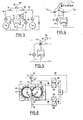
- An extruder 12 consisting of ten housing sections 11 is shown schematically in FIG. 1.
- the extruder 12 has a continuous longitudinal bore in the form of two circular cylinders which are partially established, as can be seen from FIG. 6.
- Two screws 14, 15 are arranged in the housing bore 13, the drive ends 16, 17 of which protrude from the left side of the extruder 12. They are driven there by a rotary drive, the two tightly intermeshing screws 14, 15 rotating in the same direction of rotation in the exemplary embodiment, see also FIG. 6 in this regard.
- the extruder is used in particular for the production of plastics, eg. B. by bulk polymerization.
- the conveying direction of the two screws 14, 15 in the extruder 12 shown in FIG. 1 is from left to right, so that the housing section 11a arranged in FIG. 1 at the left end has a schematically illustrated filling funnel 18 or filler neck for filling plastic or of monomers.
- a schematically illustrated filling funnel 18 or filler neck for filling plastic or of monomers.
- a separate circuit is provided for this purpose, which will be explained in the following. All other housing sections 11 are essentially the same, they are screwed together and form a continuous unit.
- the ninth housing section (second from the right in FIG.
- Fig. 1 the fluid or heat transfer medium circuits are shown with solid lines, the lines indicated by dashed lines are control lines.
- Each housing section 11 contains (in FIG. 1) an inlet 22 at the top and (in FIG. 1 on its underside) an outlet 23 for the heat transfer fluid.
- a servo-operated three-way valve 24 is arranged, each having two inlet sides 25, 26 and an outlet 27.
- the outlet side 27 of each three-way valve 24 is each connected to the inlet 22 of the housing section 11, while in each case one inlet 25 is connected to a fluid circuit 28 of higher temperature and each inlet 26 is connected to a second circuit 29 for a heat transfer fluid at a lower temperature.
- the fluidic circuit 28 is assumed to supply a heat carrier oil with a constant temperature of, for example, 200 ° C., while the fluidic circuit 29 supplies the same heat carrier fluid with the temperature of, for example, 50 ° C.
- a third fluid circuit 33 is provided, which is, for example, water-filled and can have a temperature of 15 °.
- the fluidics Circuit 33 contains a pump 34, a heat exchanger 35, and in addition to the three-way valve 31, a second three-way valve 36.
- the heat exchanger 35 is provided to keep the temperature of the water at exactly 15 °, for which purpose a line 37 is provided for a coolant, the can flow into the heat exchanger 35 in the direction of the arrow. Its flow is controlled by means of the valve 38, which can be controlled by the temperature of the water emerging from the heat exchanger 35 by means of a temperature sensor 39 immediately before the pump 34.
- the water with the constant temperature of 15 ° emerges from the pump 34 in the direction of arrow 40 and flows through the circuit 33 through the line 41 to the valve 31, from where a part of the liquid through the inlet 22 and through the housing section 11a passes through and returns to the heat exchanger 35.
- a portion of the water entering the valve 31 through the line 41 can be directed past the housing section 11a via the outlet 32 from the valve 31 and can be combined with the circuit 33 again on the inlet side or preferably on the outlet side of the heat exchanger 35.
- the fluidic circuit 33 for water contains a branch 42 so that the water of the fluidic circuit 33 can also be used via the valve 36 to cool the fluidic circuit 29 with the aid of the heat exchanger 43.
- the part of the water of the circuit 33 which does not pass through the valve 36 into the heat exchanger 43 is returned to the line 44 to the input side of the heat exchanger 35 or preferably to its output side.
- the valve 36 is influenced by a temperature sensor 45, which senses the temperature of the heat transfer fluid in the fluid circuit 29.
- the fluid circuit 29 for the heat transfer fluid for example 01, with the lower temperature, for example 50 °, contains, in addition to the already mentioned heat exchanger 43, a pump 46 and possibly a container 47 with an electrical heater 48, a line 49 leading from the container 47, which is connected to the inlets 26 of all three-way valves 24, and a return line 50 connected to the outlets 23 from the housing sections 11.
- a shunt 51 with a filter 52 is provided.
- the temperature in the container 47 is controlled via a control unit 54 so that it is exactly at 50 ° C. If the liquid arriving in the return line 50 is warmer than 50 °, it is cooled in the heat exchanger 43 to 50 °, which is done using the water of the circuit 33. In extreme cases, the container 47 can be heated to the desired temperature.
- the fluid circuit 28 for the heat transfer fluid with the higher temperature is in principle constructed in exactly the same way as the circuit 29, but without a heat exchanger. It therefore contains a container 55 with a heater 56 which is controlled by a control unit 57 which is connected to a temperature sensor 58.
- a pump 59 pumps the fluid in the direction of arrow 60 into a line 61 which is connected to the inlets 25 of all three-way valves 24.
- all the inlets 25 for the higher temperature fluid are parallel to each other, while all the inlets 26 for the lower temperature fluid are also parallel to each other.
- the fluidic circuit 28 contains a shunt 62 with a filter 63.
- a common return line 64 which can be divided into sections of different preferred temperatures with the aid of several valves 65.
- the middle valve 65 could be closed so that the two circuits are then separated from one another.
- a connection between the circuits 28 and 29 is also created on the output side.
- a bypass is provided, which can consist, for example, of two check valves 66 connected in parallel.
- valves 65 may be closed. It is also conceivable that the temperature returned is divided differently, for example that the outer housing sections have low temperature and the middle housing sections have high temperature. In this case, too, it would be possible to switch the lines in such a way that unnecessary mixing of fluid of different temperatures is avoided.
- the return line 50 is connected to the left half of the return line 64 and the return line 67 of the fluid circuit 28 to the right half of the return line 64.
- the valve 31 for the housing section 11 a and the valves 24 for the other housing bowl are each provided with a servo drive 68 which adjusts the valve position.
- the servo drives 68 are controlled via control lines 69 shown in dashed lines.
- each housing section 11 is independent of the other by mixing fluid two fluid circuits can be tempered at different temperatures, ie can be cooled, heated or stabilized at a certain temperature.
- the individual housing sections have their own circuits, each of which only as much higher or lower temperature thermal oil or fluid is metered in as is necessary to achieve the desired temperature in the housing section, whereby considerable energy savings can be achieved. If the volume of such a circuit is kept low, the system also works quickly.
- Fig. 2 shows another possibility of tempering with the help of differently constructed valves. Only one housing section 11 is shown and the circuits 28 and 29 are only shown in simplified form.
- the line 61 of the fluid circuit 28 in FIG. 1 leads into an inlet 70 of a servo valve 71, which can also be actuated by a servo drive 68, which is controlled via a control line 69. From the valve 71, the fluid of the circuit 28 can either be connected to the inlet 22 of the housing section to the left or to the return line 67 to the right.
- a line 74 which comes from a second servo valve 72, which is constructed in exactly the same way as the servo valve 71 in the circuit 28.
- the circuit for the housing section 11 can be additionally 1 has its own pump 75, add cooler fluid, while valve 71 can be used to add warmer fluid to the circuit for the housing section 11.
- the servo valves 71, 72 of the embodiment according to FIG. 2 could be driven by a common servo drive.
- the other casing shots have corresponding circuits of their own which are connected to the circuits 28 and 29 of the extremely temperature-controlled heating means via servo valves.
- the lines 61 and 49 of the circuits 28 and 29 each rest on a simple valve 76, both of which can be actuated by a common servo drive 68.
- only one of the two valves 76 need be opened at the same time.
- the outlet 23 has a branch 77, in which a pump 78 is arranged.
- a further simple valve 79 can be arranged behind the pump 78 and can also be controlled by a servo drive 68.
- part of the fluid leaving the housing section 11 can be returned, the temperature of this fluid generally being between the temperatures of the two circuits 28, 29. In this case, therefore, there is normally a mixture between the returned temperature and the lower or the higher temperature. This can lead to a very considerable energy saving, since less U1 needs to be heated or cooled.
- a part of the fluid leaving the outlet is likewise returned via a branch 77 and a pump 78, the returned part abutting the two inlets of two three-way valves 80.
- the left three-way valve 80 can be mixed with the fluid from the circuit 29, while one can be mixed with the right three-way valve 80 Mixing with the fluid from the circuit 28 can take place.
- both three-way valves can be driven by a common servo drive 68, since only one of the two three-way valves 80 need ever be open.
- the servo valves 80 according to FIG. 4 must be designed differently than those according to FIG. 1. In the embodiment according to FIG. 4, both valves 80 must be able to completely shut off a flow.
- FIG. 5 shows an embodiment similar to FIG. 4, in which a single four-way valve 81 with a servo drive 68 is used instead of the two three-way valves 80 according to FIG. 4.
- the four-way valve 81 has three inlets and one outlet.
- FIGS. 2 to 5 each represent only a single housing section 11, with a corresponding parallel connection of the hydraulic circuits taking place in an extruder 12 as in FIG. 1.
- the circulation pumps 78 of the shot circuits can have a common drive.
- Fig. 6 shows a cross section through a housing section 11, from which the arrangement of the two screws 14, 15 results in the housing bore 13. It can also be seen that heat medium channels are arranged in the longitudinal direction of the housing sections, which have the form of bores, and are connected on one side of the housing section to the inlet 22 and on the other side to the outlet 23. The inlet 22 and the outlet 23 are again only shown schematically. The three-way valve 24 according to FIG. 1 is also shown schematically. The arrangements of the temperature sensors can also be seen. A first temperature sensor 83 measures the temperature of the fluid in the inlet 22 of the housing section 11, while a second temperature sensor 84 senses the temperature at the outlet 23. A third temperature sensor 85 is arranged in the metal of the housing section 11, whereby it is guided between two heat medium channels 82 up to the housing opening 13.
- a fourth temperature sensor 86 is arranged in the gusset of the housing bore 13, from which it protrudes somewhat. It is arranged so that it cannot be touched by the threads 87 of the two screws 14, 15. However, it can be seen that it is touched by the plastic material so that it can measure its temperature.
- All temperature sensors are connected via control lines 88 to measuring transducers 89, which convert the signals supplied by the temperature sensors 83 to 86 into signals which can be processed further.
- the transducers 89 are connected to the actual control unit 91 via further control lines 90.
- This control unit 91 generates the signals for control of the servo drive 68 of the valve 24 are required.
- there are four temperature sensors so that the control unit 91 can process a total of four measured values. However, it is also possible for only one of the temperature sensors to be present or for the control unit 91 to make a selection from the measured values supplied.
- the energy balance of chemical reactions that are carried out in the extruder can also be calculated from the measured values and the flow rates of the individual shots, and conclusions can thus be drawn about the course of the reaction. It is also possible to produce plastics, starting from gaseous monomers, by replacing the filling funnels with gas inlet nozzles and guiding the drive ends 16, 17 of the screws 14, 15 gas-tight out of the extruder. Furthermore, the extruder, which is preferably designed to be pressure-tight, can also have pressure measuring points and sampling points for substance samples.
- Zone 8 had an attachment for the distillation of unpolymerized monomers, it had a temperature of 160 ° C.
- Zones 9 and 10 were heated to 145 ° C.
- the entire film is water-resistant on contact with water from the coating side, upon contact with water from the hydroxypropyl cellulose side the entire film dissolves completely.
- the filling zone was cooled to 20 ° C.
- zones 2 to 8 had a temperature of 105 ° C.
- zones 9 and 10 had a temperature of 145 ° C.
- the head of the reaction extruder was connected directly to a second extruder via a temperature-controlled melt line (cascade connection).
- the first zone of the second extruder had an attachment for the distillation of unpolymerized monomers. It had a temperature of 160 ° C. At a screw speed of 50 per minute and a current consumption of 40 A in the first extruder (reaction extruder), 0.15 kg of liquid per hour were distilled off from the distillation attachment of the second extruder (degassing and compounding extruder) ( approx. 99% raw turnover). In zones 2 to 4 of the Compoun In the extruder, the polymer melt was degassed at 160 ° C. in a vacuum of 1 torr.
- zones 5 to 7 5% stearic acid was mixed in at 145 ° C., then the stearic acid-containing polymer melt from zone 8 was applied at 145 ° C. from a slot die, as described in example 1, to the hydroxypropyl cellulose film containing soda.
- the filling zone was cooled to 20 ° C.
- zones 2 to 8 had a temperature of 120 ° C.
- zones 9 and 10 were heated to 145 ° C.
- the head of the reaction extruder was connected directly to a second extruder (cascade connection) via a melt line which could be tempered.
- the first zone of the second extruder had an attachment for distilling off unpolymerized monomers, they had a temperature of 170 ° C.
- a screw speed of 75 per minute and a current consumption of 30 A in the first extruder an average of 2.5 g of liquid per hour were drawn off from the distillation head of the second extruder (degassing and compounding extruder) (Raw turnover approx. 92%).
- the polymer melt was degassed at 170 ° C. in a vacuum of 1 torr.
- the composite film was approximately 150 ⁇ m thick in total.
- the stearic acid-containing side of the film (xthylacrylate-methacrylic acid copolymer) was approx. 50 ⁇ m thick and was water-resistant.
- the AMPD-containing side of the composite film (dimethylaminoethyl methahacrylate-vinyl propyl ether copolymer) was approx. 100 ⁇ m thick, and the entire film dissolved completely on contact with water from this side.
- thermoplastic materials and possibly also their processing can be carried out continuously with the aid of one or more extruders, in that the starting products or their mixture are metered continuously into the extruder. After interruptions to work, controlled heating is sufficient to melt the products solidified in the extruder so that production can continue.
Abstract
Description
Die Erfindung betrifft ein Verfahren zur Durchführung von chemischen Reaktionen, insbesondere zur Herstellung von Kunststoffen mit Hilfe von Extrudern sowie eine Anlage zur Durchführung dieses Verfahrens.The invention relates to a process for carrying out chemical reactions, in particular for the production of plastics with the aid of extruders, and to a plant for carrying out this process.
Extruder zur Verarbeitung von Kunststoffen benötigen im Betrieb relativ viel Energie, wobei die gewünschte genaue Temperaturführung häufig nicht möglich ist, selbst dann nicht, wenn die Extruder mit einer elektrischen Beheizung sowie mit Kühlschlangen für eine Kühlflüssigkeit ausgerüstet sind. Es ist auch schon vorgeschlagen worden, auf Extrudern thermoplastische Kunststoffe herzustellen, doch konnte sich diese Herstellungsart wegen der dabei aufgetretenen Schwierigkeiten bisher nicht durchsetzen. Es besteht aber ein Bedürfnis, flexibel einsetzbare und für verschiedene chemische Reaktionen verwendbare Reaktoren zur Verfügung zu haben, die für die Produktion von kleineren bis mittleren Produktmengen ausgelegt und mit geringem Aufwand umrüstbar sind.Extruders for processing plastics require a relatively large amount of energy during operation, and the desired precise temperature control is often not possible, even if the extruders are equipped with electrical heating and with cooling coils for a cooling liquid. It has also been proposed to produce thermoplastic materials on extruders, but this type of production has not been able to establish itself because of the difficulties encountered. However, there is a need for flexible use and for different chemical reactions to have available usable reactors that are designed for the production of small to medium product quantities and can be converted with little effort.
Dementsprechend liegt der Erfindung die Aufgabe zugrunde, ein Verfahren zur Durchführung von chemischen Reaktionen, insbesondere zur Herstellung von Kunststoffen mit Hilfe von Extrudern und hierzu geeignete Anlagen zu schaffen, die die gezielte Durchführung von verschiedenartigen chemischen Reaktionen, insbesondere die Herstellung von thermoplastischen Kunststoffen ermöglichen.Accordingly, the object of the invention is to provide a method for carrying out chemical reactions, in particular for the production of plastics with the aid of extruders, and systems suitable for this purpose which enable the targeted implementation of various chemical reactions, in particular the production of thermoplastic plastics.
Gemäß der Erfindung wird diese Aufgabe gelöst, indem eine sehr feinfühlige Temperaturführung für den Extruder geschaffen wird, die es ermöglicht, genaue Temperaturgrenzen einzuhalten. Hierzu wird die Transportstrecke des Extruders in verschiedene Temperaturzonen unterteilt, wobei die Temperatur in diesen Zonen individuell und unabhängig voneinander eingestellt wird. Es sind vorteilhafterweise mindestens fünf Temperaturzonen vorgesehen und in der Regel fünf bis fünfzehn und mehr Zonen, wobei ca. zehn Zonen pro Extruder bevorzugt sind. Die Anzahl der Zonen hängt im wesentlichen von der Temperaturempfindlichkeit einer durchzuführenden Reaktion ab. So kann der Transportstrecke im Extruder ein vorbestimmtes Temperaturprofil aufgezwungen werden, wodurch erreicht werden kann, daß beim Durchlaufen der Transportstrecke stattfindende chemische Reaktionen trotz der kontinuierlichen Förderung des Materials auf bestimmte Zonen lokalisiert werden. Dadurch ist es möglich, mit einer Anlage bzw. einem Extruder verschiedenartige chemische Reaktionen durchzuführen, wobei der Verfahrensablauf vorzugsweise vollautomatisch gesteuert wird. Hierzu können die einzelnen Verfahrensparameter für jede einzelne Reaktion in einem Programm vorgegeben werden, das mit Hilfe eines gleichartigen Extruders über einen Rechner erstellt wurde. Mit einer solchen Anlage können beispielsweise Produktionsmengen in der Größenordnung von 10 bis 20000 Jahrestonnen hergestellt werden.According to the invention, this object is achieved by creating a very sensitive temperature control for the extruder, which makes it possible to maintain precise temperature limits. For this purpose, the transport route of the extruder is divided into different temperature zones, the temperature in these zones being set individually and independently of one another. At least five temperature zones are advantageously provided and generally five to fifteen or more zones, with approximately ten zones per extruder being preferred. The number of zones essentially depends on the temperature sensitivity of a reaction to be carried out. Thus, a predetermined temperature profile can be imposed on the transport route in the extruder, whereby it can be achieved that chemical reactions taking place while passing through the transport route are localized to certain zones despite the continuous conveyance of the material. This makes it possible to carry out various chemical reactions with a plant or an extruder, the process sequence preferably being controlled fully automatically. For this purpose, the individual process parameters for each individual reaction can be specified in a program that was created using a similar extruder on a computer. With such a system, for example, production quantities in the order of 10 to 20,000 tons per year can be produced.
Bei einer bevorzugten Ausführungsform der Erfindung wird die Temperierung der Temperaturzonen ausschließlich mit Hilfe von Fluiden, insbesondere Flüssigkeiten, vorgenommen, die die Temperaturzonen durchströmen. Durch den Verzicht auf eine elektrische Beheizung kann der Extruder so explosionsgesichert ausgebildet werden, was bevorzugt ist. Außerdem kann die erfindungsgemäße Temperierung sehr feinfühlig durchgeführt werden, so daß Temperaturtoleranzen unter 1° C und sogar bis 0,1 C eingehalten werden können. Hierzu wird vorzugsweise eine Mischung von zwei Fluiden gleicher Art, aber unterschiedlicher Temperatur in der Weise vorgenommen, daß das in die Temperaturzone eintretende Fluid zur Aufrechterhaltung der gewünschten Temperatur Wärmemengen aufzunehmen oder abzugeben vermag, und zwar bei möglichst geringen Temperaturdifferenzen. So kann die Temperaturdifferenz A t zwischen Fluideintritt und Fluidaustritt der Temperaturzone in Abhängigkeit von der Empfindlichkeit der Reaktion unter 3°C und sogar unter 1° C gehalten werden. Die Flinkheit der Temperierung wird dadurch verbessert, daß die Mischung der Fluide unmittelbar vor der jeweiligen Temperaturzone erfolgt. Vorzugsweise weicht die Temperatur eines Fluids weniger als 5° C, vorzugsweise weniger als 3° C von der Solltemperatur der entsprechenden Temperaturzone ab, wogegen die Temperatur des anderen Fluids mit Vorteil weiterdavon entfernt liegen kann. Unterstützt werden kann dies noch dadurch, daß auch die Menge des die jeweilige Zone durchströmenden Fluids verändert wird. Auch kann die Verweildauer der Reaktionspartner in den einzelnen Temperaturzonen verschieden gehalten werden, wobei sie in Zonen mit hohem erforderlichem Wärmeaustausch vorzugweise geringer ist, wodurch erreicht wird, daß die pro Zeiteinheit benetzte Fläche zwischen dem zu behandelnden Material und dem Extruder vergrößert wird. Durch derartige Maßnahmen ist es möglich, chemische Reaktionen so genau zu steuern, daß beispielsweise bei Polymerisationsvorgängen ein Einfluß auf die Größe des Molekulargewichts der Polymeren genommen werden kann. So können beispielsweise durch Kühlung Reaktionen verhindert werden, bis eine ausreichende Durchmischung der Reaktionspartner erzielt ist und dann sehr schnell und kontrolliert gestartet werden, indem auf die anfängliche Kühlung eine schnelle Erhitzung auf die gewünschte Solltemperatur vorgenommen wird.In a preferred embodiment of the invention, the temperature zones are temperature-controlled exclusively with the aid of fluids, in particular liquids, which flow through the temperature zones. By dispensing with electrical heating, the extruder can be designed to be explosion-proof, which is preferred. In addition, the temperature control according to the invention can be carried out very sensitively, so that temperature tolerances below 1 ° C. and even up to 0.1 ° C. can be maintained. For this purpose, a mixture of two fluids of the same type but different temperatures is preferably carried out in such a way that the fluid entering the temperature zone is able to absorb or emit quantities of heat in order to maintain the desired temperature, with the smallest possible temperature differences. The temperature difference A t between fluid inlet and fluid outlet of the temperature zone can thus be kept below 3 ° C and even below 1 ° C depending on the sensitivity of the reaction. The agility of the temperature control is improved in that the fluids are mixed immediately before the respective temperature zone. The temperature of one fluid preferably deviates less than 5 ° C., preferably less than 3 ° C., from the target temperature of the corresponding temperature zone, whereas the temperature of the other fluid can advantageously be further away from it. This can be supported by the fact that the amount of fluid flowing through the respective zone is changed. The dwell time of the reactants in the individual temperature zones can also be kept different, it being preferably less in zones with a high heat exchange required, whereby the area wetted per unit of time between the material to be treated and the extruder is increased. Such measures make it possible to control chemical reactions so precisely that, for example during polymerization processes, the size of the molecular weight of the polymers can be influenced. For example, reactions can be prevented by cooling until sufficient mixing of the reactants is achieved and then started very quickly and in a controlled manner by rapid heating to the desired target temperature after the initial cooling.
Mit dem Extruder können auch unter hohem Druck oder unter Vakuum ablaufende Reaktionen durchgeführt werden, wenn der Extruder druckdicht ausgebildet ist. Außerdem sind die Schnecken des Extruders vorzugsweise mit verschiedenen Geschwindigkeiten antreibbar. Sollte wider Erwarten eine Reaktion zu heftig ablaufen, dann kann wiederum programmgesteuert durch Einlegen eines Schnellganges eine schnelle Austragung des Materials und somit eine Selbstreinigung des Extruders vorgenommen werden.Reactions can also be carried out with the extruder under high pressure or under vacuum if the extruder is designed to be pressure-tight. In addition, the screws of the extruder can preferably be driven at different speeds. If, contrary to expectations, a reaction is too violent, the material can be quickly discharged and the extruder can be self-cleaned by program control by inserting an overdrive.
Nach dem erfindungsgemäßen Verfahren können sowohl einphasige als auch mehrphasige Reaktionen durchgeführt werden. Dabei ist es möglich, Teile der Reaktionsmischung bzw. des Reaktionsmediums abzutrennen, bevor das gewünschte Produkt den Extruder verläßt. So können flüssige Bestandteile von Festbestandteilen durch an sich bekannte Siebeinrichtungen abgetrennt werden. Es ist aber auch möglich, flüchtige Bestandteile der Reaktionsmischung durch eine Destillation abzutrennen. Eine solche Destillation kann bei Umgebungsdruck durchgeführt werden. Es ist aber auch eine Vakuumdestillation möglich, wobei dann vorteilhafterweise, falls erforderlich, durch einen Druckstau an einer Stelle der Transportstrecke, die vor der Destillationsstelle liegt, verhindert wird, daß flüchtige Reaktionspartner aus dem noch nicht zur Reaktion gekommenen Reaktionsmedium abgezogen werden. Ein solcher Rückstau bzw. eine solche Drosselung kann auf verschiedene Art und Weise erzielt werden, beispielsweise, indem die Schnecken des Extruder mit nichtfördernden bzw. gegenfördernden Elementen versehen sind. Es ist auch möglich, zwei oder mehrere Extruder nacheinander zu schalten, wobei dann die Austragsdüse des einen Extruders die Drosseleinrichtung vor der im nachfolgenden Extruder angeordneten Destillationseinrichtung bildet. Im Gegensatz zu den üblichen Entgasungseinrichtungen, die lediglich zu einem kleinen Prozentsatz mitgeführte flüchtige Stoffe enfernen, können durch derartige Destillationseinrichtungen Lösungsmittel oder bei der Reaktion in stöchiometrischer Menge entstandene flüchtige Reaktionsprokukte abgezogen werden.Both single-phase and multi-phase reactions can be carried out by the process according to the invention. It is possible to separate parts of the reaction mixture or the reaction medium before the desired product leaves the extruder. For example, liquid components of solid components can be produced by sieving devices known per se be separated. However, it is also possible to remove volatile constituents of the reaction mixture by distillation. Such a distillation can be carried out at ambient pressure. However, vacuum distillation is also possible, in which case, if necessary, a pressure build-up at a point on the transport path which lies before the distillation point prevents volatile reactants from being withdrawn from the reaction medium which has not yet reacted. Such a backflow or throttling can be achieved in various ways, for example by providing the screws of the extruder with non-conveying or counter-conveying elements. It is also possible to connect two or more extruders in succession, in which case the discharge nozzle of one extruder then forms the throttle device upstream of the distillation device arranged in the subsequent extruder. In contrast to the conventional degassing devices, which only remove a small percentage of volatiles carried along, such distillation devices can be used to draw off solvents or volatile reaction products formed during the reaction in a stoichiometric amount.
Weiterhin können dem die Transportstrecke durchlaufenden Reaktionsmedium in jeder Zone weitere Reaktionspartner zugefügt werden, z. B. Starter, Beschleuniger oder solche Reaktionspartner, die anteilweise zugegeben werden. Hierzu können im Extruder geeignete Zudosierungsöffnungen vorgesehen sein. Durch geeignete Kombination dieser zahlreichen Variationsmöglichkeiten ergibt sich die vielseitige Einsatzmöglichkeit des erfindungsgemäßen Verfahrens und der hierzu vorgesehenen Anlage zur Durchführung von unterschiedlichen chemischen Verfahren, ohne daß wesentliche Umbauten am Extruder vorzunehmen sind. In der Regel sind nicht einmal Veränderungen an der bzw. den Schnecken erforderlich, solche können jedoch durch Austausch der einzelnen Schneckenelemente ohne Schwierigkeiten vorgenommen werden. Unabhängig davon können der Zugabebeginn, die Menge und das Mischungsverhältnis der Reaktionspartner, das Temperaturprofil der Transportstrecke, der Druck und/oder die Schneckendrehzahl in Abhängigkeit von der gewünschten Reaktion programmgesteuert vorgegeben werden, wodurch eine große Variationsbreite von durchführbaren Reaktionen erhalten wird. So ist es mit besonderem Vorteil möglich, die variablen Daten der Arbeits- bzw. Reaktionsbedingungen auf einer Datenbank zu speichern und in Abhängigkeit von den gewünschten Eigenschaften der Endprodukte abzurufen, wodurch sich eine universelle Einsatzmöglichkeit ergibt. Demgegenüber sind die bisher bekannten, zur Durchführung von chemischen Reaktionen bestimmten Extruder auf ganz bestimmte Reaktionen ausgelegt und daher in ihrer Einsatzmöglichkeit stark beschränkt.Furthermore, further reaction partners can be added to the reaction medium passing through the transport route in each zone, e.g. B. starters, accelerators or those reactants which are added in part. For this purpose, suitable metering openings can be provided in the extruder. A suitable combination of these numerous possible variations results in the versatility of the method according to the invention and the related purpose provided system for carrying out different chemical processes without major modifications to the extruder. As a rule, it is not even necessary to make changes to the screw or screws, but these can be made without difficulty by exchanging the individual screw elements. Regardless of this, the start of addition, the amount and the mixing ratio of the reactants, the temperature profile of the transport route, the pressure and / or the screw speed can be predetermined in a program-controlled manner as a function of the desired reaction, as a result of which a wide range of reactions which can be carried out is obtained. It is particularly advantageous to store the variable data of the working or reaction conditions in a database and to call them up depending on the desired properties of the end products, which results in a universal application. In contrast, the previously known extruders intended for carrying out chemical reactions are designed for very specific reactions and are therefore very limited in their possible uses.
Die erfindungsgemäße Anlage zur Durchführung des Verfahrens weist mit Vorteil mindestens einen Ein- oder MehrschneckenExtruder mit jeweils mindestens fünf Gehäuseschüssen auf, die jeweils für sich, d. h. unabhängig voneinander temperierbar sind. Die einzelnen Gehäuseschüsse entsprechen somit im wesentlichen den Temperaturzonen und sind jeweils mit eigenen Tepmerierungseinrichtungen ausgerüstet.The system according to the invention for carrying out the method advantageously has at least one single-screw or multi-screw extruder, each with at least five housing sections, each for itself, ie. H. are independently temperature-controllable. The individual housing sections thus essentially correspond to the temperature zones and are each equipped with their own tepmerization devices.
Der Extruder kann in seiner Größe innerhalb von weiten Grenzen variieren, so z. B. einen Bohrungsdurchmesser von 30 bis 120 mm oder mehr haben, wobei die kleineren mehr für Versuchszwecke und die größeren für Produktionszwecke geeignet sind. In der Regel entspricht die Länge eines Schusses etwa dem fünffachen Bohrungsdurchmesser, wobei hier jedoch innerhalb weiter Grenzen variiert werden kann. Normalerweise sind zwischen 5 und 15 Schüsse vorgesehen. Die Extruder können feste, flüssige oder auch gasförmige Ausgangsstoffe verarbeiten. Es können auch zwei oder mehr Extruder kaskadenförmig hintereinander geschaltet sein, insbesondere, wenn flüchtige Monomere verarbeitet werden oder flüchtige Nebenprodukte entstehen.The size of the extruder can vary within wide limits. B. have a bore diameter of 30 to 120 mm or more, the smaller ones are more suitable for experimental purposes and the larger ones for production purposes. As a rule, the length of a shot corresponds approximately five times the diameter of the bore, but can be varied within wide limits. There are usually between 5 and 15 shots. The extruders can process solid, liquid or gaseous raw materials. Two or more extruders can also be cascaded in series, in particular if volatile monomers are processed or volatile by-products are formed.
Die Erfindung schlägt weiterhin vor, daß zwei Schnecken in gleicher Drehrichtung rotieren können. Dies ist eine Maßnahme, die aufgrund der Möglichkeit des dichten Kämmens das gute Durchmischen von Kunststoffen wesentlich verbessert.The invention further proposes that two screws can rotate in the same direction of rotation. This is a measure which, due to the possibility of tight combing, significantly improves the thorough mixing of plastics.
In Weiterbildung kann vorgesehen sein, daß die Schnecken dreigängig sind. Es hat sich herausgestellt, daß dies die optimale Anzahl von Gängen bei Extruderschnecken ist.In a further development it can be provided that the screws are three-course. It has been found that this is the optimal number of extruder screw threads.
Um auch die Verweilzeit der Kunststoffe in den einzelnen Temperaturbereichen verändern zu können, kann nach einem weiteren Merkmal der Erfindung vorgesehen sein, daß die Schnecken eine sich über ihre Länge ändernde Steigung aufweisen.In order to also be able to change the residence time of the plastics in the individual temperature ranges, it can be provided according to a further feature of the invention that the screws have an incline that changes over their length.
Erfindungsgemäß kann weiterhin vorgesehen sein, daß mindestens ein, vorzugsweise jeder Gehäuseschuß eine zusätzliche öffnung aufweist. Damit wird die Möglichkeit gegeben, einen weiteren Zusatzstoff in den Extruder an einer bestimmten Stelle einzubringen, Druckmesseinrichtungen anzuschließen und/oder Teile des Reaktionsmediums abzutrennen.According to the invention it can further be provided that at least one, preferably each housing section has an additional opening. This gives the possibility of introducing a further additive into the extruder at a specific point, connecting pressure measuring devices and / or separating parts of the reaction medium.
Es kann ebenfalls vorgesehen sein, daß mindestens ein Gehäuseschuß eine Entgasungsöffnung aufweist. Hier können gasförmige Stoffe abgezogen werden, falls dies entsprechend den gewünschten Eigenschaften erwünscht ist. Mit besonderem Vorteil weist die Anlage noch mindestens eine Destillationseinrichtung, vorzugsweise eine Vakuumdestillationseinrichtung, auf, die an eine Öffnung eines Gehäuseschusses angeschlossen ist, um größere Mengen an flüchtigen Stoffen abtrennen zu können. Der für die Destillation vorgesehene Druck bzw. Unterdruck kann einstellbar gehalten werden, wozu der Extruder vor der Destillationseinrichtung vorzugsweise eine Drossel aufweist. Auch wird die Temperatur in der Destillationszone mit Vorteil höher gehalten als in den übrigen Zonen, um den Dampfdruck der flüchtigen Stoffe zu erhöhen.It can also be provided that at least one housing section has a degassing opening. Here gaseous substances can be withdrawn, if this corresponds to the ge desired properties is desired. With particular advantage, the system also has at least one distillation device, preferably a vacuum distillation device, which is connected to an opening in a housing section in order to be able to separate larger amounts of volatile substances. The pressure or negative pressure provided for the distillation can be kept adjustable, for which purpose the extruder preferably has a throttle in front of the distillation device. The temperature in the distillation zone is also advantageously kept higher than in the other zones in order to increase the vapor pressure of the volatile substances.
Um ein möglichst exaktes Temperaturprofil des Extruders zu ermöglichen, kann, wie bereits erwähnt, zur Temperierung ein Wärmeträgerfluid vorgesehen sein, dessen Temperatur durch Mischung aus Fluid mit zwei unterschiedlichen Temperaturen veränderbar ist. Die beiden unterschiedlichen Temperaturen, aus denen die gewünschte Temperatur zusammengemischt wird, sind so gewählt, daß die Solltemperatur immer bei oder zwischen diesen beiden Werten liegt. Als Wärmeträgerfluid wird vorzugsweise eine Flüssigkeit verwendet, die bei beiden Temparaturen noch eine ausreichende Viskosität und Stabilität besitzt. Hier eignen sich Thermoöle, die beispielsweise im Bereich von 50° bis 200° C oder mehr einsetzbar sind, für niedrige Temperaturbereiche auch Wasser.In order to enable the temperature profile of the extruder to be as precise as possible, as already mentioned, a heat transfer fluid can be provided for temperature control, the temperature of which can be changed by mixing fluid with two different temperatures. The two different temperatures from which the desired temperature is mixed are selected so that the target temperature is always at or between these two values. A liquid is preferably used as the heat transfer fluid which still has sufficient viscosity and stability at both temperatures. Thermal oils that can be used in the range from 50 ° to 200 ° C. or more, for example, and water for low temperature ranges are suitable here.
Bei der Temperierung kann mit Hilfe einer entsprechenden Steuerung vorgesehen sein, daß die Temperaturdifferenz zwischen dem Fluid am Einlaß und dem Fluid am Auslaß einen bestimmten Wert nicht überschreitet, so daß innerhalb des Gehäuseschusses die Temperaturunterschiede nicht zu groß werden. Die Erfindung schlägt ebenfalls vor, daß zusätzlich oder alternativ zur Veränderung der Temperatur des Fluides die Menge des den Gehäuseschuß durchströmenden Fluids veränderbar ist. Dies ist insbesondere dann von Nutzen, wenn man nur eine geringe Temperaturdifferenz zwischen Einlaß- und Auslaßfluid zuläßt, um innerhalb des Gehäuseschusses keine zu hohen Temperaturdifferenzen auftreten zu lassen. In diesem Falle kann man die Menge des durchströmenden Fluids vergrößern.In the case of the temperature control, it can be provided with the aid of a corresponding control that the temperature difference between the fluid at the inlet and the fluid at the outlet does not exceed a certain value, so that the temperature differences within the housing section do not become too great. The invention also proposes that, in addition or as an alternative to changing the temperature of the fluid, the amount of the fluid flowing through the housing section can be changed. This is particularly useful if you allows only a small temperature difference between the inlet and outlet fluid in order not to allow excessive temperature differences to occur within the housing section. In this case, the amount of fluid flowing through can be increased.
Um eine besonders exakte und schnelle Regelung der Temperatur zu ermöglichen, kann erfindungsgemäß vorgesehen sein, daß die Mischung des Fluids unmittelbar vor dem Eintritt des Fluids in den Gehäuseschuß erfolgt.In order to enable a particularly precise and rapid regulation of the temperature, it can be provided according to the invention that the mixing of the fluid takes place immediately before the fluid enters the housing section.
Zur Herstellung der Mischung von Fluid aus zwei Temperaturen kann erfindungsgemäß für jeden Gehäuseschuß mindestens ein Servoventil mit einem vorzugsweise kontinuierlich veränderbaren Mischungsverhältnis vorgesehen sein. Dabei sind unterschiedliche Ventilarten verwendbar. Um das richtige Mischungsverhältnis einzustellen, kann in Weiterbildung vorgesehen sein, daß das Servoventil von mindestens einem Temperaturfühler über eine elektronische Steuerung zur Regelung der Temperatur in dem Gehäuseschuß beeinflußbar ist. Es gibt mehrere Möglichkeiten der Anbringung des Temperaturfühlers, wobei es selbstverständlich auch möglich ist, daß man mehr als einen Temperaturfühler gleichzeitig vorsieht. Dabei kann es entweder möglich sein, zwischen den einzelnen Temperaturfühlern umzuschalten, oder aber eine Kombination von Meßwerten mehrerer Temperaturfühler als Eingangsgröße für die elektronische Steuerung zu verwenden.To produce the mixture of fluid from two temperatures, at least one servo valve with a preferably continuously variable mixing ratio can be provided for each housing section according to the invention. Different types of valves can be used. In order to set the correct mixing ratio, it can be provided in a further development that the servo valve can be influenced by at least one temperature sensor via an electronic control for regulating the temperature in the housing section. There are several ways of attaching the temperature sensor, although it is of course also possible to provide more than one temperature sensor at the same time. It can either be possible to switch between the individual temperature sensors or a combination of measured values from several temperature sensors can be used as an input variable for the electronic control.
Die Erfindung schlägt vor, daß ein Temperaturfühler zur Messung der Temperatur des Gehäuseschusses, vorzugsweise in geringem Abstand von der von den Schnecken durchsetzten Innenbohrung angeordnet ist. Da die Gehäuseschüsseaus Metall bestehen, kann auf, diese Art eine recht gute Abfühlung der Temperatur vorgenommen werden. Es ist jedoch ebenfalls mit Vorteil möglich, daß ein Temperaturfühler zur Messung der Fluidtemperatur am Einlaß in dem Gehäuseschuß angeordnet ist. Diese Möglichkeit ist insbesondere dann wertvoll, wenn man, wie von der Erfindung ebenfalls vorgeschlagen wird, einen Temperaturfühler zu Messung der Fluidtemperatur am Auslaß aus dem Gehäuseschuß anordnet. Mit Hilfe dieser beiden Temperaturfühler läßt sich dafür sorgen, daß die Temperaturdifferenz zwischen dem Einlaß und dem Auslaß aus dem Gehäuseschuß nicht zu groß wird. Darüber hinaus läßt sich aus der Differenz der Meßwerte feststellen, ob in diesem Gehäuseschuß eine endotherme oder eine exotherme Reaktion vorliegt, oder ob sich die Temperatur in diesem Gehäuseschuß selbst stabilisiert. In diesem Fall wäre beispielsweise in dem entsprechenden Gehäuseschuß weder eine Kühlung noch eine Erwärmung erforderlich.The invention proposes that a temperature sensor for measuring the temperature of the housing section is arranged, preferably at a short distance from the inner bore penetrated by the screws. Since the housing bowls are made of metal, this type of temperature can be sensed quite well. However, it is also with Advantage possible that a temperature sensor for measuring the fluid temperature is arranged at the inlet in the housing section. This possibility is particularly valuable if, as is also proposed by the invention, a temperature sensor for measuring the fluid temperature at the outlet from the housing section is arranged. With the help of these two temperature sensors, it can be ensured that the temperature difference between the inlet and the outlet from the housing section does not become too great. In addition, it can be determined from the difference in the measured values whether there is an endothermic or an exothermic reaction in this housing section or whether the temperature in this housing section stabilizes itself. In this case, neither cooling nor heating would be required in the corresponding housing section, for example.
Eine weitere besondere günstige Möglichkeit der Anordnung eines Temperaturfühlers ist dann gegeben, wenn dieser zur Messung der Temperatur der Schmelze in dem Extruder angeordnet ist. Da die Gänge der Schnecke mit geringem Abstand von der Gehäusewandung vorbeistreichen, ist es immerhin doch möglich, beispielsweise in den zwischen den beiden Schnecken gebildeten Zwickel einen Temperaturfühler soweit in das Innere des Gehäuse hineinragen zu lassen, daß er von der Schmelze, aber nicht von den Schnecken berührt wird. Dieser Temperaturfühler mißt dann exakt die Temperatur des im Extruderschuß vorhandenen Kunststoffes, wobei auch hier aus den Temperaturunterschieden zwischen dem Kunststoff und dem Gehäuse 'Rückschlüsse gezogen werden können.Another particularly favorable possibility of arranging a temperature sensor is provided if it is arranged in the extruder for measuring the temperature of the melt. Since the threads of the screw pass a short distance from the housing wall, it is still possible, for example, to let a temperature sensor protrude into the interior of the housing, for example in the gusset formed between the two screws, so that it is from the melt, but not from the Snails is touched. This temperature sensor then measures exactly the temperature of the plastic present in the extruder section, and here too, conclusions can be drawn from the temperature differences between the plastic and the housing.
Die Art des von der Erfindung vorgeschlagenen Servoventils läßt sich auf unterschiedliche Möglichkeiten verwirklichen. Eine besonders günstige Möglichkeit ist dann gegeben, wenn das Servoventil ein Dreiwegeventil mit zwei Einläßen und einem Auslaß ist, wobei an jedem Einlaß je eine Abzweigung eines Fluidkreislaufs anliegt, von denen beide unterschiedlich hohe Temperaturen aufweisen. Dies bedeutet, daß an dem einen Eingang des Dreiwegeventils ein Fluidkreislauf mit der niedrigst nötigen Temperatur anliegt, während am anderen Einlaß ein Fluidkreislauf mit der höchsten notwendigen Temperatur anliegt. Aus beiden Temperaturwerten kann je nach Stellung des Servoventils eine Auslaßtemperatur gemischt werden, die zwischen den beiden Extremwerten liegt und im Schuß die gewünschte Temperatur ergibt. Besonders günstig ist es dabei, wenn beide Kreisläufe je einen Nebenschluß und eine Pumpe aufweisen. Es kann beispielsweise nötig sein, den gesamten Extruder nur zu kühlen, so daß plötzlich alle Ventile nur das Fluid mit der niedrigeren Temperatur durchlassen. Damit nicht für diesen Betriebszustand ein eigener Fühler vorhanden sein muß, der die Pumpe des Kreislaufs mit der höheren Temperatur abschaltet, ist der Nebenschluß vorgesehen. Dies macht es auch möglich, daß die Pumpe mit einer relativ großen Förderleistung arbeitet, so daß an den Einlässen der Ventile aller Gehäuseschüsse die gleichen Druckverhältnisse und damit die gleichen Regelungscharakteristika des jeweiligen Ventils vorliegen.The type of servo valve proposed by the invention can be implemented in different ways. A particularly favorable possibility is given if the servo valve is a three-way valve with two inlets and one outlet, with one branch at each inlet of a fluid circuit, both of which have different temperatures. This means that a fluid circuit with the lowest necessary temperature is present at one input of the three-way valve, while a fluid circuit with the highest necessary temperature is present at the other inlet. Depending on the position of the servo valve, an outlet temperature can be mixed from both temperature values, which lies between the two extreme values and results in the desired temperature in the shot. It is particularly advantageous if both circuits each have a shunt and a pump. For example, it may be necessary to only cool the entire extruder, so that suddenly all the valves only let the fluid through at the lower temperature. The shunt is provided so that there is no need for a separate sensor for this operating state, which switches off the pump of the circuit with the higher temperature. This also makes it possible for the pump to work with a relatively large delivery rate, so that the same pressure conditions and thus the same control characteristics of the respective valve are present at the inlets of the valves of all housing sections.
Die Erfindung schlägt weiterhin vor, daß mindestens ein, vorzugsweise beide Kreisläufe eine vorzugsweise elektrische Beheizung mit einer Temperaturregelung und der Kreislauf für die niedrigere Temperatur einen Wärmetauscher zur Abkühlung aufweisen können. Die Beheizungen bzw. die Kühlung sind erforderlich, damit gewährleistet ist, daß die beiden Fluidkreisläufe tatsächlich Fluid mit einer festen vorbestimmten Temperatur liefern, so daß damit dann eine Mischung auf exakte Temperatur durchgeführt werden kann.The invention further proposes that at least one, preferably both circuits may have a preferably electrical heating with a temperature control and the circuit for the lower temperature may have a heat exchanger for cooling. The heating or cooling is necessary to ensure that the two fluid circuits actually deliver fluid at a fixed predetermined temperature, so that it can then be used to mix to the exact temperature.
Die Erfindung schlägt weiterhin vor, daß die Auslässe mehrerer Gehäuseschüsse mit Ausnahme der ersten, der vorzugsweise wassergekühlt ist, in gemeinsame Rückleitungen münden, die ggf. durch Ventile in zwei Teile unterschiedlich bevorzugter Temperatur aufteilbar sind, wobei der Teil höherer bzw. tieferer Temperatur mit dem Rücklauf des Kreislaufs mit höherer bzw. tieferer Temperatur verbunden ist. Dies macht es beispielsweise möglich, falls bei dem einzustellenden Wärmeprofil tätsächlich zwei Teile mit deutlich getrennter Temperatur vorgesehen sind, daß der Kreislauf für das U1 mit höherer Temperatur bevorzugt von 01 mit höherer Temperatur beliefert wird. Zum Ausgleich der Rücklaufmengen im Verhältnis zu den Vorlaufmengen sind vorzugsweise Querverbindungen vorhanden.The invention further proposes that the outlets of a plurality of housing sections with the exception of the first, which is preferred is water-cooled, lead into common return lines, which can optionally be divided by valves into two parts of different preferred temperatures, the part of higher or lower temperature being connected to the return of the circuit with higher or lower temperature. This makes it possible, for example, if two parts with a clearly separated temperature are actually provided in the heat profile to be set, so that the circuit for the U1 with a higher temperature is preferably supplied from 01 with a higher temperature. To compensate for the return quantities in relation to the preliminary quantities, cross connections are preferably available.
Die Erfindung schlägt in Weiterbildung vor, daß zur Temperierung des Gehäuseschusses mindestens ein Teil des den Gehäuseschuß verlassenden Fluids rückführbar ist. Zur Rückführung kann eine Pumpe vorgesehen sein, wobei die Rückführung ebenfalls wieder mit Hilfe eines Ventiles gesteuert werden kann. Dieser von der Erfindung vorgeschlagenen Maßnahme liegt der Gedanke zugrunde, daß im Regelfall die Temperatur des den Gehäuseschuß verlassenden Fluids zwischen den beiden Extremtemperaturen liegt, so daß entweder eine Mischung des zurückgeführten Fluids mit dem Fluid niedrigerer Temperatur oder mit dem Fluid höherer Temperatur zur Temperierung des Gehäuseschusses ausreicht, was zu einer deutlichen Energieersparnis führt. Diese Möglichkeit der Rückführung läßt sich auch mit einfacheren Ventilen durchführen, z. B.durch zwei oder drei Zweiwegventile pro Schuß. Ebenfalls durchführen läßt sich diese Art der Temperierung mit zwei Dreiwegventilen oder einem Vierwegventil. Ebenfalls denkbar ist es, eine gesteuerte Pumpe vorzusehen, so daß das Mischungsverhältnis durch die Förderleistung der Pumpe reguliert wird. Für den Extremfall, d. h. beispielsweise eine vollständige Kühlung aller Temperaturschüsse,kann auch hier vorgesehen sein, daß die Pumpe ausschaltbar ist.In a further development, the invention proposes that at least a portion of the fluid leaving the housing section be traceable for the temperature control of the housing section. A pump can be provided for the return, wherein the return can also be controlled again with the aid of a valve. This measure proposed by the invention is based on the idea that, as a rule, the temperature of the fluid leaving the housing section lies between the two extreme temperatures, so that either a mixture of the returned fluid with the fluid at a lower temperature or with the fluid at a higher temperature for temperature control of the housing section sufficient, which leads to significant energy savings. This possibility of recycling can also be carried out with simpler valves, e.g. B. by two or three two-way valves per shot. This type of temperature control can also be carried out with two three-way valves or one four-way valve. It is also conceivable to provide a controlled pump so that the mixing ratio is regulated by the delivery rate of the pump. In the extreme case, d. H. For example, complete cooling of all temperature shots can also be provided here that the pump can be switched off.
Zur Energieeinsparung wird weiterhin auch bei anderen Nebenschlüssen oder Bypass-Einrichtungen darauf geachtet, daß RUck- bzw. Nebenströme mit den Extremtemperaturen mit auf gleichem Temperaturniveau stehenden Strömen vereinigt werden, also in der Regel an der Ausgangsseite der Kühl- bzw. Heizeinrichtungen, da auf diese Weise der Wärmeaustausch auf kleinere Flüssigkeitsvolumina beschränkt werden kann, bei etwas höherer Temperaturdifferenz, was günstiger ist, als umgekehrt.To save energy, care is also taken with other shunts or bypass devices to ensure that reverse or secondary flows are combined with the extreme temperatures with currents at the same temperature level, i.e. generally on the outlet side of the cooling or heating devices, since these Way the heat exchange can be limited to smaller volumes of liquid, at a slightly higher temperature difference, which is cheaper than vice versa.
Die Mischung der Reaktionspartner kann in der bzw. den ersten Zonen des Extruders erfolgen. Vorzugsweise werden mindestens zwei Reaktionspartner vor Eintritt in den Extruder ggf. unter Kühlung miteinander vermischt. Weiterhin ist vorzugsweise mindestens eine Dosiereinrichtung mit veränderbarer Dosiermenge vorgesehen, wobei insbesondere mindestens zwei Dosierpumpen mit einstellbarem Hub vorgesehen sind, die einen gemeinsamen regelbaren Antrieb besitzen. Diese Variablen können ebenfalls programmgesteuert veränderbar sein, ebenso wie ein etwaiger Aufgabedruck, mit dem die Ausgangsprodukte in den Extrudern eingepumpt werden.The reactants can be mixed in the first zone or zones of the extruder. Preferably, at least two reactants are mixed with one another, possibly with cooling, before entering the extruder. Furthermore, at least one metering device with a variable metering quantity is preferably provided, in particular at least two metering pumps with an adjustable stroke being provided, which have a common, controllable drive. These variables can also be programmatically changeable, as well as a possible feed pressure with which the starting products are pumped into the extruders.
Das erfindungsgemäße Verfahren und die erfindungsgemäße Anlage eignen sich besonders zur Herstellung von thermoplastischen Kunststoffen, insbesondere solchen, wie sie zur Herstellung von Verbundfolien bzw. Verbundplatten geeignet sind, die von einer Seite her wasserfest und von der anderen Seite her wasserlöslich sind. Derartige Folien bzw. Platten sind beispielsweise in den europäischen Offenlegungsschriften 32 244, 69 296 und 78 553 des Anmelders beschrieben. Dabei handelt es sich um Verbundmaterialien aus mindestens zwei Schichten, wobei eine Schicht in Wasser an sich unlöslich, aber in saurem oder basischem Medium löslich ist und die andere Schicht in Wasser löslich bzw. lösbar Ist und einen sauren oder basischen Lösungsvermittler für die in Wasser an sich unlösliche Schicht enthält. Die Herstellung der thermoplastischen Kunststoffe und ihre Verarbeitung kann dabei in parallel und/oder hintereinander geschalteten Extrudern erfolgen, wobei die bei der Herstellung freiwerdende Reaktionswärme auch zum Aufschmelzen von Ausgangsmaterialien bzw. Endprodukten in demselben oder einem anderen Extruder wieder eingesetzt werden kann.The method according to the invention and the system according to the invention are particularly suitable for the production of thermoplastics, in particular those such as are suitable for the production of composite films or composite panels which are waterproof on one side and water-soluble on the other side. Such films or plates are described, for example, in the applicant's European laid-open documents 32 244, 69 296 and 78 553. These are composite materials made up of at least two layers, one layer being insoluble in water, but is soluble in acidic or basic medium and the other layer is soluble or soluble in water and contains an acidic or basic solubilizer for the water-insoluble layer. The thermoplastic materials can be produced and processed in extruders connected in parallel and / or in series, the heat of reaction released during the production also being able to be used again for melting starting materials or end products in the same or another extruder.
Weitere Merkmale, Einzelheiten und Vorzüge der Erfindung ergeben sich aus der folgenden Beschreibung bevorzugte Ausführungsformen der Erfindung sowie anhand der Zeichnung. Hierbei zeigen:
- Fig. 1 eine schematische Darstellung eines Extruders mit Fluidkreisläufen zur unabhängigen Steuerung der Temperatur jedes Gehäuseschusses;
- Fig. 2 eine andere Möglichkeit der genauen Temperierung eines Gehäuseschusses;
- Fig. 3 eine dritte Ausführungsform der Temperierung eines Gehäuseschusses;
- Fig. 4 eine weitere Möglichkeit der Temperierung mit Hilfe zweier Dreiwegventile;
- Fig. 5 eine Möglichkeit der Temperierung mittels eines Vierwegventils;
- Fig. 6 schematisch einen Querschnitt durch den Extruder mit schematisch angegebener Anordnung der Temperaturfühler;
- Figure 1 is a schematic representation of an extruder with fluid circuits for independent control of the temperature of each housing section.
- 2 shows another possibility for the exact temperature control of a housing section;
- 3 shows a third embodiment of the temperature control of a housing section;
- 4 shows a further possibility of tempering with the aid of two three-way valves;
- 5 shows a possibility of tempering by means of a four-way valve;
- 6 schematically shows a cross section through the extruder with a schematically indicated arrangement of the temperature sensors;
In Fig. 1 ist schematisch ein aus zehn Gehäuseschüssen 11 bestehender Extruder 12 dargestellt. Der Extruder 12 besitzt eine durchgehende Längsbohrung in der Form zweier sich teilweise durchsetzender Kreiszylinder, wie aus Fig. 6 ersichtlich ist. In der Gehäusebohrung 13 sind zwei Schnecken 14, 15 angeordnet, deren Antriebsenden 16, 17 aus der linken Seite des Extruders 12 herausragen. Sie werden dort von einem Drehantrieb angetrieben, wobei im Ausführungsbeispiel die beiden dichtkämmenden Schnecken 14, 15 im gleichen Drehsinn rotieren, siehe hierzu auch Fig. 6. Der Extruder dient insbesondere zur Herstellung von Kunststoffen, z. B. durch SubstanzPolymerisation.An
Die Förderrichtung der beiden Schnecken 14, 15 bei dem in Fig. 1 dargestellten Extruder 12 ist von links nach rechts, so daß der in Fig. 1 am linken Ende angeordnete Gehäuseschuß 11a einen schematisch dargestellten Einfülltrichter 18 bzw. Einfüllstutzen zum Einfüllen von Kunststoff bzw. von Monomeren aufweist. Es können selbstverständlich auch zwei oder mehrere Einfüllöffnungen zum Einfüllen verschiedener Komponenten vorhanden sein. Wenn in dem in Förderrichtung am Anfang liegenden Gehäuseschuß 11a keine Reaktion, sondern eine Vermischung stattfinden und eine Reaktion verhindert werden soll, erfolgt in diesem Gehäuseschuß nur eine Kühlung. Zu diesem Zweck ist ein eigener Kreislauf vorgesehen, der im folgenden noch erläutert wird. Alle übrigen Gehäuseschüsse 11 sind im wesentlichen gleich ausgebildet, sie sind miteinander verschraubt und bilden eine durchgehende Einheit. Der neunte Gehäuseschuß (zweiter von rechts in Fig. 1) steht mit einer Destillationseinrichtung 19 in Verbindung, an die ein Unterdruck angelegt werden kann, so daß diesem zweitletzten Gehäuseschuß flüchtige Bestandteile entzogen werden können. Eine Drosseleinrichtung 20 im achten Gehäuseschuß verhindert, daß durch den Unterdruck noch nicht umgesetzte Monomere aus den vorhergehenden Schüssen abgezogen werden. Am rechten Ende des Extruders 12 inst eine Austrittsdüse 21 für das Endprodukt angeordnet.The conveying direction of the two
In Fig. 1 sind die Fluid- bzw. Wärmeträgermittelkreisläufe mit ausgezogenen Linien dargestellt, wobei die gestrichelt angedeuteten Leitungen Steuerleitungen sind.In Fig. 1, the fluid or heat transfer medium circuits are shown with solid lines, the lines indicated by dashed lines are control lines.
Jeder Gehäuseschuß 11 enthält(in Fig. 1) oben einen Einlaß 22 und (in Fig. 1 an seiner Unterseite)einen Auslaß 23 für das Wärmeträgerfluid. Unmittelbar vor dem Einlaß 22 jedes Gehäuseschußes 11 ist ein servobetätigtes Dreiwegeventil 24 angeordnet, das jeweils zwei Einlaßseiten 25, 26 und einen Auslaß 27 aufweist. Die Auslaßseite 27 jedes Dreiwegeventils 24 ist jeweils mit dem Einlaß 22 des Gehäuseschusses 11 verbunden, während jeweils ein Einlaß 25 mit einem Fluidikkreislauf 28 höherer Temperatur und jeweils der Einlaß 26 mit einem zweiten Fluidikkreislauf 29 für ein Wärmeträgerfluid mit niedrigerer Temperatur verbunden ist. Dies gilt für alle Gehäuseschüsse 11 mit Ausnahme des in Transportrichtung ersten Gehäuseschußes 11 a, bei dem der Einlaß 22 zwar auch mit dem Auslaß 30 eines Dreiwegeventils 31 verbunden ist, das jedoch einen zweiten Auslaß 32 aufweist.Each
Von dem Fluidikkreislauf 28 sei angenommen, daß er ein Wärträgeröl mit einer konstanten Temperatur von beispielsweise 200° C liefert, während der Fluidikkreislauf 29 das gleiche Wärmeträgerfluid mit der Temperatur von beispielsweise 50° C liefert.The
Für den ersten Gehäuseschuß 11 a ist ein dritter Fluidikkreislauf 33 vorgesehen, der beispielsweise wassergefüllt ist und eine Temperatur von 15° aufweisen kann. Der Fluidikkreislauf 33 enthält eine Pumpe 34, einen Wärmetauscher 35, sowie neben dem Dreiwegeventil 31 ein zweites Dreiwegeventil 36. Der Wärmetauscher 35 ist vorgesehen, um die Temperatur des Wassers auf exakt 15° zu halten, wozu eine Leitung 37 für ein Kühlmittel vorgesehen ist, das in Pfeilrichtung in den Wärmetauscher 35 einströmen kann. Sein Durchfluß wird mit Hilfe des Ventiles 38 geregelt, das von der Temperatur des aus dem Wärmetauscher 35 austretenden Wassers durch einen Temperaturfühler 39 unmittelbar vor der Pumpe 34 gesteuert werden kann. Das Wasser mit der konstanten Temperatur von 15° tritt aus der Pumpe 34 in Richtung des Pfeiles 40 aus und strömt durch den Kreislauf 33 durch die Leitung 41 zu dem Ventil 31, von wo aus ein Teil der Flüssigkeit durch den Einlaß 22 und durch den Gehäuseschuß 11a hindurchtritt und wieder in den Wärmetauscher 35 gelangt. Ein Teil des durch die Leitung 41 in das Ventil 31 eintretenden Wassers kann über den Auslaß 32 aus dem Ventil 31 an dem Gehäuseschuß 11a vorbeigeleitet werden und an der Eingangsseite oder vorzugsweise an der Ausgangsseite des Wärmetauschers 35 mit dem Kreislauf 33 wieder vereinigt werden.For the
Der Fluidikkreislauf 33 für Wasser enthält eine Abzweigung 42, so daß das Wasser des Fluidikkreislaufes 33 über das Ventil 36 auch zur Kühlung des Fluidikkreislaufes 29 mit Hilfe des Wärmetauschers 43 verwendet werden kann. Der nicht durch das Ventil 36 in den Wärmetauscher 43 tretende Teil des Wassers des Kreislaufes 33 wird in die Leitung 44 zur Eingangsseite des Wärmetauschers 35 oder vorzugsweise zu dessen Ausgangsseite zurückgeführt. Das Ventil 36 wird von einem Temperaturfühler 45 beeinflußt, der die Temperatur des Wärmeträgerfluids in dem Fluidkreislauf 29 abfühlt.The
Der Fluidikkreislauf 29 für das Wärmeträgerfluid, beispielsweise 01, mit der niedrigeren Temperatur, beispielsweise 50°, enthält neben dem bereits erwähnten Wärmetauscher 43 eine Pumpe 46 und ggf. einen Behälter 47 mit einer elektrischen Beheizung 48, eine aus dem Behälter 47 führende Leitung 49, die mit den Einlassen 26 aller Dreiwegeventile 24 verbunden ist, sowie eine mit den Auslässen 23 aus den Gehäuseschüssen 11 verbundene Rückleitung 50. Darüber hinaus ist ein Nebenschluß 51 mit einem Filter 52 vorgesehen. Mit Hilfe eines Temperaturfühlers 53 wird über eine Steuereinheit 54 die Temperatur in dem Behälter 47 so gesteuert, daß sie exakt auf 50° C liegt. Falls die in der Rückleitung 50 ankommende Flüssigkeit wärmer ist als 50°, wird sie in dem Wärmetauscher 43 auf 50° abgekühlt, was mit Hilfe des Wassers des Kreislaufes 33 geschieht. In Extremfällen kann im Behälter 47 eine Aufheizung auf die Solltemperatur erfolgen.The
Der Fluidikkreislauf 28 für das Wärmeträgerfluid mit der höheren Temperatur ist im Prinzip genau so aufgebaut wie der Kreislauf 29, jedoch ohne einen Wärmetauscher. Er enthält also einen Behälter 55 mit einer Beheizung 56, die von einer Steuereinheit 57 gesteuert wird, die mit einem Temperaturfühler 58 verbunden ist. Eine Pumpe 59 fördert das Fluid in Richtung des Pfeiles 60 in eine Leitung 61, die mit den Einlässen 25 aller Dreiwegeventile 24 verbunden ist. Damit liegen alle Einlässe 25 für das Fluid höherer Temperatur parallel zueinander, während alle Einlässe 26 für das Fluid mit niedrigerer Temperatur ebenfalls parallel zueinander liegen.The
Aud der Fluidikkreislauf 28 enthält einen Nebenschluß 62 mit einem Filter 63.The
Die Auslässe 23 aus den Gehäuseschüssen sind in einer gemeinsamen Rückleitung 64 zusammengafaßt, die mit Hilfe mehrerer Ventile 65 in Abschnitte unterschiedlich bevorzugter Temperatur aufteilbar sind. Es ist beispielsweise denkbar, daß rechts von dem mittleren Ventil 25 Fluid mit höherer Temperatur zurückgelangt, während links von dem Ventil 65 Fluid mit niedrigerer Temperatur zurückgelangt. In diesem Falle könnte man das mittlere Ventil 65 schließen, so daß dann beide Kreisläufe voneinander getrennt werden. Um dann unterschiedliche Mengen an benötigtem Wärmemittel höherer oder niederer Temperatur auszugleichen, ist auch an der Ausgangsseite eine Verbindung zwischen den Kreisläufen 28 und 29 geschaffen. Hierzu ist ein Bypass vorgesehen, der beispielsweise aus zwei parallel geschalteten Rückschlagventilen 66 bestehen kann. Natürlich ist es auch möglich, beispielsweise das mittlere Ventil 65 nicht ganz zu schließen. Selbstverständlich darf von den Ventilen 65 nur eines geschlossen werden. Es ist auch denkbar, daß die zurückgeführte Temperatur unterschiedlich aufgeteilt ist, daß beispielsweise die äußeren Gehäuseschüsse niedrige Temperatur und die mittleren Gehäuseschüsse hohe Temperatur aufweisen. Auch in diesem Fall wäre es möglich, die Leitungen so zu schalten, daß eine unnötige Vermischung von Fluid unterschiedlicher Temperatur vermieden wird.The
Im vorliegenden Fall ist die Rückleitung 50 mit der linken Hälfte der Rückleitung 64 und die Rückleitung 67 des Fluidkreislaufes 28 mit der rechten Hälfte der Rückleitung 64 verbunden.In the present case, the
Das Ventil 31 für den Gehäuseschuß 11 a sowie die Ventile 24 für die übrigen Gehäuseschüssell sind mit je einem Servoantrieb 68 versehen, der die Ventilstellung einstellt. Die Ansteuerung der Servoantriebe 68 erfolgt über gestrichelt dargestellte Steuerleitungen 69.The
Es ist aus Fig. 1 deutlich zu sehen, daß jeder Gehäuseschuß 11 unabhängig von dem anderen durch Mischung von Fluid aus zwei Fluidkreisläufen unterschiedlicher Temperatur temperierbar, d. h. kühlbar, heizbar bzw. auf einer bestimmten Temperatur stabilisierbar ist.It can be clearly seen from Fig. 1 that each
Bei den nachfolgenden Ausführungsformen haben die einzelnen Gehäuseschüsse eigene Kreisläufe, wobei diesen jeweils nur soviel höher oder tiefer temperiertes Thermoöl bzw. Fluid zudosiert wird, wie zur Erzielung der gewünschten Temperatur im Gehäuseschuß erforderlich ist, wodurch erhebliche Energieeinsparungen erzielbar sind. Wird das Eigenvolumen eines solchen Kreislaufs gering gehalten, dann arbeitet das System ebenfalls flink.In the following embodiments, the individual housing sections have their own circuits, each of which only as much higher or lower temperature thermal oil or fluid is metered in as is necessary to achieve the desired temperature in the housing section, whereby considerable energy savings can be achieved. If the volume of such a circuit is kept low, the system also works quickly.
Fig. 2 zeigt eine andere Möglichkeit der Temperierung mit Hilfe anders aufgebauter Ventile. Es ist nur ein Gehäuseschuß 11 dargestellt und die Kreisläufe 28 bzw. 29 sind nur vereinfacht dargestellt. Die Leitung 61 des Fluidkreislaufes 28 in Fig. 1 führt in einen Einlaß 70 eines Servoventiles 71, das ebenfalls von einem Servoantrieb 68 betätigbar ist, der über eine Steuerleitung 69 angesteuert wird. Aus dem Ventil 71 kann das Fluid des Kreislaufes 28 entweder nach links mit dem Einlaß 22 des Gehäuseschusses oder nach rechts mit der Rückleitung 67 verbunden werden. An dem zweiten Einlaß 73 des Ventiles 71 liegt eine Leitung 74 an, die von einem zweiten Servoventil 72 kommt, das genauso aufgebaut ist wie das Servoventil 71 im Kreislauf 28. Mit Hilfe des Servoventils 72 läßt sich dem Kreislauf für den Gehäuseschuß 11, der zusätzlich zu der Ausbildung nach Fig. 1 eine eigene Pumpe 75 aufweist, kühleres Fluid zumischen, während sich mit dem Ventil 71 dem Kreislauf für den Gehäuseschuß 11 wärmeres Fluid zumischen läßt. Natürlich ist immer nur eines von beiden erforderlich. Daher könnten die Servoventile 71, 72 der Ausführungsform nach Fig. 2 von einem gemeinsamen Servoantrieb antreibbar sein. Die weiteren Gehäuseschüsse haben entsprechende eigene Kreisläufe, die über Servoventile mit den Kreisläufen 28 und 29 der extrem temperierten Wärmemittel verbunden sind.Fig. 2 shows another possibility of tempering with the help of differently constructed valves. Only one
Bei der Ausführungsform nach Fig. 3 liegen die Leitungen 61 bzw. 49 der Kreisläufe 28 bzw. 29 jeweils an einem einfachen Ventil 76 an, die beide von einem gemeinsamen Servoantrieb 68 betätigbar sind. Bei der Ausführungsform nach Fig. 3 braucht nämlich nur eines der beiden Ventile 76 gleichzeitig geöffnet zu sein. Der Auslaß 23 weist eine Abzweigung 77 auf, in der eine Pumpe 78 angeordnet ist. Hinter der Pumpe 78 kann ein weiteres einfaches Ventil 79 angeordnet sein, das ebenfalls von einem Servoantrieb 68 steuerbar ist. Mit Hilfe der Abzweigung 77 läßt sich ein Teil des den Gehäuseschuß 11 verlassenden Fluids zurückführen, wobei im Regelfall die Temperatur dieses Fluids zwischen den Temperaturen der beiden Kreisläufe 28, 29 liegt. Es erfolgt also in diesem Fall normalerweise eine Mischung zwischen der zurückgeführten Temperatur und der niedrigeren oder der höheren Temperatur. Dies kann zu einer sehr beachtlichen Energieeinsparung führen, da weniger U1 geheizt bzw. gekühlt zu werden braucht.In the embodiment according to FIG. 3, the
Darüber hinaus hat die Ausbildung nach Fig. 3 den Vorteil, daß keine komplizierten Dreiwegeventile oder gar Vierwegeventile mit komplizierten Ventilkegelformen verwendet werden müssen.3 has the advantage that no complicated three-way valves or even four-way valves with complicated valve cone shapes have to be used.
Bei der Ausführungsform nach Fig. 4 wird ebenfalls ein Teil des den Auslaß verlassenden Fluides über eine Abzweigung 77 und eine Pumpe 78 zurückgeführt, wobei der zurückgeführte Teil an den beiden Einlässen zweier Dreiwegeventile 80 anliegt. Mit dem linken Dreiwegeventil 80 kann eine Mischung mit dem Fluid aus dem Kreislauf 29 erfolgen, während mit dem rechten Dreiwegeventil 80 eine Mischung mit dem Fluid aus dem Kreislauf 28 erfolgen kann. Bei der Ausführungsform nach Fig. 4 können beide Dreiwegeventile von einem gemeinsamen Servoantrieb 68 angetrieben sein, da immer nur eines der beiden Dreiwegeventile 80 geöffnet zu sein braucht. Darüber hinaus müssen die Servoventile 80 nach Fig. 4 anders ausgebildet sein als die nach Fig. 1. Bei der Ausführungsform nach Fig. 4 müssen beide Ventile 80 in der Lage sein, einen Durchfluß vollständig abzuschließen.In the embodiment according to FIG. 4, a part of the fluid leaving the outlet is likewise returned via a
Fig. 5 zeigt eine der Fig. 4 ähnliche Ausführungsform, bei der anstelle der beiden Dreiwegeventile 80 nach Fig. 4 ein einziges Vierwegeventil 81 mit einem Servoantrieb 68 verwendet wird. Das Vierwegeventil 81 besitzt drei Einlässe und einen Auslaß. Bei den Ausführungsformen nach Fig. 3 bis 5 kann eine Möglichkeit gegeben sein, die Pumpe 78 abzustellen, falls eine Mischung mit der zurückgeführten Temperatur nicht erfolgen soll.FIG. 5 shows an embodiment similar to FIG. 4, in which a single four-
Denkbar ist es beispielsweise bei der Ausführungsform nach Fig. 3, daß anstelle des Ventiles 79 eine Pumpe verwendet wird, deren Durchfluß steuerbar ist. In diesem Fall würde die unterschiedliche Mischung mit Hilfe der im Durchfluß steuerbaren Pumpe erfolgen.It is conceivable, for example, in the embodiment according to FIG. 3 that a pump is used instead of the
Die Ausführungsformen nach den Figuren 2 bis 5 stellen jeweils nur einen einzelnen Gehäuseschuß 11 dar, wobei bei einem Extruder 12 wie in Fig. 1 eine entsprechende Parallelschaltung der Hydraulikkreise erfolgt. Dabei können die Umwälzpumpen 78 der Schußkreisläufe einen gemeinsamen Antrieb besitzen.The embodiments according to FIGS. 2 to 5 each represent only a
Fig. 6 zeigt einen Querschnitt durch einen Gehäuseschuß 11, aus dem sich die Anordnung der beiden Schnecken 14, 15 in der Gehäusebohrung 13 ergibt. Ebenfalls zu sehen ist, daß in Längsrichtung der Gehäuseschüsse Wärmemittelkanäle angeordnet sind, die die Form von Bohrungen aufweisen, und an der einen Seite des Gehäuseschusses mit dem Einlaß 22 und an der anderen Seite mit dem Auslaß 23 verbunden sind. Der Einlaß 22 und der Auslaß 23 sind wiederum nur schematisch dargestellt. Dargestellt ist ebenfalls schematisch das Dreiwegeventil 24 nach Fig. 1. Zu sehen sind ebenfalls die Anordnungen der Temperaturfühler. Ein erster Temperaturfühler 83 mißt die Temperatur des Fluids im Einlaß 22 des Gehäuseschusses 11, während ein zweiter Temperaturfühler 84 die Temperatur am Auslaß 23 abfühlt. Ein dritter Temperaturfühler 85 ist in dem Metall des Gehäuseschußes 11 angeordnet, wobei er zwischen zwei Wärmemittelkanälen 82 bis dicht an die Gehäuseöffnung 13 herangeführt ist.Fig. 6 shows a cross section through a
Ein vierter Temperaturfühler 86 ist im Zwickel der Gehäusebohrung 13 angeordnet, aus dem er etwas herausragt. Er ist so angeordnet, daß er von den Gewindegängen 87 der beiden Schnecken 14, 15 nicht berührt werden kann. Es ist jedoch zu sehen, daß er von dem Kunststoffmaterial berührt wird, so daß er dessen Temperatur messen kann.A
Alle Temperaturfühler sind über Steuerleitungen 88 mit Meßwandlern 89 verbunden, die die von den Temperaturfühlern 83 bis 86 gelieferten Signale in weiterverarbeitbare Signale umwandeln. Die Meßwandler 89 sind über weitere Steuerleitungen 90 mit dem eigentlichen Steuergerät 91 verbunden. Dieses Steuergerät 91 erzeugt die Signale, die zur Steuerung des Servoantriebs 68 des Ventiles 24 erforderlich sind. Bei der Ausführungsform nach Fig. 6 sind vier Temperaturfühler vorhanden, so daß das Steuergerät 91 insgesamt vier Meßwerte verarbeiten kann. Es ist jedoch auch möglich, daß nur einer der Temperaturfühler vorhanden ist oder daß das Steuergerät 91 eine Auswahl aus den gelieferten Meßwerten treffen kann.All temperature sensors are connected via
Aus den Meßwerten und den Durchflußmengen der einzelnen Schüsse lassen sich auch die Energiebilanzen von chemischen Reaktionen, die im Extruder durchgeführt werden, errechnen und dadurch Rückschlüsse auf den Reaktionsablauf ziehen. Es können auch Kunststoffe, ausgehend von gasförmigen Monomeren hergestellt werden, indem die Einfülltrichter durch Gaseinleitungsstutzen ersetzt werden und die Antriebsenden 16, 17 der Schnecken 14, 15 gasdicht aus dem Extruder geführt sind. Weiterhin kann der Extruder, der vorzugsweise druckdicht ausgebildet ist, auch noch Druckmeßstellen und Entnahmestellen für Substanzproben aufweisen.The energy balance of chemical reactions that are carried out in the extruder can also be calculated from the measured values and the flow rates of the individual shots, and conclusions can thus be drawn about the course of the reaction. It is also possible to produce plastics, starting from gaseous monomers, by replacing the filling funnels with gas inlet nozzles and guiding the drive ends 16, 17 of the
In einem auf 20° C gekühlten doppelwandigen Rührbehälter wurden 400 Mol (40 kg) Äthylacrylat, 100 Mol (8,6 kg) Methacrylsäure, 730 g (1,5%) Dilauroylperoxid und 120 g (0,25%) Tetradecylmercaptan gelöst und in einen Zwischenbehälter überführt, die homogene Lösung wurde aus dem Zwischenbehälter mit einer Rate von 16 kg pro Stunde in die Einfüllzone eines gleichsinnig drehenden,dichtkämmenden Zweischneckenextruders von 60 mm Durchmesser und 2580 mm Länge eingepumpt. Der Extruder hatte 10 Zonen, die erfindungsgemäß heiz- bzw. kühlbar waren. Die Einfüllzone war auf 20° C gekühlt, die Zonen 2 bis 4 hatten eine Temperatur von 100° C, Zone 5: 110° C, Zone 6: 120° C. Zone 8 besaß einen Aufsatz zur Abdestillation von nicht polymerisierten Monomeren, sie hatte eine Temperatur von 160° C. Die Zonen 9 und 10 waren auf 145° C temperiert.400 mol (40 kg) of ethyl acrylate, 100 mol (8.6 kg) of methacrylic acid, 730 g (1.5%) of dilauroyl peroxide and 120 g (0.25%) of tetradecyl mercaptan were dissolved in a double-walled stirred tank cooled to 20 ° C. and dissolved in transferred to an intermediate container, the homogeneous solution was pumped from the intermediate container at a rate of 16 kg per hour into the filling zone of a co-rotating, intermeshing twin-
Bei einer Schneckendrehzahl von 50 pro Minute und einer Stromaufnahme von 40 A wurden ca. 0,6 kg Flüssigkeit pro Stunde abdestilliert (ca. 96% Rohumsatz). Das Polymerisat wurde in fünf Strängen vom Extruderkopf abgezogen, auf Kühlwalzen abgekühlt und granuliert. Das Granulat wurde in einem zweiten Extruder bei 160° C im Vakuum von 1 torr entgast, gleichzeitig wurden 5% Stearinsäure eincompoundiert, die Polymerschmelze wurde bei 145° C mittels einer Breitschlitzdüse unmittelbar auf einen 100 um dicken Film aus Hydroxypropylcellulose (Klucel H von Hercules), welche 20% Soda enthielt, aus einer vorgeschalteten Abwickelstation aufgebracht, die Dicke der Beschichtung war 30 um.At a screw speed of 50 per minute and a current consumption of 40 A, approx. 0.6 kg of liquid were distilled off per hour (approx. 96% raw conversion). The polymer was withdrawn from the extruder head in five strands, cooled on chill rolls and granulated. The granules were degassed in a second extruder at 160 ° C. in a vacuum of 1 torr, at the same time 5% stearic acid was compounded in, the polymer melt was directly at 145 ° C. using a slot die on a 100 μm thick film of hydroxypropyl cellulose (Klucel H from Hercules) , which contained 20% soda, applied from an upstream unwinding station, the thickness of the coating was 30 µm.
Die Gesamtfolie ist bei Kontakt mit Wasser von der Beschichtungsseite her wasserbeständig, bei Kontakt mit Wasser von der Hydroxypropylcellulose-Seite her löst sich die Gesamtfolie völlig auf.The entire film is water-resistant on contact with water from the coating side, upon contact with water from the hydroxypropyl cellulose side the entire film dissolves completely.
In einem auf 20° C gekühlten doppelwandigen RUhrbehälter wurden 400 Mol (40 kg) Xthylacrylat, 100 Mol (8,6 kg) Methacrylsäure, 730 g (1,5%) Dilauroylperoxid und 120 g (0,25%) Tetradecylmercaptan gelöst und in einen Zwischenbehälter überführt. Die homogene Lösung wurde aus dem Zwischenbehälter mit einer Rate von 16 kg pro Stunde in die Einfüllzone eines gleichsinnig drehenden, dichtkämmenden Zweischneckenextruders von 60 mm Durchmesser und 2580 mm Länge eingepumpt. Der Extruder hatte 10 Zonen, die erfindungsgemäß heiz- bzw. kühlbar waren. Die Einfüllzone war auf 20° C gekühlt, die Zonen 2 bis 8 hatten eine Temperatur von 105° C, die Zonen 9 und 10 waren auf 145° C temperiert. Der Kopf des Reaktionsextruders war über eine temperierbare Schmelzenleitung unmittelbar mit einem zweiten Extruder verbunden (Kaskadenschaltung).400 mol (40 kg) of xthylacrylate, 100 mol (8.6 kg) of methacrylic acid, 730 g (1.5%) of dilauroyl peroxide and 120 g (0.25%) of tetradecyl mercaptan were dissolved in a double-walled stirred tank cooled to 20 ° C. and dissolved in transferred an intermediate container. The homogeneous solution was pumped from the intermediate container at a rate of 16 kg per hour into the filling zone of a co-rotating, tightly intermeshing twin-
Die erste Zone des zweiten Extruders besaß einen Aufsatz zur Abdestillation von nicht polymerisierten Monomeren. Sie hatte eine Temperatur von 160° C. Bei einer Schneckendrehzahl von 50 pro Minute und einer Stromaufnahme von 40 A im erten Extruder (Reaktionsextruder) wurden aus dem Destillationsaufsatz des zweiten Extruders (Entgasungs- und Compoundierextruders) 0,15 kg Flüssigkeit pro Stunde abdestilliert (ca. 99% Rohumsatz). In den Zonen 2 bis 4 des Compoundierextruders wurde die Polymerschmelze bei 160° C im Vakuum von 1 torr entgast. In den Zonen 5 bis 7 wurden bei 145° C 5% Stearinsäure eingemischt, danach wurde die stearinsäurehaltige Polymerschmelze aus Zone 8 bei 145° C aus einer Breitschlitzdüse,wie in Beispiel 1 beschrieben, auf den sodahaltigen Hydroxypropylcellulosefilm aufgebracht.The first zone of the second extruder had an attachment for the distillation of unpolymerized monomers. It had a temperature of 160 ° C. At a screw speed of 50 per minute and a current consumption of 40 A in the first extruder (reaction extruder), 0.15 kg of liquid per hour were distilled off from the distillation attachment of the second extruder (degassing and compounding extruder) ( approx. 99% raw turnover). In zones 2 to 4 of the Compoun In the extruder, the polymer melt was degassed at 160 ° C. in a vacuum of 1 torr. In zones 5 to 7 5% stearic acid was mixed in at 145 ° C., then the stearic acid-containing polymer melt from zone 8 was applied at 145 ° C. from a slot die, as described in example 1, to the hydroxypropyl cellulose film containing soda.
Die Eigenschaften der Gesamtfolie waren ähnlich wie in Beispiel 1.The properties of the overall film were similar to those in Example 1.
In einem auf 20° C gekühlten doppelwandigen Rührbehälter wurden 100 Mol (8,6 kg) Vinylpropyläther, 300 Mol (47,2 kg) Dimethylaminoäthylmethacrylat, 280 g (0,5%) Azoisobuttersäurenitril und 112 g (0,2%) ß-Nitrostyrol gelöst und in einen Zwischenbehälter überführt. Die homogene Lösung wurde aus dem Zwischenbehälter mit einer Rate von 32 kg pro Stunde in die Einfüllzone eines gleichsinnig drehenden, dichtkämmenden Zweischneckenextruders von 60 mm Durchmesser und 2580 mm Länge eingepumpt. Der Extruder hatte 10 Zonen, die erfindungsgemäß heiz- und kUhlbar waren. Die Einfüllzone war auf 20° C gekühlt, die Zonen 2 bis 8 hatten eine Temperatur von 120° C, die Zonen 9 und 10 waren auf 145° C temperiert. Der Kopf des Reaktionsextruders war Uber eine temperierbare Schmelzenleitung unmittelbar mit einem zweiten Extruder verbunden (Kaskadenschaltung).100 mol (8.6 kg) vinyl propyl ether, 300 mol (47.2 kg) dimethylaminoethyl methacrylate, 280 g (0.5%) azoisobutyronitrile and 112 g (0.2%) ß- Dissolved nitrostyrene and transferred to an intermediate container. The homogeneous solution was pumped from the intermediate container at a rate of 32 kg per hour into the filling zone of a co-rotating, closely intermeshing twin-screw extruder with a diameter of 60 mm and a length of 2580 mm. The extruder had 10 zones which were heatable and coolable in accordance with the invention. The filling zone was cooled to 20 ° C., zones 2 to 8 had a temperature of 120 ° C., zones 9 and 10 were heated to 145 ° C. The head of the reaction extruder was connected directly to a second extruder (cascade connection) via a melt line which could be tempered.
Die erste Zone des zweiten Extruders besaß einen Aufsatz zum Abdestillieren von nicht polymerisierten Monomeren, sie hatte eine Temperatur von 170° C. Bei einer Schneckendrehzahl von 75 pro Minute und einer Stromaufnahme von 30 A im ersten Extruder (Reaktionsextruder) wurden aus dem Destillationsaufsatz des zweiten Extruders(Entgasungs- und Compoundierextruders) im Durchschnitt 2,5 g Flüssigkeit pro Stunde abgezogen (Rohumsatz ca. 92%). In den Zonen 2 bis 4 des Compoundierextruders wurde die Polymerschmelze bei 170° C im Vakuum von 1 torr entgast. In den Zonen 5 bis 7 wurden bei 145° C 20% 2-Amino-2-methyl-1,3-propandiol (Ammediol, AMPD) eincompoundiert. Danach wurde die AMPD-haltige Polymerschmelze aus Zone 8 bei 145° C in den ersten Kanal einer Zweikanal-Breitschlitzdüse geführt. In den zweiten Kanal dieser Breitschlitzdüse wurde die im Beispiel 2 beschriebene, aus Zone 8 austretende stearinsäurehaltige Polymerschmelze eingeführt und durch Coextrusion eine Verbundfolie hergestellt.The first zone of the second extruder had an attachment for distilling off unpolymerized monomers, they had a temperature of 170 ° C. At a screw speed of 75 per minute and a current consumption of 30 A in the first extruder (reaction extruder), an average of 2.5 g of liquid per hour were drawn off from the distillation head of the second extruder (degassing and compounding extruder) (Raw turnover approx. 92%). In zones 2 to 4 of the compounding extruder, the polymer melt was degassed at 170 ° C. in a vacuum of 1 torr. In zones 5 to 7, 20% 2-amino-2-methyl-1,3-propanediol (ammediol, AMPD) was compounded at 145 ° C. The AMPD-containing polymer melt was then passed from zone 8 at 145 ° C. into the first channel of a two-channel slot die. In the second channel of this slot die, the stearic acid-containing polymer melt described in Example 2, which exits from zone 8, was introduced and a composite film was produced by coextrusion.
Der Verbundfilm war insgesamt ca. 150 um dick. Die stearinsäurehaltige Seite des Filmes (Xthylacrylat-methacrylsäurecopolymerisat) war ca. 50 um dick, sie war wasserbeständig. Die AMPD-haltige Seite des Verbundfilmes (Dimethylaminoäthylmetahacrylat-vinylpropyläther-copolymerisat) war ca. 100 um dick, bei Kontakt mit Wasser von dieser Seite her löste sich der Gesamtfilm völlig auf.The composite film was approximately 150 µm thick in total. The stearic acid-containing side of the film (xthylacrylate-methacrylic acid copolymer) was approx. 50 μm thick and was water-resistant. The AMPD-containing side of the composite film (dimethylaminoethyl methahacrylate-vinyl propyl ether copolymer) was approx. 100 µm thick, and the entire film dissolved completely on contact with water from this side.
Die Herstellung der thermoplastischen Kunststoffe und ggf. auch deren Verarbeitung kann mit Hilfe eines oder mehrerer Extruder kontinuierlich erfolgen, indem die Ausgangsprodukte bzw. deren Mischung dem Extruder kontinuierlich zudosiert werden. Nach Arbeitsunterbrechungen reicht ein gesteuertes Aufheizen aus, um die im Extruder verfestigten Produkte zu schmelzen, so daß die Produktion fortgesetzt werden kann. Die aus der Beschreibung und Zeichnung sowie den AnsprüchenThe production of the thermoplastic materials and possibly also their processing can be carried out continuously with the aid of one or more extruders, in that the starting products or their mixture are metered continuously into the extruder. After interruptions to work, controlled heating is sufficient to melt the products solidified in the extruder so that production can continue. The from the description and drawing as well as the claims
hervorgehenden einzelnen Merkmale können jeweils für sich allein oder zu mehreren z.B. in Form von Unterkombinationen vorteilhafte und für sich schutzfähige Ausführungen darstellen, für die hier Schutz beansprucht wird.resulting individual features can be used individually or in groups e.g. in the form of sub-combinations represent advantageous and protectable versions for which protection is claimed here.
Claims (24)
Priority Applications (1)
| Application Number | Priority Date | Filing Date | Title |
|---|---|---|---|
| AT84109569T ATE63084T1 (en) | 1983-10-04 | 1984-08-10 | PROCESSES FOR CARRYING OUT CHEMICAL REACTIONS, IN PARTICULAR FOR THE PRODUCTION OF PLASTICS WITH THE HELP OF EXTRUDERS AND EQUIPMENT FOR THEM. |
Applications Claiming Priority (2)
| Application Number | Priority Date | Filing Date | Title |
|---|---|---|---|
| DE3335954 | 1983-10-04 | ||
| DE19833335954 DE3335954A1 (en) | 1983-10-04 | 1983-10-04 | METHOD FOR CARRYING OUT CHEMICAL REACTIONS, ESPECIALLY FOR THE PRODUCTION OF PLASTICS WITH THE AID OF EXTRUDERS, AND SYSTEM FOR THAT |
Publications (3)
| Publication Number | Publication Date |
|---|---|
| EP0143894A2 true EP0143894A2 (en) | 1985-06-12 |
| EP0143894A3 EP0143894A3 (en) | 1986-02-05 |
| EP0143894B1 EP0143894B1 (en) | 1991-05-02 |
Family
ID=6210875
Family Applications (2)
| Application Number | Title | Priority Date | Filing Date |
|---|---|---|---|
| EP84109569A Expired - Lifetime EP0143894B1 (en) | 1983-10-04 | 1984-08-10 | Method of carrying out chemical reactions, especially for producing synthetic plastics, by using extruders, and equipment therefor |
| EP84111508A Expired EP0143935B1 (en) | 1983-10-04 | 1984-09-27 | Thermoplastic polymer and articles made of a thermoplastic polymer |
Family Applications After (1)
| Application Number | Title | Priority Date | Filing Date |
|---|---|---|---|
| EP84111508A Expired EP0143935B1 (en) | 1983-10-04 | 1984-09-27 | Thermoplastic polymer and articles made of a thermoplastic polymer |
Country Status (10)
| Country | Link |
|---|---|
| US (2) | US4612355A (en) |
| EP (2) | EP0143894B1 (en) |
| JP (3) | JPS60108403A (en) |
| AT (2) | ATE63084T1 (en) |
| AU (2) | AU581411B2 (en) |
| CA (2) | CA1256272A (en) |
| DE (3) | DE3335954A1 (en) |
| ES (2) | ES535460A0 (en) |
| IL (1) | IL73168A (en) |
| ZA (2) | ZA846951B (en) |
Cited By (2)
| Publication number | Priority date | Publication date | Assignee | Title |
|---|---|---|---|---|
| EP0123034A2 (en) * | 1983-03-08 | 1984-10-31 | Riedel Kälte- und Klimatechnik GmbH | Arrangement for the temperature control of apparatuses that produce or process plastics |
| GB2338920A (en) * | 1998-06-24 | 2000-01-12 | Wan An Machine Produce Co Ltd | Screw conveyor type delivering and mixing device for plastics injection moulding machine |
Families Citing this family (67)
| Publication number | Priority date | Publication date | Assignee | Title |
|---|---|---|---|---|
| US5039433A (en) * | 1985-09-10 | 1991-08-13 | The Lubrizol Corporation | Method of using polymers of amido-sulfonic acid containing monomers and salts as drilling additive |
| JPS62182719U (en) * | 1986-05-13 | 1987-11-19 | ||
| DE3620145A1 (en) * | 1986-06-14 | 1987-12-17 | Rb Kunststoffpatent Verwert Ag | AQUEOUS POLYMER DISPERSION AND METHOD FOR THE PRODUCTION AND USE THEREOF |
| US5322878A (en) * | 1987-10-28 | 1994-06-21 | Belland Ag | Carboxylated molding copolymers |
| KR0140896B1 (en) * | 1987-10-28 | 1998-07-01 | 발러 프리트리히, 로만 카인쯔 | Polymers containing cooh groups, blend of polymers containing cooh groups with fillers and their use in the preparation of moulded atricles |
| DE3736574A1 (en) * | 1987-10-28 | 1989-05-18 | Bayerische Motoren Werke Ag | METHOD AND MOLDING CORE FOR PRODUCING PLASTIC OBJECTS WITH UNDERCUTS |
| DE3738786A1 (en) * | 1987-11-14 | 1989-05-24 | Belland Ag | ADHESIVE FILM IN LIQUID ALKALI, LIKE LABEL AND THE LIKE |
| DE3742472A1 (en) * | 1987-12-15 | 1989-06-29 | Belland Ag | POLYMERISATE CONTAINING AMINO GROUPS, METHOD FOR THE PRODUCTION AND USE THEREOF |
| US6406797B1 (en) | 1990-05-17 | 2002-06-18 | Cryovac, Inc. | Coextruded packaging film |
| DE4023910A1 (en) * | 1990-07-27 | 1992-01-30 | Belland Ag | METHOD FOR RECOVERY OF POLYMERS SOLVABLE IN AQUEOUS ALKALINE OR ACID MILIEU |
| US5274029A (en) * | 1990-09-10 | 1993-12-28 | Kelley Joseph M | Styrene polymerization process |
| CA2050021C (en) * | 1990-10-16 | 2002-07-02 | Kimberly-Clark Worldwide, Inc. | Environmentally friendly polymeric web compositions |
| US5063272A (en) * | 1990-10-16 | 1991-11-05 | Kimberly-Clark Corporation | Polymeric web compositions for use in absorbent articles |
| MX9101416A (en) * | 1990-10-16 | 1994-05-31 | Kimberly Clark Co | ENVIRONMENTALLY FRIENDLY POLYMERIC FABRIC COMPOSITIONS. |
| US5149333A (en) * | 1990-10-16 | 1992-09-22 | Kimberly-Clark Corporation | Polymeric web compositions for use in absorbent articles |
| NL9002336A (en) * | 1990-10-24 | 1992-05-18 | Leuven K U Res & Dev | COATING OR MATRIX MATERIAL FOR MEDICINES. |
| NZ242597A (en) * | 1991-05-14 | 1995-07-26 | Grace W R & Co | Co-extruded water soluble laminated polymeric film and methods of extruding it |
| US5316688A (en) * | 1991-05-14 | 1994-05-31 | Ecolab Inc. | Water soluble or dispersible film covered alkaline composition |
| DK0585363T3 (en) | 1991-05-14 | 1995-09-04 | Ecolab Inc | Chemical concentrate consisting of two parts |
| EP0513692A1 (en) * | 1991-05-17 | 1992-11-19 | Air Products And Chemicals, Inc. | Water soluble multilayer film for packaging alkaline materials |
| US5217795A (en) * | 1991-08-13 | 1993-06-08 | Kimberly-Clark Corporation | Polymeric web compositions having improved alkaline solubility for use as fibers |
| DE4202248A1 (en) * | 1992-01-28 | 1993-07-29 | Belland Ag | METHOD FOR RECOVERY OF POLYMERS SOLVED IN AQUEOUS ALKALINE OR ACID MILIEU |
| CA2088129A1 (en) * | 1992-02-06 | 1993-08-07 | Fritz Erdmann Kempter | Continuous polymerization of vinyl monomers |
| US5242646A (en) * | 1992-05-07 | 1993-09-07 | Minnesota Mining And Manufacturing Company | Method of making an interengaging fastener member |
| FR2693400B1 (en) * | 1992-07-10 | 1994-09-02 | Scamia | Laminating and continuous filtration assembly for materials such as polymers in a pasty, viscous or molten state, visco-elastic products, proteinaceous products. |
| CA2128483C (en) * | 1993-12-16 | 2006-12-12 | Richard Swee-Chye Yeo | Flushable compositions |
| ES2142428T3 (en) * | 1994-06-21 | 2000-04-16 | Goodrich Co B F | MIXTURE OF DEGRADABLE POLYMERS. |
| DE9414065U1 (en) * | 1994-08-31 | 1994-11-03 | Roehm Gmbh | Thermoplastic plastic for pharmaceutical casings soluble in intestinal juice |
| US6018010A (en) * | 1995-04-26 | 2000-01-25 | Nippon Shokubai Co., Ltd. | Polymer with high acid value from unsaturated carboxylic acid and vinyl monomer |
| DE19536048A1 (en) * | 1995-09-28 | 1997-04-03 | Rmh Polymers Gmbh & Co Kg | Dimensionally stable, orientation-free composite film and process for its production |
| DE19644176A1 (en) * | 1996-10-24 | 1998-04-30 | Belland Ag | Package containing a dry alkaline solid |
| KR20000025835A (en) * | 1998-10-14 | 2000-05-06 | 김윤 | Continuous preparation method of acrylic resin by reaction extrusion process |
| US7754807B2 (en) * | 1999-04-20 | 2010-07-13 | Stratasys, Inc. | Soluble material and process for three-dimensional modeling |
| AR025176A1 (en) | 1999-06-15 | 2002-11-13 | Dow Global Technologies Inc | PROCESS AND APPLIANCE FOR MONITORING AND ONLINE CONTROL OF A PROCESS PLANT |
| DE10004429C1 (en) * | 2000-02-02 | 2001-05-31 | Skidata Ag | Manufacturing method for object provided with data transponder e.g. CD or DVD, has carrier foil supporting semiconductor chip and antenna coil applied to object surface and subsequently dissolved |
| US6547210B1 (en) | 2000-02-17 | 2003-04-15 | Wright Medical Technology, Inc. | Sacrificial insert for injection molding |
| AT411890B (en) * | 2000-03-07 | 2004-07-26 | Theysohn Extrusionstechnik Ges | METHOD FOR HEATING AND COOLING EXTRUDER CYLINDERS AND DEVICE THEREFOR |
| US6348093B1 (en) | 2000-04-27 | 2002-02-19 | W. R. Grace & Co. - Conn | Basic-medium-soluble packaging material for use in castable cementitious composites |
| US20050213423A1 (en) * | 2004-03-25 | 2005-09-29 | Ferencz Joseph M | Apparatus for manufacturing thermosetting powder coating compositions with dynamic control including low pressure injection system |
| AU2003271148A1 (en) * | 2003-10-09 | 2005-04-27 | Misawa Homes Co., Ltd. | Extrusion molding machine |
| DE10348222A1 (en) | 2003-10-10 | 2005-05-04 | Belland Ag Biberist | Adhesive and its use |
| US20090162476A1 (en) * | 2007-12-21 | 2009-06-25 | Cadbury Adams Usa Llc | Parallel Gum Component Mixing Systems And Methods |
| US9796118B2 (en) | 2008-01-16 | 2017-10-24 | Sika Technology Ag | Extruded expandable barrier |
| JP5175611B2 (en) * | 2008-05-15 | 2013-04-03 | 三和化工株式会社 | Multi-screw extruder |
| US8246888B2 (en) * | 2008-10-17 | 2012-08-21 | Stratasys, Inc. | Support material for digital manufacturing systems |
| DE102009046922A1 (en) | 2009-11-20 | 2011-05-26 | Evonik Röhm Gmbh | Bulk polymerization of (meth) acrylate copolymers, which are soluble in the aqueous-alkaline |
| US9592539B2 (en) | 2010-01-05 | 2017-03-14 | Stratasys, Inc. | Support cleaning system |
| EP2616229B1 (en) | 2010-09-17 | 2019-09-04 | Stratasys, Inc. | Extrusion-based additive manufacturing method |
| US8920697B2 (en) | 2010-09-17 | 2014-12-30 | Stratasys, Inc. | Method for building three-dimensional objects in extrusion-based additive manufacturing systems using core-shell consumable filaments |
| AU2012229325B2 (en) | 2011-03-11 | 2015-07-09 | Intercontinental Great Brands Llc | System and method of forming multilayer confectionery |
| WO2012134441A1 (en) * | 2011-03-29 | 2012-10-04 | Empire Technology Development Llc | Microcapsule corrosion control in reinforced concrete |
| US8460755B2 (en) | 2011-04-07 | 2013-06-11 | Stratasys, Inc. | Extrusion-based additive manufacturing process with part annealing |
| US8459280B2 (en) | 2011-09-23 | 2013-06-11 | Stratasys, Inc. | Support structure removal system |
| US20150224681A1 (en) * | 2012-07-24 | 2015-08-13 | Surface Generation Limited | Control system for tooling |
| US9527242B2 (en) | 2012-11-21 | 2016-12-27 | Stratasys, Inc. | Method for printing three-dimensional parts wtih crystallization kinetics control |
| US9592530B2 (en) | 2012-11-21 | 2017-03-14 | Stratasys, Inc. | Additive manufacturing with polyamide consumable materials |
| US9744722B2 (en) | 2012-11-21 | 2017-08-29 | Stratasys, Inc. | Additive manufacturing with polyamide consumable materials |
| US9523934B2 (en) | 2013-07-17 | 2016-12-20 | Stratasys, Inc. | Engineering-grade consumable materials for electrophotography-based additive manufacturing |
| US9714318B2 (en) | 2013-07-26 | 2017-07-25 | Stratasys, Inc. | Polyglycolic acid support material for additive manufacturing systems |
| WO2015076460A1 (en) * | 2013-11-21 | 2015-05-28 | (주)에프티이앤이 | Electrospinning device for manufacturing nanofiber |
| WO2015076459A1 (en) * | 2013-11-21 | 2015-05-28 | (주)에프티이앤이 | Electrospinning device for manufacturing nanofiber |
| BR112016016620A2 (en) | 2014-03-03 | 2017-10-03 | Intercontinental Great Brands Llc | METHOD FOR MANUFACTURING AN EDIBLE PRODUCT |
| US10059053B2 (en) | 2014-11-04 | 2018-08-28 | Stratasys, Inc. | Break-away support material for additive manufacturing |
| EP3868824B1 (en) * | 2014-12-19 | 2023-12-06 | SABIC Global Technologies B.V. | Heterophasic propylene copolymer |
| JP6829244B2 (en) | 2015-07-27 | 2021-02-10 | ダウ グローバル テクノロジーズ エルエルシー | Addition manufacturing method of biocompatible material and articles produced by the method |
| ES2942756T3 (en) * | 2017-12-27 | 2023-06-06 | Versalis Spa | Circuit and process for managing transients in a continuous mass production facility for granulated expandable polymers |
| IT201800011011A1 (en) * | 2018-12-12 | 2020-06-12 | Pegaso Ind S P A | Dosing device for liquid additives for processing plastics |
Citations (8)
| Publication number | Priority date | Publication date | Assignee | Title |
|---|---|---|---|---|
| US2693348A (en) * | 1953-07-30 | 1954-11-02 | Joseph Eck & Sohne | Continuously operating screw press for plastic compositions |
| FR1379328A (en) * | 1963-01-15 | 1964-11-20 | Method and device for thermo-adjustment, in particular for plasticizers for the extrusion of thermoplastic resins and the like | |
| US3727678A (en) * | 1970-12-30 | 1973-04-17 | Gloucester Eng Co Inc | Heat transfer device useful for extruders |
| US3744770A (en) * | 1970-09-04 | 1973-07-10 | Werner & Pfleiderer | Screw extruder |
| DE2166789A1 (en) * | 1970-09-03 | 1976-02-19 | Sterling Extruder Corp | METHOD OF MIXING MATERIALS WITH AT LEAST ONE POLYMERIC MATERIAL |
| DE2654774A1 (en) * | 1976-12-03 | 1978-06-08 | Werner & Pfleiderer | Homogenising barrel for polyethylene - polymer being severely cooled first by water in low-pressure zone to prevent overheating |
| US4272466A (en) * | 1980-08-04 | 1981-06-09 | Harrel, Incorporated | System and method of temperature control for plastics extruder |
| DE3308138A1 (en) * | 1983-03-08 | 1984-09-13 | Riedel Kälte- und Klimatechnik GmbH & Co KG, 8500 Nürnberg | ARRANGEMENT FOR TEMPERATURE DEVICES FOR PLASTIC PRODUCTION OR PLASTIC PROCESSING |
Family Cites Families (23)
| Publication number | Priority date | Publication date | Assignee | Title |
|---|---|---|---|---|
| US2851448A (en) * | 1953-12-07 | 1958-09-09 | Monsanto Chemicals | Terpolymers and method of making same |
| GB1125142A (en) * | 1964-08-31 | 1968-08-28 | Johnson & Son Inc S C | Coating composition |
| BE758139A (en) * | 1969-12-08 | 1971-04-01 | Goldschmidt Ag Th | THERMOSETTING SHEET WITHOUT SUPPORT AND ITS PREPARATION PROCESS |
| US3685804A (en) * | 1970-10-26 | 1972-08-22 | Sterling Extruder Corp | Mixing apparatus and method |
| GB1394990A (en) * | 1971-08-12 | 1975-05-21 | Hydrophilics Int Inc | Copolymers and compositions containing copolymers |
| US4021504A (en) * | 1973-11-02 | 1977-05-03 | The Goodyear Tire & Rubber Company | Thermosetting coating composition of acrylic interpolymers |
| US4041231A (en) * | 1974-03-13 | 1977-08-09 | The Dow Chemical Company | Water swellable articles |
| US3980602A (en) * | 1975-02-28 | 1976-09-14 | E. I. Du Pont De Nemours And Company | Acrylic polymer dispersant for aqueous acrylic coating compositions |
| DE2621722C3 (en) * | 1976-05-15 | 1983-11-17 | Basf Ag, 6700 Ludwigshafen | Process for the production of copolymers from (meth) acrylic acid and (meth) acrylic acid esters |
| DE2703005C2 (en) * | 1977-01-26 | 1982-05-19 | Roland Dipl.-Kfm. 7022 Leinfelden-Echterdingen Belz | Toilet seat cover and process for their manufacture |
| GB1595249A (en) * | 1977-02-18 | 1981-08-12 | Gaf Corp | Terpolymer emulsions comprising alpha betaunsaturated acids and their lower alkyl esters and methods for their production |
| US4062817A (en) * | 1977-04-04 | 1977-12-13 | The B.F. Goodrich Company | Water absorbent polymers comprising unsaturated carboxylic acid, acrylic ester containing alkyl group 10-30 carbon atoms, and another acrylic ester containing alkyl group 2-8 carbon atoms |
| US4226754A (en) * | 1978-06-08 | 1980-10-07 | Nl Industries, Inc. | Synthetic polymer |
| JPS55164209A (en) * | 1979-06-11 | 1980-12-20 | Nippon Carbide Ind Co Ltd | Thermoplastic resin lubricant and lubricating thermoplastic resin composition |
| DE3065714D1 (en) * | 1979-11-07 | 1983-12-29 | Standard Oil Co Ohio | Manufacture of rubber-modified co-polymers in an extruder-type reactor |
| DE3000516A1 (en) * | 1980-01-09 | 1981-07-16 | Roland Dipl.-Kfm. 7022 Leinfelden-Echterdingen Belz | COMPOSITE FILM, ESPECIALLY TOILET SEAT PAD, AND METHOD AND DEVICE FOR THEIR PRODUCTION |
| US4316830A (en) * | 1980-02-19 | 1982-02-23 | Union Carbide Corporation | Surfactant free process for production of pressure sensitive adhesive latexes |
| EP0035399B1 (en) * | 1980-03-05 | 1985-02-20 | Smith and Nephew Associated Companies p.l.c. | Adhesives suitable for application to skin |
| US4359564A (en) * | 1980-03-14 | 1982-11-16 | Rohm & Haas Co. | Addition polymer of oligomeric polyesters of acrylic acid |
| FR2478998A1 (en) * | 1980-04-01 | 1981-10-02 | Oreal | ANHYDROUS NAIL VARNISH |
| US4404309A (en) * | 1981-07-29 | 1983-09-13 | The B. F. Goodrich Company | Process of preparing copolymer of lower carboxylic acid and ester thereof |
| US4463137A (en) * | 1982-06-04 | 1984-07-31 | The Standard Oil Company | Process for the preparation of rubber-modified thermoplastic resins |
| US4487897A (en) * | 1983-02-18 | 1984-12-11 | Nitto Electric Industrial Co., Ltd. | Process for radical polymerizing acrylic monomers |
-
1983
- 1983-10-04 DE DE19833335954 patent/DE3335954A1/en not_active Ceased
-
1984
- 1984-08-10 AT AT84109569T patent/ATE63084T1/en not_active IP Right Cessation
- 1984-08-10 EP EP84109569A patent/EP0143894B1/en not_active Expired - Lifetime
- 1984-08-10 DE DE8484109569T patent/DE3484532D1/en not_active Expired - Lifetime
- 1984-08-28 ES ES535460A patent/ES535460A0/en active Granted
- 1984-08-29 US US06/645,296 patent/US4612355A/en not_active Expired - Fee Related
- 1984-08-31 AU AU32633/84A patent/AU581411B2/en not_active Ceased
- 1984-09-05 ZA ZA846951A patent/ZA846951B/en unknown
- 1984-09-07 CA CA000462655A patent/CA1256272A/en not_active Expired
- 1984-09-07 JP JP59186628A patent/JPS60108403A/en active Pending
- 1984-09-27 DE DE8484111508T patent/DE3479425D1/en not_active Expired
- 1984-09-27 AT AT84111508T patent/ATE45584T1/en not_active IP Right Cessation
- 1984-09-27 EP EP84111508A patent/EP0143935B1/en not_active Expired
- 1984-10-03 ZA ZA847756A patent/ZA847756B/en unknown
- 1984-10-04 IL IL7316884A patent/IL73168A/en not_active IP Right Cessation
- 1984-10-04 ES ES536516A patent/ES8605709A1/en not_active Expired
- 1984-10-04 CA CA000464781A patent/CA1241500A/en not_active Expired
- 1984-10-04 AU AU33836/84A patent/AU581626B2/en not_active Ceased
- 1984-10-04 JP JP59207200A patent/JPS60155212A/en active Pending
-
1987
- 1987-06-12 US US07/062,369 patent/US4870148A/en not_active Expired - Lifetime
-
1996
- 1996-02-29 JP JP08043129A patent/JP3041235B2/en not_active Expired - Fee Related
Patent Citations (8)
| Publication number | Priority date | Publication date | Assignee | Title |
|---|---|---|---|---|
| US2693348A (en) * | 1953-07-30 | 1954-11-02 | Joseph Eck & Sohne | Continuously operating screw press for plastic compositions |
| FR1379328A (en) * | 1963-01-15 | 1964-11-20 | Method and device for thermo-adjustment, in particular for plasticizers for the extrusion of thermoplastic resins and the like | |
| DE2166789A1 (en) * | 1970-09-03 | 1976-02-19 | Sterling Extruder Corp | METHOD OF MIXING MATERIALS WITH AT LEAST ONE POLYMERIC MATERIAL |
| US3744770A (en) * | 1970-09-04 | 1973-07-10 | Werner & Pfleiderer | Screw extruder |
| US3727678A (en) * | 1970-12-30 | 1973-04-17 | Gloucester Eng Co Inc | Heat transfer device useful for extruders |
| DE2654774A1 (en) * | 1976-12-03 | 1978-06-08 | Werner & Pfleiderer | Homogenising barrel for polyethylene - polymer being severely cooled first by water in low-pressure zone to prevent overheating |
| US4272466A (en) * | 1980-08-04 | 1981-06-09 | Harrel, Incorporated | System and method of temperature control for plastics extruder |
| DE3308138A1 (en) * | 1983-03-08 | 1984-09-13 | Riedel Kälte- und Klimatechnik GmbH & Co KG, 8500 Nürnberg | ARRANGEMENT FOR TEMPERATURE DEVICES FOR PLASTIC PRODUCTION OR PLASTIC PROCESSING |
Non-Patent Citations (1)
| Title |
|---|
| H. Herrmann "Schneckenmaschinen in der Verfahrenstechnik", Springer Verlag, 1972, S. 32-48 * |
Cited By (3)
| Publication number | Priority date | Publication date | Assignee | Title |
|---|---|---|---|---|
| EP0123034A2 (en) * | 1983-03-08 | 1984-10-31 | Riedel Kälte- und Klimatechnik GmbH | Arrangement for the temperature control of apparatuses that produce or process plastics |
| EP0123034A3 (en) * | 1983-03-08 | 1986-11-26 | Riedel Kälte- und Klimatechnik GmbH | Arrangement for the temperature control of apparatuses that produce or process plastics |
| GB2338920A (en) * | 1998-06-24 | 2000-01-12 | Wan An Machine Produce Co Ltd | Screw conveyor type delivering and mixing device for plastics injection moulding machine |
Also Published As
| Publication number | Publication date |
|---|---|
| DE3479425D1 (en) | 1989-09-21 |
| JPS60155212A (en) | 1985-08-15 |
| ES536516A0 (en) | 1985-12-16 |
| JPS60108403A (en) | 1985-06-13 |
| EP0143894A3 (en) | 1986-02-05 |
| CA1256272A (en) | 1989-06-27 |
| ES8605709A1 (en) | 1985-12-16 |
| ES8602475A1 (en) | 1985-12-01 |
| US4870148A (en) | 1989-09-26 |
| IL73168A0 (en) | 1985-01-31 |
| ATE63084T1 (en) | 1991-05-15 |
| AU581626B2 (en) | 1989-03-02 |
| US4612355A (en) | 1986-09-16 |
| CA1241500A (en) | 1988-08-30 |
| ATE45584T1 (en) | 1989-09-15 |
| EP0143935A1 (en) | 1985-06-12 |
| EP0143894B1 (en) | 1991-05-02 |
| AU3263384A (en) | 1985-04-18 |
| ZA847756B (en) | 1985-05-29 |
| ES535460A0 (en) | 1985-12-01 |
| ZA846951B (en) | 1985-04-24 |
| AU3383684A (en) | 1985-04-26 |
| DE3335954A1 (en) | 1985-04-04 |
| IL73168A (en) | 1994-04-12 |
| JP3041235B2 (en) | 2000-05-15 |
| JPH0948826A (en) | 1997-02-18 |
| AU581411B2 (en) | 1989-02-23 |
| DE3484532D1 (en) | 1991-06-06 |
| EP0143935B1 (en) | 1989-08-16 |
Similar Documents
| Publication | Publication Date | Title |
|---|---|---|
| EP0143894B1 (en) | Method of carrying out chemical reactions, especially for producing synthetic plastics, by using extruders, and equipment therefor | |
| DE2108936C3 (en) | Method and device for manufacturing semi-finished plastic products with a foam core and non-foamed shell | |
| DE2417865C2 (en) | Device for extruding plastic | |
| EP0155552B1 (en) | Process for making material containing inserts sensitive to shear forces | |
| DE2025778B2 (en) | PROCESS FOR EXTRUSION MOLDING OF THERMOPLASTIC, IN PARTICULAR POWDER, PLASTICS AND EXTRUDER FOR CARRYING OUT THE PROCESS | |
| EP3782794B1 (en) | Assembly for producing a plastic melt and use of such an assembly for producing a plastic melt for a porous film | |
| DE2821333A1 (en) | TUBE MADE OF THERMOPLASTIC MATERIAL AND THE METHOD OF ITS MANUFACTURING | |
| CH422297A (en) | Process and device for the continuous homogeneous admixture of finely distributed substances to plastic melts | |
| DE2845650B2 (en) | Method and device for the production of plastic flat or blown films | |
| DE3010691A1 (en) | Co-extrusion of composite thermoplastic sheet for biaxial stretching - with uncoated edge strips in regions of stretching clamps | |
| EP0676270A1 (en) | Method and apparatus for the production of a foaming resin | |
| DE2536851A1 (en) | EXTRUSION FORMING MACHINE FOR MANUFACTURING MULTI-LAYER BLOW MOLDING BLOWS | |
| DE2654774B2 (en) | Screw machine for homogenizing melted polymers | |
| DE19539203A1 (en) | Extruders for plastics | |
| DE3029565C2 (en) | ||
| EP0841144B1 (en) | Extruder with quick colour change | |
| WO1998039152A1 (en) | Extrusion device | |
| EP1058611A1 (en) | Process and device for producing cross-linked polyolefin foams | |
| DE3738976A1 (en) | METHOD AND DEVICE FOR PRODUCING THERMOPLASTIC PLASTICS | |
| DE202013104512U1 (en) | A mixing and reaction device | |
| EP0264708A1 (en) | Process and apparatus for extruding a multilayered sheeting from a synthetic thermoplastic material | |
| DE2310920C3 (en) | Process for the production of granules suitable for processing into films and tapes from low-pressure polyolefins, in particular low-pressure polyethylene copolymers | |
| WO2021122282A1 (en) | Reactive extrusion of tpu while supplying water | |
| DE2011063A1 (en) | Process for continuous bulk polymerization | |
| WO1997028948A1 (en) | Process for producing a filler-containing biaxially oriented polymer foil and arrangement for carrying out this process |
Legal Events
| Date | Code | Title | Description |
|---|---|---|---|
| PUAI | Public reference made under article 153(3) epc to a published international application that has entered the european phase |
Free format text: ORIGINAL CODE: 0009012 |
|
| AK | Designated contracting states |
Designated state(s): AT BE CH DE FR GB IT LI LU NL SE |
|
| PUAL | Search report despatched |
Free format text: ORIGINAL CODE: 0009013 |
|
| AK | Designated contracting states |
Designated state(s): AT BE CH DE FR GB IT LI LU NL SE |
|
| 17P | Request for examination filed |
Effective date: 19860726 |
|
| RAP1 | Party data changed (applicant data changed or rights of an application transferred) |
Owner name: RB KUNSTSTOFFPATENT-VERWERTUNGS AG |
|
| RIN1 | Information on inventor provided before grant (corrected) |
Inventor name: BELZM ROLAND KARL |
|
| 17Q | First examination report despatched |
Effective date: 19870626 |
|
| GRAA | (expected) grant |
Free format text: ORIGINAL CODE: 0009210 |
|
| AK | Designated contracting states |
Kind code of ref document: B1 Designated state(s): AT BE CH DE FR GB IT LI LU NL SE |
|
| REF | Corresponds to: |
Ref document number: 63084 Country of ref document: AT Date of ref document: 19910515 Kind code of ref document: T |
|
| REF | Corresponds to: |
Ref document number: 3484532 Country of ref document: DE Date of ref document: 19910606 |
|
| ET | Fr: translation filed | ||
| GBT | Gb: translation of ep patent filed (gb section 77(6)(a)/1977) | ||
| ITF | It: translation for a ep patent filed |
Owner name: MODIANO & ASSOCIATI S.R.L. |
|
| PLBI | Opposition filed |
Free format text: ORIGINAL CODE: 0009260 |
|
| 26 | Opposition filed |
Opponent name: WERNER & PFLEIDERER GMBH Effective date: 19920127 |
|
| NLR1 | Nl: opposition has been filed with the epo |
Opponent name: WERNER & PFLEIDERER GMBH. |
|
| PGFP | Annual fee paid to national office [announced via postgrant information from national office to epo] |
Ref country code: NL Payment date: 19920831 Year of fee payment: 9 |
|
| PGFP | Annual fee paid to national office [announced via postgrant information from national office to epo] |
Ref country code: GB Payment date: 19930204 Year of fee payment: 9 |
|
| PGFP | Annual fee paid to national office [announced via postgrant information from national office to epo] |
Ref country code: FR Payment date: 19930215 Year of fee payment: 9 |
|
| PGFP | Annual fee paid to national office [announced via postgrant information from national office to epo] |
Ref country code: DE Payment date: 19930217 Year of fee payment: 9 Ref country code: CH Payment date: 19930217 Year of fee payment: 9 |
|
| PGFP | Annual fee paid to national office [announced via postgrant information from national office to epo] |
Ref country code: SE Payment date: 19930219 Year of fee payment: 9 |
|
| PGFP | Annual fee paid to national office [announced via postgrant information from national office to epo] |
Ref country code: AT Payment date: 19930223 Year of fee payment: 9 |
|
| PGFP | Annual fee paid to national office [announced via postgrant information from national office to epo] |
Ref country code: LU Payment date: 19930302 Year of fee payment: 9 |
|
| PGFP | Annual fee paid to national office [announced via postgrant information from national office to epo] |
Ref country code: BE Payment date: 19930303 Year of fee payment: 9 |
|
| EPTA | Lu: last paid annual fee | ||
| PG25 | Lapsed in a contracting state [announced via postgrant information from national office to epo] |
Ref country code: LU Free format text: LAPSE BECAUSE OF NON-PAYMENT OF DUE FEES Effective date: 19930810 |
|
| RDAG | Patent revoked |
Free format text: ORIGINAL CODE: 0009271 |
|
| STAA | Information on the status of an ep patent application or granted ep patent |
Free format text: STATUS: PATENT REVOKED |
|
| 27W | Patent revoked |
Effective date: 19931004 |
|
| GBPR | Gb: patent revoked under art. 102 of the ep convention designating the uk as contracting state |
Free format text: 931004 |
|
| REG | Reference to a national code |
Ref country code: CH Ref legal event code: PL |
|
| NLR2 | Nl: decision of opposition | ||
| EUG | Se: european patent has lapsed |
Ref document number: 84109569.8 Effective date: 19940223 |